Advertisement
Advertisement
Table of Contents

Related Manuals for Inter-m RMX-1426


Summary of Contents for Inter-m RMX-1426
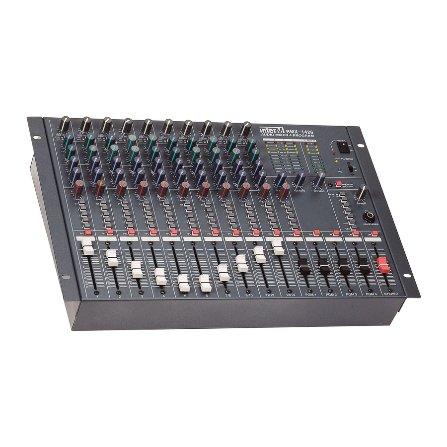
- Page 1 RMX-1426 Multichannel Audio Mixer Copyright 2004 Inter-M Corporation...
-
Page 2: Table Of Contents
Welcome ... 3 Unpacking ...3 Warnings ...3 Operation ...5 Features ... 6 Front Panel Controls... 7 Input Section ...7 Output Section ...10 Rear Panel Controls ... 12 Block Diagram ... 14 Specifications... 15 Contents... -
Page 3: Welcome
A personal welcome to you from the management and employees of Inter-M Thank you for purchasing this fine Inter-M product. All of us here at Inter-M are dedicated to providing you with the highest quality products and the best value. - Page 4 RMX-1426 Multichannel Audio Mixer 8. Do not install near any heat sources such as radiators, heat registers, stoves, or other devices (including amplifiers) that produce heat. 9. Do not defeat the safety purpose of the polarized or grounding type plug. A polarized plug has two blades, with one wider than the other.
-
Page 5: Operation
RMX-1426 Multichannel Audio Mixer Operation Make certain that speakers and input sources are properly connected before switching Keep volume levels at minimum gain before switching on. NOTE: The system’s operation is delayed by approximately three seconds after pressing the AC Mains power switch. This is due to the built-in protection circuitry, designed to... -
Page 6: Features
RMX-1426 Multichannel Audio Mixer Features Multiple Inputs and Outputs • Six mono and four stereo input channels will accommodate a wide array of sound sources including microphones, instruments, cassette and CD players. Four output channels for routing flexibility. Flexible Routing Architecture •... -
Page 7: Front Panel Controls
Front Panel Controls Input Section 1. Peak Indicators These LED indicators light when the input signal to the associated channel is 3dB below clipping. If the indicator is lit steadily, reduce the channel’s Trim level (1) to avoid distortion. 2. Channel Gain Controls These knobs control of gain level for the associated input channel. - Page 8 5. Aux Send Controls These knobs control the Aux Send level for the associated input channel. Rotating the knob clockwise increases the amount of signal sent to the AUX buss. The Aux Send is pre-fader, and is not affected by the channel’s fader position. 6.
- Page 9 RMX-1426 Multichannel Audio Mixer When monitoring the channel’s input signal, PFL position allows you to hear the input at a level unaffected by the position of the channel’s Output, FX Send and Pan settings. AFL position will allow you to hear the input as it appears in the final mix, with Output, FX Send and Pan settings as selected for the channel.
-
Page 10: Output Section
Output Section 1. EFX Return Level This knob controls the EFX Return buss level. The EFX Return is the sum of all signals from the EFX Sends of Channel Inputs (6). 2. EFX Return Balance This knob controls the EFX Return balance, panning the EFX Return buss signal within the stereo buss or PGM 1/2 and PGM 3/4 busses. - Page 11 8. Headphone Output Jack This is a stereo output on balanced 1/4" phone jack, for monitoring the signal of the master output buss. When the PFL switch is activated on an input channel, the signal present at this jack is the input signal of the associated input channel. 9.
-
Page 12: Rear Panel Controls
Rear Panel Controls 1. Mic Inputs 1-14 Mic-level inputs on balanced three-pin XLR connectors. Channels 1-6 are provided at nominal input level of –60dB (mono). Channels 7-10 are provided at nominal input level of –50dB (stereo). 2. Line Inputs 1-14 Line-level inputs. - Page 13 7. Insert I/O These unbalanced 1/4" TRS jacks are provided for input and output of an audio source before the master fader. The Insert signal is unaffected by the Channel Input levels. 8. PGM Outputs 1-4 Line-level outputs on unbalanced 1/4" phone connectors. These are provided for output of signal routed to the PGM output busses.
-
Page 14: Block Diagram
RMX-1426 Multichannel Audio Mixer Block Diagram... -
Page 15: Specifications
Specifications ELECTRICAL Input Sensitivity/Impedance Mic Input 1-6 Mic Input 7-14 Line Input 1-6 Line Inputs 7-14 EFX Returns Sub Inputs (PGM 1-4, Aux, EFX) Output/Impedance Stereo, PGM 1-4 Output AUX, EFX Send Monitor Output Headphone Output Frequency Response ( +1/-2dB) T.H.D (20Hz –... - Page 16 GENERAL Power Source Power Consumption Weight Dimensions Specifications and design subject to change without notice for improvements. 100 –240VAC, 50/60Hz 735 Kg (16.5 lbs) 482(W) x 104(H) x 310(D) mm 19(W) x 4(H) x 12.2(D) in.
- Page 17 Korea and China, and sales and marketing operations located in Japan, Europe, and the U.S.A. With more than 850 employees around the globe, Inter-M is well-poised for further growth and expansion.
Need help?
Do you have a question about the RMX-1426 and is the answer not in the manual?
Questions and answers