Table of Contents
Advertisement
Quick Links
SSC-9700
Instruction Manual
Thank you for purchasing this product.
Please read this manual carefully before using to ensure proper use of this product.
Be sure to read "Safety Precautions" in particular to use the product safely.
Please keep the manual at hand after reading and read it when necessary.
Advertisement
Table of Contents

Subscribe to Our Youtube Channel
Related Manuals for Eizo carina SSC-9700

Summary of Contents for Eizo carina SSC-9700
- Page 1 SSC-9700 Instruction Manual Thank you for purchasing this product. Please read this manual carefully before using to ensure proper use of this product. Be sure to read “Safety Precautions” in particular to use the product safely. Please keep the manual at hand after reading and read it when necessary.
-
Page 2: Table Of Contents
Table of Contents Safety Notice ........................3 Precautions ........................4 Storage and Operating Environment ....................4 Transportation ............................ 5 Maintenance ............................5 Phenomena Specific to CMOS Image Sensors .................. 5 Others ..............................5 Disclaimer ............................6 Contents of This Manual ........................6 Introduction ........................ -
Page 3: Safety Notice
Safety Notice Mount this unit to a stable place with sufficient strength. Tighten all screws and locking mechanism firmly. If the screws are loose, this unit may fall resulting in injury. Falling from height may lead to serious accident. Use at correct power supply and voltage. The rated input voltage of this unit is DC 12 V. -
Page 4: Precautions
Precautions Storage and Operating Environment 0 This unit is intended for indoor use only. Do not use it outdoor. 0 Do not shoot extremely bright subjects (such as lighting and sun) for long periods of time. And avoid placing the product in the following locations. Doing so may result in unwanted operation or malfunction. 0 ... -
Page 5: Transportation
*2 Devices that are involved in one’s safety and have a significant impact on the maintenance of public functions are as follows. 0 Traffic control equipment for aviation, railroads, roads, shipping, etc. 0 Equipment such as nuclear power plants 0 Devices based on the above stated Transportation 0 ... -
Page 6: Disclaimer
Disclaimer 0 We will not be responsible for any inconveniences or disturbances caused in the event of privacy invasion as a result of camera footages of this product. 0 We do not accept liability for the damage of recording or storing image and/or the missing opportunity of recording in the case caused by a problem of this unit. -
Page 7: Introduction
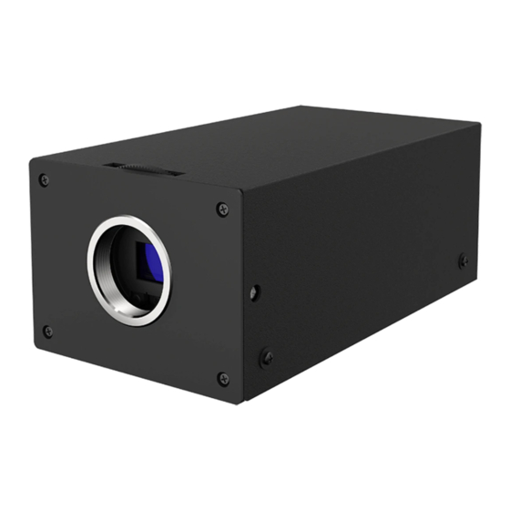
Introduction This unit is an ultra-sensitive single-panel color camera with a 2.12 million pixel 1/1.8-inch CMOS sensor. Ideal for surveillance or security measures and environmental surveys in low light areas at night for borders, harbors and other special purposes. Features 0 ... -
Page 8: Names And Functions Of Parts
Names and Functions of Parts... - Page 9 Name Function Lens Mount (C mount) Mount for installing the lens. Any type of C mount lens can ① be used. When installing the lens, take care to prevent dust or dirt from getting inside. Flange Back Adjuster For adjusting the flange back (distance from the lens ②...
-
Page 10: Operation
Operation User Setup Setup menu can be set on the OSD display. Names and Functions of Setup Buttons Operate using the five push buttons (figure on the right) on the back of the camera. Symbol Name Function Up Button For selecting a setup item (vertical direction) Down Button Left Button For selecting a setup item (horizontal direction) -
Page 11: Alc Menu
ALC Menu ALC Mode Full Auto ・・・・・・・ ALC Level Limits Setup Shutter 1/60 Gain 0.0dB BLC Mode Detailed Settings RETURN EXIT ALC Mode For selecting the method to control the brightness. Full Auto The gain, shutter speed and iris are automatically adjusted. Shut.Prio. - Page 12 BLC Mode The backlight correction can be set using the L and R buttons. Adjusts the best brightness for the entire screen. Automatically corrects the brightness by measuring the light while avoiding extremely bright areas on the entire screen. Spot Automatically selects an area surrounded by a frame on the screen and corrects the brightness so that the other areas are in the best condition.
- Page 13 Remote The Day/Night switching can be operated externally. The B/W Color can be configured by shorting or opening the terminal block 1-2 of the ⑫ RS-485 Day / Night Switch in “Names and Functions of Parts”. The short and open condition changes according to the Main Menu > ALC Detailed Settings > IR Trig Pol.
- Page 14 The difference in operation depending on the lens (DC-Iris lens, fixed Iris lens) when the iris type is set is as follows. OSD Page ALC Detailed Connected Settings Description Operation Lens Configured Iris Detect Value Drives the iris when the Operates as DC-Iris.
-
Page 15: Picture Menu
Picture Menu Picture Auto Knee Auto B.str Black Level ・・・・・・・ Gamma 0.45 High Detail ・・・・・・・ RETURN EXIT Allows you to turn on or off HDR (function that expresses a wide range of brightness by double exposure of low-speed shutter and high-speed shutter). HDR Mode Selecting On allows you to adjust the following items. - Page 16 Black Level The black level of the camera image can be adjusted using the L and R buttons. Gamma Allows you to select the gamma characteristics for the camera according to the display (monitor) used. 0 0.35 to 0.55 (0.01 step)/ 1.0 Even when the background and/or the contour of the subject are among fog, haze, or smoke, as long as they are slightly visible, the function corrects the image by providing contrast so that they become more visible.
-
Page 17: Color Menu
Color Menu Color White Bal. Manual ・・・・・・・ Red Gain Blue Gain ・・・・・・・ Chroma ・・・・・・・ Color Matrix Setup RETURN EXIT White Bal Allows you to switch the white balance mode using the L and R buttons. ATW1 Automatically tracks and adjusts white balance. (Color temperature range: 2500K to 9000K) ATW2 Automatically tracks and adjusts white balance. -
Page 18: Video Output Menu
Video Output Menu Video Output Video Output 1080i/59.94 SDTV Format NTSC-J SDTV Aspect Side Cut SDTV C.Burst Zoom x1.0 Flip/Mirror Normal Video Test Camera RETURN EXIT Video Format Allows you to change the signal format of the HD output. If you change the setting, an “Enter symbol” is displayed. Press the E button to display the confirmation screen. - Page 19 Flip / Mirror Allows you to reverse the image. Normal Normal mode. Flip Flips the image vertically. Mirror Flips the image horizontally. Frip&Mirror Flips the image vertically and horizontally. Video Test Camera Normal state Color Bar Color bar signal Gray Scale Gray scale signal Cross Line Cross line signal...
-
Page 20: Device Setting (1/2) Menu
Device Setting (1/2) Menu Dev. Setting (Page 1/2) Camera ID RS485 ID RS485 Baud. 9600 Setting to Default RETURN EXIT NEXT Camera ID Displays the camera ID when this item is set to On. Pressing the E button to set to On activates the edit mode and the following screen appears. Press the E button at the cursor position (flashing) to perform the following operation. - Page 21 Setting to Default For returning all settings except video out and communication system to factory default. The following items will not return to default setting. 0 Video output mode 0 Camera ID 0 RS-485 ID 0 RS-485 Baud. RS-485, DAY/NIGHT REMOTE Connection Connect according to the diagram below to control via RS-485 or to remotely switch between Day and Night.
-
Page 22: Device Setting (2/2) Menu
Device Setting (2/2) Menu Dev. Setting (Page 2/2) Privacy Mask MenuDispTime 60 Sec Message Disp RETURN EXIT NEXT Privacy Mask Up to 8 different Privacy Masks can be individually set up when this is set to “On”. Selecting Privacy Mask switches the screen to a Privacy Mask display. Privacy Mask Mask1 Mask2... -
Page 23: Information: Version
Information: Version Information Model Name Main Version Firm Version FPGA Version RETURN EXIT Information like Model Name, Serial No, etc. Model Name Model name Main Version Main program version Firm Version Firm program version FPGA Version FPGA program version... -
Page 24: Restrictions On Menu Setting
Restrictions on Menu Setting Some items cannot be set (item not displayed) under certain settings. Refer to here for items that are not displayed. 〇: Can be set, ×: Cannot be set (item not displayed), *: Exception (item is displayed but the setting value is changed because the setting items cannot be used simultaneously) Setting Condition HDR = On... -
Page 25: Menu Structure
Menu Structure TOP Menu ALC Limits Main Menu ALC Limits Setup ALC Mode Full Auto Shutter Limit(H) 1/10000 Picture Setup ALC Level ・・・・・・・ Shutter Limit(L) 1/30 Color Setup Limits Setup Gain Limit(H) 78.0dB Video Output Setup Shutter 1/60 Gain Limit(L) 0.0dB Dev. - Page 26 Video Output Video Output Change Video Output Video Output Change Video Output Video Format 1080i/59.94 SDTV Format NTSC-J SDTV Aspect Side Cut SDTV C.Burst change to 1080p/59.94 Zoom x1.0 CANCEL Flip/Mirror Normal Video Test Camera RETURN EXIT RETURN Device Setting (Page 1/2) Camera ID RS485 Boudrate DEV.
-
Page 27: Specifications
Specifications Camera Unit Image Sensor Single Panel CMOS/ RGB Bayer Array Total Pixels Approximately 2,270,000 pixels 2016 (H) × 1128 (V) Effective Pixels Approximately 2,120,000 pixels 1936 (H) × 1096 (V) Pixel Size 4.1 Μm (H) × 4.1 μm (V) Optical Size 1/1.8 inch Sensor Frame Rate... - Page 28 Interface Image Output Terminal 3G-SDI (BNC) ×1 Composite Video (BNC) ×1 Serial Port RS-485 (Carina original command) Relay Interface IR Cut filter Video Output 3G-SDI 1080P/59.94 (LEVEL A), 1080i/59.94, 1080p/ 29.97, 1080p/50.00 (LEVEL A), 1080i/50.00, 1080p/25.00 Composite Video NTSC, PAL down conversion LETTER BOX / SIDE CUT / SQUEEZE General Power Supply...
-
Page 29: Dimensions
Dimensions 81.4 144.2 1/4-20 UNC 23.5... -
Page 30: Recycling Information
Recycling Information This product, when disposed of, is supposed to be collected and recycled according to your country’s legislation to reduce environmental burden. When you dispose of this product, please contact a distributor or an affiliate in your country. -
Page 31: Warning For Radio Interference
Warning for Radio interference For U.S.A., Canada Only FCC Supplier’s Declaration of Conformity We, the Responsible Party EIZO Inc. 5710 Warland Drive, Cypress, CA 90630 Phone: (562) 431-5011 Trade name: Carina System Co., Ltd. declare that the product Model: SSC-9700 is in conformity with Part 15 of the FCC Rules. - Page 32 For consultation of the product or requests for repair, please contact the dealer / retailer. Issue Date: January 31st, 2022 Carina System Co., Ltd. http://www.carinasystem.co.jp/en EU IMPOTER : Europe GmbH Belgrader Straße 2, 41069 Mönchengladbach, Germany UK IMPORTER : Limited 1 Queens Square, Ascot Business Park, Lyndhurst Road, Ascot, Berkshire, SL5 9FE, UK ©2022 Carina System Co., Ltd.
Need help?
Do you have a question about the carina SSC-9700 and is the answer not in the manual?
Questions and answers