Table of Contents

Subscribe to Our Youtube Channel
Related Manuals for Putzmeister P 718 TD


Summary of Contents for Putzmeister P 718 TD
- Page 1 Operating Instructions Translation of the original Operating Instructions for the machine operator and maintenance personnel to be kept near to the machine at all times Piston pump P 718 TD Machine no. Rev. 08 ---0915 365319013...
- Page 2 Putzmeister Mörtelmaschinen GmbH Max–Eyth–Str. 10 72631 Aichtal Tel. +49 (7127) 599--0 Fax +49 (7127) 599--743 Service--Hotline: +49 (7127) 599--699 Mail: mm@pmw.de Web: www.pmmotar.de...
-
Page 3: Table Of Contents
Contents About these Operating Instructions Foreword ......... . . 1 —... - Page 4 Contents Safety equipment ........2 — 12 Personal protective clothing .
- Page 5 Contents General Technical Description Machine versions ........3 —...
- Page 6 Contents 3.20 Vibrator (option) ........3 —...
- Page 7 Contents 4.11 Electrical connection ....... . 4 — 18 Prerequisites .
- Page 8 Contents Operation Requirements ........6 —...
- Page 9 Contents Catching the wash-out sponge ......6 — 26 High-pressure water cleaning ......6 —...
- Page 10 Contents Maintenance Maintenance and inspection by machine operators ..8 — 2 Maintenance intervals ....... 8 —...
- Page 11 Contents 48- -025 Replacing S-transfer tube ....8 — 102 49- -014 Changing the drawgear ..... . 8 —...
-
Page 13: About These Operating Instructions
E-mail: pmm@pmw.de Service hotline tel.: +49 (7127) 599-699 or the branch or services agent responsible for you. A selection of the Putzmeister Mörtelmaschinen branches and ser- vices agents responsible may be found on the Internet at: www.moertelmaschinen.de The site also contains additional information on operating your ma- chine, including application videos. -
Page 14: Foreword
About these Operating Instructions 1.1 Foreword These operating instructions are designed to familiarise the user with the machine and assist him in using the machine properly in all possible applications. The operating instructions contain important information on how to operate the machine safely, properly and economically. Taking these instructions into consideration will help - - to avoid dangers, - - to reduce repair costs and downtimes,... - Page 15 About these Operating Instructions If after reading these operating instructions you have any questions, please contact your local branch, dealer or the Aichtal Works. You will make it much easier for us to answer any questions if you can give us the details of the machine model and the machine num- ber.
-
Page 16: Signs And Symbols
About these Operating Instructions 1.2 Signs and symbols The following signs and symbols are used in these operating instruc- tions: Action symbol The text following this symbol describes tasks that usually have to be carried out in the sequence shown. ⇒... - Page 17 About these Operating Instructions Danger Important specifications or regulations and prohibitions for preven- ting personal injury or extensive damage appear after the pictogram shown, the word “Danger” written in bold and a line. Accompanying text appears in italics and is underlined. The appropriate symbol will be used if it is possible to identify the source of the danger precisely.
-
Page 19: Safety Regulations
Safety Regulations 2 Safety Regulations This section summarises the most important safety regulations and must be read and understood by all personnel who come into contact with the machine. The various regulations also appear again at the appropriate points in the operating manual. Notes Special safety regulations may be necessary for some tasks. -
Page 20: Terminology
Safety Regulations 2.1 Terminology The following sections explain the terms used in these operating in- structions and describe the requirements for specific groups of per- sonnel. Piston pump The piston pump is a machine for pumping anhydrite and cement liquid screed, fine concrete and mortar grouting as well as concrete spattering. -
Page 21: Workplace
Safety Regulations Workplace The workplace is the area in which people must remain in order to carry out the work. Workplace of the ma- The workplace of the machine operator during operation is at the chine operator operating elements of the machine. Working area The working area is the area in which work is carried out with and at the machine. -
Page 22: Principle
The machine may not be sold on without the accompanying documentation under any circumstances. Reporting an onwards sale or acquisition to Putzmeister ensures that you will be sent any information relating to modifications or in- novations relevant to safety, and you will also be eligible for technical consultancy from our works. -
Page 23: Improper Use And/Or Reasonably Foreseeable Misuse
Safety Regulations 2.3 Improper use and/or Improper use and/or reasonably foreseeable misuse is any use that is not described in the section ”Designated use”, or that goes reasonably foreseea- beyond this. ble misuse The manufacturer shall not be held liable for any consequential da- mage. -
Page 24: Process-Specific Factors
Safety Regulations Process-specific factors Conveyed media The machine is designed exclusively for pumping media as speci- fied in the Technical Data of the machine. The scope of work is limi- ted to operation on construction sites or in workshops. The maximum conveying pressure must not exceed the pressure stated on the rating plate or in the technical data. -
Page 25: Machine-Specific Factors
Safety Regulations Machine-specific factors General servicing and repairs The machine must not be serviced or repaired while it is switched on or unsecured. Ensure that the machine is installed securely, and also that it is secu- red against unauthorised or accidental activation. Other necessary safety measures required on the type of servicing involved;... - Page 26 Safety Regulations Changes to factory set- tings It is prohibited to make any change to the following factory settings: - - Pressure and performance settings - - Software versions and software parameters Structural modifications It is prohibited to fit accessories and attachment parts if they have not been expressly approved by the manufacturer.
-
Page 27: Liability Exclusion
Safety Regulations 2.4 Liability exclusion The manufacturer’s delivery conditions apply. We explicitly draw your attention to the fact that the manufacturer shall not be held liable for damage in the cases listed therein. The manufacturer shall not be liable for damage caused by: - - improper use and/or reasonably foreseeable misuse - - improper operation, maintenance, servicing or repairs. -
Page 28: Personnel Selection And Qualifications
Safety Regulations 2.5 Personnel selection The machine may only be operated or serviced independently by persons who and qualifications - - have reached the minimum legal age; - - are physically capable (rested and not under the influence of alco- hol, drugs or medication);... -
Page 29: Sources Of Danger
Safety Regulations 2.6 Sources of danger Never reach into the moving parts of the machine, whether the ma- chine is running or switched off. Always switch off the main switch first. Take note of the warning plate. In the event of malfunctions, stop the machine immediately and se- cure it. -
Page 30: Safety Equipment
Safety Regulations 2.7 Safety equipment Never remove or modify safety devices on the machine. Any safety devices removed for set- -up, maintenance or repair pur- poses must be refitted and checked immediately upon completion of the maintenance and repair work. All equipment required for safety and accident prevention (warning signs and information plates, cover grilles, guards, etc.) must be in place. -
Page 31: Personal Protective Clothing
Safety Regulations 2.8 Personal protective To reduce the risk to life and limb, the following personal protective clothing must be worn whenever necessary or required by regula- clothing tions. Protective helmet, protective gloves and safety boots are always specified for all persons working at or with the machine. Personal protective clothing must at least comply with the specified standards. - Page 32 Safety Regulations Protective goggles Protective goggles protect your eyes against injuries from concrete spatters or other particles. (EN ISO 166; Personal eye protection - - Specifications) Safety harness A safety harness protects you against falling when you are working on scaffolding, bridges or in similar areas. (EN ISO 361;...
- Page 33 Safety Regulations Different models available Item Designation Protective helmet Ear defenders Protective goggles Face protection visor Protective suit Protective gloves Protective boots Danger The machine operator must be informed that waterproof protective clothing only provides protection from spray water and splash parti- cles.
-
Page 34: Risk Of Injury - - Residual Risk
Safety Regulations Risk of injury - - resi- The machine has been built in accordance with state of the art tech- nology and meets all the relevant safety requirements. Nevertheless, dual risk its use may constitute a residual risk to life and limb of the operator or of third parties, or cause damage to the machine and to other pro- perty. -
Page 35: Danger Of Crushing And Bumping
Safety Regulations 2.10 Danger of crushing During the following operating modes at the machine: - - Set-up and bumping - - Starting up - - Operation - - Cleaning, Troubleshooting, Maintenance - - Decommissioning Danger of crushing and bumping. Transporting the ma- When loading the machine with a crane onto a transport vehicle, chine the machine must only be suspended on the attachment points pro-... - Page 36 Safety Regulations Suspended Load Hoisted loads may fall if they are not loaded properly or if the auxi- liary loading equipment is damaged. Make sure personnel do not walk under suspended loads. Only use an auxiliary loading device with a load bearing capacity designed to support the gross weight of the machine! Danger If a central jack ring is fitted (option), the crane can only lift the ma-...
-
Page 37: High-Pressure Injection
Safety Regulations 2.11 High-pressure injec- The high-pressure water pump, high-pressure hose and high-pres- sure gun pose a risk of high-pressure injection during the following: tion - - Starting up - - Operation - - Cleaning, Troubleshooting, Maintenance - - Decommissioning the discharge connection, the delivery line and at the spray gun will present a hazard from high pressure injection. -
Page 38: High-Pressure Hoses
Safety Regulations High-pressure hoses It is essential that correct high-pressure hoses be carefully selected and handled correctly to maintain the operational safety of the ma- chine. Observe the following rules when handling high-pressure hoses: - - Only use high-pressure hoses approved to withstand the maxi- mum operating overpressure and maximum operating tempera- ture. -
Page 39: High-Pressure Gun
Safety Regulations Danger Never search for leaks in high-pressure hoses with your bare hands. An escaping high-pressure jet may not be visible and can cause se- rious injury. High-pressure gun Correct handling of the high-pressure gun is essential for the opera- tional safety of high-pressure cleaners. -
Page 40: Electrical Contact
Safety Regulations 2.12 Electrical contact The control cabinet, electrical wiring and drive motor pose a risk of fatal injury from electrical contact during the following: - - Setting up - - Operation - - Cleaning, Troubleshooting, Maintenance - - Decommissioning All electrical assemblies are protected as standard, as per IEC 60204 Part1 or DIN 40050 IEC 144 in accordance with protec- tion category IP 54. -
Page 41: Blockage
Safety Regulations 2.13 Blockage Avoid blockages. A well cleaned and leak-tight delivery line is the best assurance against formation of a blockage! Blockages conside- rably increase the risk of accident. Danger Never attempt to blow out a blockage with compressed air. There is a risk of fatal injury because the delivery line can burst! Injury through the force of bursting couplings, pipelines or blockages flying out of delivery lines, end hose and pump hopper. -
Page 42: Hydraulic And Pneumatic Equipment
Safety Regulations 2.14 Hydraulic and pneu- Work on hydraulic equipment may be carried out only by persons having special knowledge and experience in hydraulic systems, who matic equipment can demonstrate to us appropriate certification of competence (certi- ficates of training). Wear a face mask and gloves whenever you work on the hydraulic system. -
Page 43: Dumping Pressure
Safety Regulations Do not repair damaged hydraulic lines, but replace them. Replace damaged or saturated hydraulic hoses immediately. Even if no external damage is detected, hydraulic hoses must be re- placed every six years (including a storage time of no more than two years). -
Page 44: Place Of Work
Safety Regulations 2.15 Place of work The place of work is the area in which people must remain in order to carry out the work. Machine operator The place of work of the machine operator during operation is at the operating panel on the machine. -
Page 45: Sound Emissions
Safety Regulations 2.18 Sound emissions During the following operation modes: - - Starting up - - Operation - - Cleaning, Troubleshooting, Maintenance - - Decommissioning Sound emissions. Refer to the technical data for the sound power level value in the vici- nity of the machine. -
Page 46: Safety-Related Parts (Srp)
Safety-related parts (SRP) much only be maintained, repaired and replaced by authorised Putzmeister specialists. If a safety-related part (SRP) is incorrectly maintained, repaired or replaced, this can result in safety functions not operating correctly. -
Page 47: Spare Parts
Spare parts must comply with the technical requirements specified by the manufacturer. Spare parts from original equipment manufac- turers guarantee this. Use only original spare parts. Putzmeister Mörtelmaschinen GmbH accepts no liability for damage caused as a result of using non-origi- nal spare parts. -
Page 48: Accessories
Notes Accessories that are not included in the scope of supply delivered with the machine are supplied by Putzmeister and can be purchased through Parts Sales. Please refer to the delivery note for a list of accessories supplied. -
Page 49: Injuries Through Unauthorised Starting Or Use Of The Machine
Safety Regulations 2.23 Injuries through unau- During the following operating modes at the machine: - - Starting up thorised starting or - - Operation use of the machine - - Cleaning, Troubleshooting, Maintenance - - Decommissioning there is a risk due to unauthorised starting or use of the machine. Always secure the machine against unauthorised starting before lea- ving the work area. -
Page 51: General Technical Description
The following data can be found on the rating plate: - - Machine model - - Machine number Notes The machine number is allocated by Putzmeister Mörtelmaschinen GmbH. Each machine number is only allocated once. This means that the machine number identifies each individual machine. 3 — 1... -
Page 52: Machine Designation
P 718 series Available machine models and versions from the P 718 series. Machine model Versions P 718 TD Trailer machine with diesel engine P 718 TE Trailer machine with electric drive motor P 718 SD... - Page 53 General Technical Description 3.5 Summary Below you will find a summary of the most important components, which are described on the following pages. The description includes the available machine models and the va- rious versions with a diesel engine or electric motor. Stationary machine Illustration shows diesel version Item...
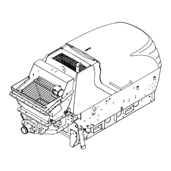
- Page 54 General Technical Description Mobile machine Illustration shows diesel version Item Designation Hopper Protective grille Control cabinet Engine Hydraulic fluid reservoir Trailer coupling ring Support wheel Fuel tank filler neck Support leg with support foot Agitator cut-out (partially obscured) Lighting equipment Pressure connection 3 —...
-
Page 55: Technical Data
General Technical Description 3.6 Technical data The following technical specifications and attributes relate to the P 718. P 718 TD P 718 TE P 718 SD P 718 SE Dimensions Length: 4503 mm 3025 mm Width: 1600 mm 1270 mm... - Page 56 General Technical Description P 718 TD P 718 TE P 718 SD P 718 SE Performance data 3-cylinder 3-cylinder electric motor electric motor diesel engine diesel engine Engine: 30 kW 400 V, 30 kW 400 V, 34.5 kW at 34.5 kW at...
- Page 57 General Technical Description P 718 TD P 718 TE P 718 SD P 718 SE Tyres Tyre size: 225/75 R16C 6J 121 N Rim size: 6J x 16 H2 Inflation pressure: 5.25 bar Tightening torque of Flanged nuts 210 Nm...
-
Page 58: Rating Plate
General Technical Description 3.7 Rating plate The most important machine data is shown on the rating plate. Item Designation Model (machine model) Year of manufacture Maximum delivery pressure [bar] Hydraulic pressure [bar] (maximum fluid pressure in the hydraulic system) Voltage [V] Frequency [Hz] Power [kW] Licence number... -
Page 59: Sound Power Level
General Technical Description 3.8 Sound power level In accordance with Directive 2000/14/EC the sound power level emit- ted by the machine is given below. Next to the rating plate on the machine there is the plate shown in the picture below which gives the machine’s sound power level mea- surement. -
Page 60: Options
General Technical Description 3.9 Options Consult your dealer or local Putzmeister Mörtelmaschinen GmbH re- presentative as to how and whether you should upgrade your ma- chine. Notes Please refer to the current catalogue from Putzmeister Mörtelmaschinen GmbH for information on other options and acces- sories. -
Page 61: Safety Equipment
Personal protective Personal protective equipment is not included in the products sup- equipment plied with the machine. However, it is supplied by Putzmeister Mör- telmaschinen GmbH and can be purchased via the Parts Sales de- partment. Danger Wear all necessary personal protective equipment. This also applies to all personnel standing within the working area around the machine (for their own safety). -
Page 62: Agitator Cut-Out
General Technical Description Pressing the EMERGENCY STOP button triggers the following func- tions: - - The pump stops. - - The agitator stops. Notes To cancel the EMERGENCY STOP status, unlock the depressed EMERGENCY STOP button by turning it. Emergency manual operation of the pump is possible by manually operating the switch-on valve and switchover valve at the fully hy- draulic control block. -
Page 63: Control Cabinet
General Technical Description 3.11 Control cabinet The machine is operated and controlled from the control cabinet. Heavy current Work on the electrical system and equipment of the machine should be carried out by a qualified electrician or by instructed persons un- der the supervision and guidance of a qualified electrician in accor- dance with the electrical engineering rules and regulations. - Page 64 General Technical Description Operating / control Item Function / display elements Pressure gauge Hydraulic fluid pressure Indicator lamp Lack of oil Operating hours Analogue readout of elapsed meter pump time Indicator lamp Fault Indicator lamp Central lubrication system (optional) Flip switch Vibrator ON (optional) Toggle switch...
-
Page 65: Operating Elements
General Technical Description 3.12 Operating elements Further elements have been installed on the machine for operation and control. Different models available Item Designation Control cabinet (under flap) Manual throttle lever Bracket for cable remote control (depending on model) Delivery rate controller Mixer lever “Agitator PUMPING - 0 - MIXING”... -
Page 66: Core Pump
General Technical Description 3.13 Core pump Putzmeister pumps are driven by the drive motor hydraulically via oil pumps. Item Designation Piston rod Water box Delivery piston Delivery cylinder S-transfer tube Pressure connection Delivery line The delivery pistons(3) are connected via intermediate flanges to the piston rods(1) of the drive cylinder. -
Page 67: Water Box
General Technical Description Water box The water box(2) is fitted between the drive and delivery cylinders. The water in the water box has the following functions: - - It cools the delivery pistons and the piston rods. - - The water rinses the inner wall of the delivery cylinders. Pumping The returning delivery piston sucks the medium in from the hopper. -
Page 68: Mixer
General Technical Description 3.14 Mixer The hopper is equipped with a hydraulically driven mixer. The mixer has two functions: - - It improves the fill level of the delivery cylinder. - - It mixes the medium. Item Designation Hydraulic motor Mixer shaft Mixer paddles During pumping, the fill level in the delivery cylinders should be as... -
Page 69: Engine / Drive Motor
General Technical Description 3.15 Engine / drive motor The machines are powered by a 3-cylinder diesel engine or an elec- tric motor. Diesel engine Different models available Item Designation Drive motor Oil filler Oil dipstick Fuel filter Engine oil filter Oil drain plug Dry air filter 3 —... -
Page 70: Hydraulic Pump
General Technical Description Electric motor Different models available Item Designation Electric motor Hydraulic pump The drive motor (1) has different performance values, depending on the model. Refer to the rating plate or the chapter “General technical descrip- tion”, section: “Technical data” for drive motor values. Notes For further information on the drive motor, refer also to the documen- tation of the motor manufacturer. - Page 71 General Technical Description 3.16 Hydraulic pump The hydraulic pump flanged onto the drive motor. Item Designation Main pump Switch cylinder auxiliary pump Agitator auxiliary pump The hydraulic pump consists of the main and auxiliary pumps. - - The main pump(1) creates the oil flow in the closed oil circuit, which drives the drive cylinders of the machine.
-
Page 72: Pressure Calibrator
General Technical Description 3.17 A pressure calibrator is integrated in the machine. Pressure calibrator The calibrator is used to adjust the delivery pressure to a setting bet- ween 40 and 70 bar. A padlock is attached for security. The pressure calibrator is located at the front left of the frame, vie- wed in the direction of travel. -
Page 73: Cable Remote Control (Optional)
General Technical Description 3.18 Cable remote control A cable remote control is available as an option. Pump functions and the EMERGENCY STOP can be activated using (optional) the cable remote control. Pos. Designation Cable remote control Interface cable Connector The socket for the interface cable is located under the control cabi- net. -
Page 74: Radio Remote Control (Option)
General Technical Description 3.19 Radio remote control A radio remote control system is available as an option. The radio remote control is used to activate the pump functions and (option) the EMERGENCY STOP. Item Designation Receiver (integrated in side of frame) Antenna Charger (in toolbox) Transmitter (in toolbox) - Page 75 General Technical Description Transmitter Operating / control Item Function / display elements Emergency stop button for swit- Button ching off the machine in an emer- gency Indicator lamp Status LED Button Start Pump ON - - 0 - - Reverse pumping Flip switch Electronic key Contains all the data required for...
-
Page 76: Vibrator (Option)
General Technical Description 3.20 Vibrator (option) The machine can be fitted with a vibrator as an option. Item Designation Vibrator Vibrator cable Grille The vibrator mounted on the grille is connected to the socket provi- ded on the machine. The vibrator is switched on and off via the ”Vibrator on” toggle switch. -
Page 77: High-Pressure Cleaner (Option)
General Technical Description 3.21 High-pressure cleaner A hydraulically driven high-pressure cleaner can be installed as an option. (option) The high-pressure cleaner is used to clean the outside of the ma- chine with pressurised water. Caution The high-pressure cleaner must never be operated without water. Make sure that the water inlet is connected correctly. - Page 78 General Technical Description Wear all the necessary personal protective equipment during opera- tion. Refer also to chapter: ”Safety regulations” - - section: ”Protective equipment”. Danger Waterproof protective equipment only provides protection from spray water and splash particles. In the case of direct contact with the high-pressure water jet, protective clothing does not provide suffi- cient protection from injury.
-
Page 79: Flushing Water Pump (Option)
General Technical Description 3.22 Flushing water pump A hydraulically driven flushing water pump can be installed as an option. (option) The flushing water pump is used to wash the outside of the machine with pressurised water. The flushing water pump is on the right side of the engine compart- ment in direction of travel. - Page 80 General Technical Description Different models available Item Designation Pressurised water hose connection Flushing water pump pressure gauge Switching valve At the switching valve in the engine compartment, you can select between operation of the flushing water pump or the agitator. To switch on the flushing water pump, set the switching valve to the ”Flushing water pump”...
-
Page 81: Centralised Lubrication System (Option)
General Technical Description 3.23 Centralised lubrica- A centralised lubrication system can be installed as an option. tion system (option) Different models available Item Designation Grease distributor Pressure limiting valve Filling nipple Centralised lubrication pump element Plug connector The electrically driven centralised lubrication pump conveys lubri- cant from the grease distributor to the connected lubrication points during the lubrication period. -
Page 82: With Controller Card
General Technical Description Technical data: Electrically operated centralised lubrication pump: Capacity: Output flow rate: 4 cm /min Lubrication point pressure: max. 100 bar Control voltage: 12 V Service temperature: - -25 °C to +70 °C Lubricant: Multipurpose grease NLGI Class 2 Mineral oil with min. - Page 83 General Technical Description A function check of the centralised lubrication system is performed every time the machine is switched on. The indicator lamp lights up for 2 seconds during the function check. The indicator lamp(2) indicates the operating status of the centrali- sed lubrication system.
-
Page 85: Transport, Set-Up And Connection
Star- ting up the machine will not be described until the chapter ”Starting up”. Putzmeister trailer machines may only use public roads if properly 4.1 Transport and driving approved. They are subject to Road Traffic laws when being towed in road traffic. -
Page 86: Transporting The Machine
Transport, Set-up and Connection 4.2 Transporting the ma- If you wish to load the machine onto a suitable transport vehicle, jack rings must be fitted on the machine. chine Use the slinging points provided on the machine when loading it by crane. -
Page 87: Transporting Stationary Machines
Transport, Set-up and Connection 4.3 Transporting statio- The machine has no attachment points and should therefore be loa- ded onto a suitable transport aid. Use a suitable fork-lift truck to lift nary machines the machine. The machine is fitted with runners with integral slots for accommoda- ting the fork on a fork-lift truck. -
Page 88: Before A Journey
Transport, Set-up and Connection 4.4 Before a journey Observe the following points before moving the machine on the open road using a towing vehicle: - - The machine is now shut down correctly. Refer also to chapter: “Shutting down”. - - The machine is in transport position. - - The machine is correctly coupled. -
Page 89: Transport Position
Transport, Set-up and Connection Transport position Before transportation, the machine must be placed in transport posi- tion: - - The lighting equipment is installed on the machine and connected. - - The hood is closed tightly. - - The hopper is empty. - - The hopper grill is closed. -
Page 90: Lighting Equipment
Transport, Set-up and Connection Lighting equipment The machine is fitted with lighting equipment. Notes The lighting equipment is designed to run off 12 V as standard. Use a suitable adapter for the 24V voltage option Different models available Item Designation Lighting equipment Power cable Connector... -
Page 91: Towing Gear
Transport, Set-up and Connection 4.5 Towing gear The towing vehicle must be equipped with a trailer coupling desi- gned to withstand the relevant trailer and drawbar loads. Ground clearance The machine must have the maximum possible ground clearance while it is being towed. It must be ensured that the machine is hori- zontal when it is attached ready for towing. -
Page 92: Adjusting The Towing Gear
Transport, Set-up and Connection Adjusting the towing To adjust the towing gear, proceed as follows: gear Different models available Item Designation Towing gear Locking toggle Spring pin Lever (pipe) Pull the spring pin(3) from the locking toggle(2). Release the locking toggle and turn it as far as the stop. ⇒... -
Page 93: Parking Brake
Transport, Set-up and Connection 4.6 Parking brake A parking brake is fitted to secure the machine when parked. The axle and wheels are fitted with a gas-filled spring, depending on the version. The gas-filled spring assists the braking force. When the automatic reversing device engages (the machine rolls backwards), the gas-filled spring automatically clamps the wheel brake. -
Page 94: Brake Safety Cable
Transport, Set-up and Connection Brake safety cable The brake safety cable connects the trigger mechanism on the lok- king brake lever with the towing vehicle and acts as the trailer’s emergency brake, should it become disconnected from the towing vehicle for whatever reason. The brake safety cable is designed such that it cannot pull the trailer when the trailer coupling has been released. - Page 95 Transport, Set-up and Connection 4.7 Ball hitch The ball hitch is equipped with a safety control display. This consists of clearly imprinted symbols, which are pasted over with a red- green-red label with the same symbols, and a pointer. Item Designation Ball hitch Hitch handle...
- Page 96 Transport, Set-up and Connection Caution Do not put your hands inside the coupling when it is open! Even low pressure on the spherical cap can activate the spring-loa- ded closing mechanism and cause an injury. After correct engagement of the ball hitch, the pointer jumps to the green area of the marking, which is identified by a ”+”...
-
Page 97: Permitted Slewing Circle Of The Ball Hitch
Transport, Set-up and Connection Danger If the indicator is in the red ”- ” area, then the ball hitch is not connec- ted properly and the trailer must not be driven under any circumstan- ces. The ball hitch can slip out - risk of accidents! Have worn parts repla- ced immediately. -
Page 98: Coupling The Ball Hitch
Transport, Set-up and Connection Coupling the ball hitch To couple the trailer, proceed as follows: Drive the towing vehicle backwards close to the hitch handle on the trailer. Danger of crushing For safety reasons, make sure that nobody is standing between the towing vehicle and the trailer. - Page 99 Transport, Set-up and Connection Notes If the drawbar load is heavier, a support wheel can be used to raise and lower the trailer depending on the version. For safety reasons, press the hitch handle all the way down by hand. The coupling mechanism is correctly locked when the hitch handle can no longer be pressed down(C).
-
Page 100: Disconnecting Ball Hitch
Transport, Set-up and Connection Raise the existing support or support wheel to the top position. Notes Always raise and secure the support / support wheel completely be- fore transporting. Disconnecting ball hitch To disconnect the trailer, proceed as follows. Secure the machine using the chocks. Support the machine using the existing support or support wheel. -
Page 101: Selecting The Set-Up Site
Transport, Set-up and Connection 4.8 Selecting the set-up The set-up site of the machine is usually determined and appropria- tely prepared by the site management. site Notes The responsibility for setting up the machine safely falls on the ope- rator. 4.9 Set-up site require- Inspect the proposed site carefully and reject the set-up site if you have any doubts in respect of safety. -
Page 102: Setting Up
Transport, Set-up and Connection 4.10 Setting up The machine must be set up so that it is absolutely stable and secu- red against rolling. Secure the machine against rolling by placing chocks under the wheels. Apply the handbrake on machines with brake equipment. Align the machine horizontally. -
Page 103: Aligning The Machine
Transport, Set-up and Connection Aligning the machine Align the machine horizontally. Different models available Item Designation Support foot Connecting bolt Spring pin Wind the support wheel up or down using the crank handle un- til the machine is horizontal. Pull out the spring pin(3). Hold the support leg(1) firmly in position while pulling out the locking pin(2). -
Page 104: Electrical Connection
Transport, Set-up and Connection 4.11 Electrical connection Please also refer to the ”General Technical Description” or the electri- cal circuit diagram for the electrical connection values. Refer also to chapter: ”General Technical Description” - - section: ”Technical data” and “rating plate” for more details. Heavy current Work on the electrical system and equipment of the machine must be carried out by a qualified electrician or by instructed persons un-... -
Page 105: Laying Electrical Supply Cables
Transport, Set-up and Connection Laying electrical supply Supply cables must be laid visibly, taking local conditions into consi- cables deration, and secured against damage. Danger There is a danger of electric shock which may have lethal conse- quences by: – contact with electrical cables; –... -
Page 107: Starting Up
Starting up 5 Starting up In this chapter you will find information on starting up the machine. The work steps for initial operation of the machine are described as well as how to prepare the machine for operation after a long break. There is also a description on how to check the condition of your ma- chine and how to carry out a test run with function checks. -
Page 108: Checks
Starting up 5.1 Checks Each time the machine is used, you should check the condition of your machine and carry out a test run including function checks. If you identify any defects during the checks, you must eliminate these (or have these eliminated) immediately. Visual checks Some important visual checks should be carried out before starting up the machine. -
Page 109: Operating Materials
Caution Putzmeister accepts no liability for damage resulting from the use of unauthorised operating materials. The documentation provided by the manufacturer is always decisive. Use only the lubricants specified in the lubricant recommendation. -
Page 110: Fuel Level
Starting up Check all water, oil and fuel levels and top these up as neces- sary. Caution After checking and topping up (if necessary), all filler lids must again be sealed tightly. Fuel level The fuel level must be as close as possible to the “Max” marking. Check the fuel level at the fuel tank. -
Page 111: Checking The Dry Air Filter
Maintenance chart: Checking and replacing hydraulic hose lines Caution Operation is not possible if the hydraulic cylinders are not tight. Consult a service engineer from Putzmeister Mörtelmaschinen GmbH, or a dealer authorised by Putzmeister Mörtelmaschinen GmbH. 5 — 5 09_0126_0709GB... -
Page 112: Hydraulic Oil Level
Starting up Hydraulic oil level You can check the hydraulic oil level at the fill level indicator for the hydraulic fluid reservoir. Check the hydraulic oil level at the fill level indicator for the hy- draulic fluid reservoir. Top up the hydraulic oil if necessary. Notes Only fill the hydraulic fluid reservoir through the mesh in the filler pipe. -
Page 113: Checking The Water Box
Starting up Checking the water box The following must be checked in the water box: - - Water level: The piston rods must be completely covered. - - Water condition: The drive cylinders are leaking if there is a clearly visible escape of oil, particularly at the piston rods. -
Page 114: Checking Parts That Come Into Contact With Medium
Starting up Checking parts that Before use, you should always check the condition of parts that come into contact with come into contact with the medium: medium From the pressure connection end, shine a light down the transfer tube using a flashlight and check the inner wall of the tube and the thrust ring for wear. -
Page 115: Refuelling The Machine
Starting up 5.2 Refuelling the ma- Before starting up, check that there is sufficient fuel in the tank and top up the fuel via the filler neck if necessary. Shut down the machine chine and then refuel it via the filler neck. Notes Always fill the tank well in advance, as it will otherwise be necessary to vent the fuel line to the diesel engine. -
Page 116: Test Run
Starting up 5.3 Test run For the test run, first start the drive motor and then switch on the pump. Some functions must be checked while the machine is run- ning. Notes Any defects found during these tests must be rectified immediately. A fresh inspection is necessary after every repair. - Page 117 Starting up Different models available Item Designation Control cabinet (under flap) Manual throttle lever Delivery rate controller Mixer lever “Agitator PUMPING - 0 - MIXING” Set the delivery rate controller to “min”. Set the “Agitator PUMPING - 0 - MIXING” mixer lever to neutral position.
- Page 118 Starting up Different models available Item Designation Toggle switch “Pump ON - 0 - Reverse pumping ON” Toggle switch “Local - 0 - Remote” Toggle switch “Acknowledge EMERGENCY STOP” Ignition start switch “Drive motor ON” Notes The control cabinet is fitted with an optical hazard warning device, i.
- Page 119 Starting up Actuate the “Acknowledge EMERGENCY STOP” toggle switch. ⇒ The machine is ready for service. Manual throttle to slightly above idling Set the manual throttle to slightly above the “min” mark. Caution Always set the motor to above the speed where it begins to shake (500- 700 rpm).
-
Page 120: Switching On Pump
Starting up Switching on pump The machine is ready for service and the pump can be switched on once the warming-up phase has ended. Manual throttle to slightly above idling Set the manual throttle to slightly above the “min” mark. Caution Always set the motor to above the speed where it begins to shake (500- 700 rpm). -
Page 121: Switching On The Agitator
Starting up Switching on the agita- The agitator must be switched on for pumping or mixing. Different models available Item Designation Mixer lever “Agitator PUMPING - 0 - MIXING” Set the “Agitator PUMPING - 0 - MIXING” mixer lever to “PUM- PING”. -
Page 122: Function Checks
Starting up 5.4 Function checks Before using the machine, the following functions should be checked with the machine running. Notes You must close the hood after carrying out the check and test opera- tions. When closing the hood, the hood interlock must audibly en- gage. -
Page 123: Hydraulic Filter
Starting up Hydraulic filter Contaminated hydraulic filters considerably reduce the oil flow rate and may damage the hydraulic system. Check the reverse fine filter as follows: Let the pump run to warm up until the hydraulic oil has reached service temperature. (>50 C). Set the output controller to the maximum output. - Page 124 Starting up Notes When switching on the machine, the red button on the contamination indicator can pop out if the drive motor is cold. Press the button back in only when service temperature has been reached. If necessary, press the red button of the contamination indica- tor back in.
-
Page 125: Function Check For The Emergency Stop Button
Starting up Function check for the Inspect the EMERGENCY STOP button to ensure that it is functioning EMERGENCY STOP but- properly. Danger Operating personnel must inspect the EMERGENCY STOP button daily to ensure that it is functioning properly. Caution Only press the EMERGENCY STOP button in the event of danger. Do not use the EMERGENCY STOP button to switch off the machine. - Page 126 Starting up Unlock the EMERGENCY STOP button by turning it. Press the “Acknowledge EMERGENCY STOP” toggle switch. ⇒ The EMERGENCY STOP is acknowledged. ⇒ The “Fault” indicator lamp goes out. Caution The machine is no longer safe to operate if the EMERGENCY STOP button is defective, as you will no longer be able to switch off the ma- chine quickly enough in the event of potential danger.
-
Page 127: Function Check Of The Agitator Cut-Out
Starting up Function check of the The machine is equipped with an agitator cut-out. The agitator cut- agitator cut-out out switches off the agitator if the agitator grill or hopper attachment is opened during operation. Check that the agitator cut-out is fully functional. Start the drive motor. - Page 128 Starting up Different models available Item Designation Hopper attachment Limit switch Notes The safety device at the hopper attachment(1) is equipped with a limit switch(2) which switches off the agitator as soon as the hopper attachment is raised. Raise the hopper attachment(1). ⇒...
-
Page 129: The Delivery Line
Starting up 5.5 The delivery line Only use original Putzmeister delivery lines which meet prescribed operating and burst pressures. Notes Only Putzmeister couplings and fittings are guaranteed to comply with the values specified in the German Accident Prevention Regula- tions. -
Page 130: Shutting Down Machine After Initial Operation
Starting up 5.6 Shutting down ma- After the function check, you can shut down the machine. chine after initial ope- ration Item Designation Toggle switch ”Pump ON - - 0 - - Reverse pumping ON” Output controller Control reduction of the output controller(2). ⇒... - Page 131 - - the delivery line has been laid professionally. Notes Should a malfunction occur when the pump is in operation, first con- sult the chapter ”Faults, Cause and Remedy”. Contact Putzmeister’s After Sales department for advice, if you are unable to rectify the fault yourself.
- Page 132 Operation 6.2 Emergency shutdown Make sure you are completely familiar with the procedures for shut- ting down the machine in an emergency situation before you start procedures operating the machine. Danger Proceed immediately as described below if an emergency occurs while you are operating the machine.
- Page 133 Operation Press the EMERGENCY STOP button. ⇒ The pump must come to a halt immediately. ⇒ The agitator stops. ⇒ The drive motor moves to idle speed. ⇒ The “Fault” indicator lamp lights up. Take emergency measures, where necessary. Note the incident and report in accordance with company pro- cedures.
-
Page 134: Concrete Properties
Operation 6.3 Concrete properties The concrete properties such as consistency and grading curve are decisive factors for an optimised fill level of the delivery cylinders. The fill level, in turn, has a decisive influence on the efficiency of the pump, i.e. the concrete delivery rate per stroke. Saturated mixture Item Designation... -
Page 135: Filling Agitator Hopper
Operation 6.4 Filling agitator hopper Always fill the agitator hopper with medium up to the mixer shaft. Danger Entrapped air in the delivery line is dangerous since the compressed air is expelled suddenly from the end of the delivery line and the me- dium can be ejected explosively. -
Page 136: Initial Pumping
Operation 6.5 Initial pumping The procedure for beginning forward pumping up to the point in time at which a continuously flowing jet emerges from the delivery pipe is designated as ’initial pumping’. This can take place at the start of building site operations, but also after pumping interruptions. -
Page 137: Pumping
Operation 6.6 Pumping Correct mixing of the concrete influences pumping performance. Mix the concrete vigourously in the truck mixer at maximum speed. Ensure that the concrete mix is uniformly prepared. If concrete additives are required (liquefier, set retarding ad- mixture), continue mixing after their addition for at least 4 minu- tes. -
Page 138: Monitoring
Operation 6.7 Monitoring During pumping operations, the displays on the monitoring instru- ments must be observed. Check all displays of the monitoring instruments: Hydraulic pressure gauge: the value indicated on the pressure gauge must not exceed the maximum value specified on the rating plate. -
Page 139: Blockages
Operation 6.8 Blockages Item Designation Jammed aggregate Cement paste Boundary layer The following defects can lead to blockages: - - The delivery pipe is insufficiently wetted. - - Transfer tube is leaking. - - The pipes are not seal-tight. - - Residual concrete in transfer tube and delivery line. - - Unfavourable concrete composition. -
Page 140: Breaks In Pumping
Operation 6.9 Breaks in pumping You should avoid breaks in pumping as far as possible, as the con- crete in the delivery line can start to set, or can become segregated due the vibrations of the machine. Note the following points if breaks are unavoidable: - - Never leave the delivery pipe under pressure. -
Page 141: Drive Motor
Operation 6.10 Drive motor Never exceed the permissible engine speed specified on the rating plate of the machine. Always set the engine speed higher than the vibrating speed. Do not shut the drive down immediately following periods of high engine load, but first allow it to cool down by idling under no load. -
Page 142: Cooling Unit
Operation Cooling unit Change the water continuously if the temperature continues to rise. Search for the cause of the fluid overheating and correct it if the safety regulations permit this during pumping operations. Additional cooling If these measures are insufficient, in case of emergency you can cool the drive cylinder with a water jet. -
Page 143: Restarting
Operation Restarting However, if the pump cuts out because of overheating, you should proceed as follows: Switch the pump off. Notes Do not shut down the motor, as the hydraulic fluid radiator must re- main in operation. Refresh the water in the water box. Wait until the hydraulic fluid has cooled if you are not able to find the fault immediately. -
Page 144: Cleaning
Operation 6.12 Cleaning Concrete residue that has settled on the inside of the delivery line or transfer tube can cause damage, can build up further and further and thus narrow the cross-section. A clean delivery pipe and transfer tube are therefore indispensable to be able to begin fault-free deli- very when they are next used. - Page 145 Operation No water into electric systems Environmental protection During all cleaning work, observe the waste disposal regulations that apply to your region. Cleaning additives or diesel fuel must not be permitted to enter the sewage system. Water which sprays the machine from all directions does not have any damaging effect.
-
Page 146: Residual Concrete
When cleaning with compressed air there is an increased danger of accidents. Cleaning may only be performed by a proficient person or under the supervision of such a person. Putzmeister accepts no lia- bility for any damage that is caused by the improper implementation of compressed-air cleaning. -
Page 147: Cleaning Preparations
Operation Cleaning preparations In order to be able to clean the delivery line and the machine imme- diately after use, we recommend that you make the following pre- parations at an early stage, depending on the cleaning process. For proper cleaning you need a sufficient quantity of sponge balls and other cleaning accessories. - Page 148 Operation Item Designation Coupling Catch basket (closed pipe segment) Spring pin (on two sides) Catch bracket Continuation next side 6 — 18 05_0010_0507GB...
-
Page 149: Wash-Out Adapter
Operation Wash-out adapter The wash-out adapter is used for cleaning with pressurised water or compressed air. Danger The wash-out adapter is not allowed to be installed on the delivery line during pumping operation, as the flushing connections and shut- off cocks are not designed for the pump pressure. It must only be used for cleaning with pressurised water or compressed air up to 10 bar. -
Page 150: T-Delivery Pipe With Cleaning Port
Operation T-delivery pipe with The T-delivery pipe with cleaning port can be used for cleaning with cleaning port pressurised water. It is used for fast introduction of wash-out spon- ges. In the case of suction cleaning, it is used to catch the wash-out sponge. -
Page 151: Cement Bags For High-Pressure Water Cleaning
Operation Cement bags for high- Rolled-up cement bags soaked in water have proved to be useful for pressure water cleaning cleaning the delivery line with pressurised water. The cement bags prevent cleaning water penetrating the cement and flushing it out, causing blockages. -
Page 152: Marking Water Hose
Operation Marking water hose To clean the wear ring and packing ring of the transfer tube perfectly, this area must be flushed with water for a long period from a short distance. To prevent the hose from being cut off by the transfer tube as it switches, you will have to mark the water hose as follows. -
Page 153: How To Clean Which Delivery Line
Operation How to clean which deli- The following pages provide you with an overview of which cleaning very line processes are recommended for the listed delivery lines. The sym- bols used in the overview are explained below. The cleaning proces- ses are described in the subsequent sections. -
Page 154: Overview Of Cleaning Processes For Stationary Delivery Line
Operation Overview of cleaning processes for stationary delivery line Residual concrete from Delivery line Method of cleaning Compressed Pressurised Horizontal line water Suction cleaning Compressed only with special special Pressurised equipment Riser water Suction cleaning Compressed only with special special Pressurised equipment Downpipe... -
Page 155: Adjusting The Wash-Out Sponge
Operation Adjusting the wash-out sponge 05_0010_0507GB 1 Tapping the delivery line with a hammer handle During the cleaning process, tap the delivery line shortly be- fore the cleaning port with a piece of hardwood (hammer handle). Notes If there is concrete in the delivery line, tapping produces deep, thud- ding sounds. -
Page 156: Catching The Wash-Out Sponge
Operation Catching the wash-out sponge Turn the wash-out port lid around Open the cleaning port at the T-delivery line, turn the wash-out port lid around and seal it again on the inside with the peg. Switch the pump on again for reverse pumping. ⇒... -
Page 157: Introduce The Cleaning Sponge
Operation Introduce the cleaning sponge Prepared pipe segment for cleaning Inserted wash-out sponges Press two to three wash-out sponges soaked in water into the cleaning port and seal it, or fit the pipe segment prepared for cleaning in the delivery line. Spray clean the hopper with a water hose. -
Page 158: Hopper, Delivery Cylinder And S-Transfer Tube
Operation Hopper, delivery cylinder and The following section describes a possible cleaning method for the S-transfer tube hopper, delivery cylinder and the S-transfer tube. Danger Never insert the water hose, the spray gun or other objects through the hopper grille into the hopper to spray the delivery cylinder. These objects can be caught by the switching transfer tube and damaged. -
Page 159: Spraying Out The Delivery Cylinder
Operation Spraying out the deli- very cylinder Spray the transfer tube and delivery cylinder with the concrete pump running slowly in reverse Run the pump slowly in reverse. Carefully spray the transfer tube, starting at the discharge con- nection and working downwards. Insert the hose slowly up to the marking (see Chapter ”Marking water hose”). -
Page 160: Checking Seal Gap
Operation Spray clean the hopper carefully with a water hose. Spray all parts that come into contact with concrete with a hose. Checking seal gap After cleaning, you should check the seal gap between transfer tube and wear ring. The gap ”S” must be 1.5 to 2 mm; otherwise the transfer tube must be readjusted. -
Page 161: Pump Assembly And Post-Washing Operations
Operation Pump assembly and post- When the delivery line, hopper, delivery cylinder and transfer tube washing operations have been cleaned, you must spray down thoroughly all machine parts that have come into contact with the medium. Any medium that is not washed off immediately can attack the paintwork, especially so if corrosive additives are used. -
Page 162: Overheating
Operation 6.13 Overheating During normal pump operation, the temperature of the hydraulic oil is between 55 C and 60 C. The following factors can cause the hydraulic oil to overheat, espe- cially when occurring together: - - Continuous operation under high load conditions - - High ambient temperatures - - Insufficient oil in the hydraulic system - - Radiator dirty... -
Page 163: Cooling
Operation Cooling If the temperature continues to rise, change the water con- stantly. Pinpoint the cause of the overheating and rectify the problem if the safety regulations permit this during pump operation. Additional cooling If the measures mentioned up to now are ineffective, you can cool the drive cylinder with a water jet as a last resort. -
Page 164: Recommissioning
Operation Recommissioning Should the pump shut down once due to overheating, however, pro- ceed as follows: Switch the “Pump ON - 0 - Reverse pumping ON” toggle switch to the “0” position. Notes Do not switch off the drive motor because the radiator must continue to function. -
Page 165: High-Pressure Cleaner (Option)
Operation High-pressure cleaner A hydraulically driven high-pressure cleaner can be installed as an (option) option. The high-pressure cleaner is used to clean the outside of the ma- chine with pressurised water. Danger Wear all necessary protective equipment. This also applies for all personnel standing within the operating area of the machine (for their own safety). - Page 166 Operation Caution Never direct the water jet at electric components on the machine (e.g. control cabinet, electric motors) or at soundproofing equipment inside the hood. Under no circumstances may explosive or inflammable materials be conveyed. The high-pressure water pump is designed to deliver clean water or other non-aggressive or abrasive media with a similar specific weight to water.
- Page 167 Operation Connect the high-pressure hose on the high-pressure gun to the high-pressure gun connector(5). Connect the mains water supply to the water inlet connector(4) using a suitable water hose(3). Notes The high-pressure cleaner is not a suction pump. It must be connected to the mains water supply. The available water pressure must be at least 0,5 bar.
- Page 168 Operation Set the lever on the switchover valve to the ”High-pressure cleaner” position. Open the water supply. Caution The high-pressure cleaner must never be run without water. Make sure that the water inlet is connected correctly. Press the high-pressure gun trigger and hold it until water runs out of the nozzle.
- Page 169 Operation Set the lever on the switchover valve to the ”Delivery” position. Caution After cleaning with the high-pressure cleaner, you have to place the switchover valve back to the ”Delivery” position. Close the hood again. Close the water supply. Press the high-pressure gun trigger to relieve the pressure. ⇒...
-
Page 170: Using The Cable Remote Control (Option)
Operation 6.14 Using the cable re- The following section describes how to operate the machine using the cable remote control: mote control (option) Item Designation Cable remote control Interface cable Connector The socket for the interface cable is located under the control cabi- net. - Page 171 Operation Item Designation Flip switch “Local - - 0 - - Remote” “Fault” indicator lamp Switch the “Local - - 0 - - Remote” toggle switch to the “Remote” position. ⇒ The “Fault” indicator lamp lights up. Item Designation “Acknowledge emergency stop” toggle switch “Pump ON - - 0 - - Reverse pumping ON”...
-
Page 172: Using The Radio Remote Control (Option)
Operation 6.15 Using the radio re- The transmitter, batteries and charger are housed in a waterproof box under the hood at the front right of the machine frame. mote control (option) Here, the components are protected from dirt and water. The trans- mitter must be stored in the box when not in use. -
Page 173: Transmitter
Operation Transmitter Item Designation Stop button Status LED Start button Electronic key Battery Battery compartment Notes The transmitter is fitted with the electronic radiomatic master key. The radiomatic master key contains all the data required to operate the transmitter. The machine cannot be operated without the radiomatic master key! Depending on the model, the radiomatic master key can also be used to operate equivalent substitute transmitters. -
Page 174: Activating The Transmitter
Operation Activating the transmit- A charged battery must be inserted in the battery compartment in order for the transmitter to work. Insert a charged battery in the battery compartment. Notes If the status LED in the transmitter flashes red and an acoustic signal sounds, the battery must be replaced. -
Page 175: Deactivating The Transmitter
Operation You must perform the following steps within 4 seconds: Pull the stop button (1). Press the start button (3) briefly and release again immediately. ⇒ If the button is not released within half a second, the trans- mitter will switch off! Press the start button (3) again until the status LED (2) flashes green and then release. -
Page 176: Fault Acknowledgement
Operation Fault acknowledgement If a radio remote control fault or radio interference occurs, the EMER- GENCY STOP is acknowledged as follows: When the transmitter is activated or if radio contact is interrupted by a taxi radio or the transmitter is moved out of range, the radio system reacts by performing a forced reset. - Page 177 Operation Item Designation Flip switch “Local - - 0 - - Remote” Toggle switch “Acknowledge EMERGENCY STOP” “Fault” indicator lamp Switch the “Local - - 0 - - Remote” flip switch to the “Local” posi- tion. ⇒ The “Fault” indicator lamp lights up. Actuate the toggle switch “Acknowledge EMERGENCY STOP”.
-
Page 179: Faults, Cause And Remedy
Faults, Cause and Remedy 7 Faults, Cause and Remedy This chapter gives you a summary of faults and their possible cau- ses, and also ways in which you may rectify them. Observe the safety regulations when searching for a fault. Danger Work on the electrical and hydraulic equipment of the machine must be carried out by a qualified electrician, a hydraulic technician or by... -
Page 180: Piston Pump, General
Faults, Cause and Remedy 7.1 Piston pump, general The following section provides a description of possible causes of faults and their remedies. Pump does not start. Cause Remedy Pump not switched on. Switch main switch to on. ON/OFF pump switch in position ON. Check shut-off valve position. - Page 181 Faults, Cause and Remedy Pump does not change over. Cause Remedy Switchover valve is jammed Press manual operation button several times, switch pump for due to fine contaminants or 2 - - 3 strokes to reverse pumping. Check solenoids and their defect connections.
- Page 182 Faults, Cause and Remedy Delivery rate difficult to regulate. Cause Remedy Delivery rate controller in the Set stand-by pressure in accordance with specifications. main pump incorrectly set or Setting work must be carried out by the service dealer. blocked. Full delivery rate not reached. Cause Remedy Stand-by pressure too low...
- Page 183 Faults, Cause and Remedy Switching of transfer tube not co-ordinated with the drive cylinders. Cause Remedy Leak in pressure relief check Remove valves, check, replace if necessary - - tighten according valves (166 circuit diagram) to specifications. Leak in main valve of Replace main valve.
- Page 184 Faults, Cause and Remedy Hydraulic fluid becomes too hot. Cause Remedy Too little cooling water in the Top up the water. water box at high output water box at high output Cooling water too hot Replace with cold fresh water. Too little fluid in the hydraulic Top up hydraulic fluid.
-
Page 185: Machine, General
Notes Consult a service engineer from Putzmeister Mörtelmaschinen GmbH, or a dealer authorised by Putzmeister Mörtelmaschinen GmbH if you cannot rectify the fault by yourself. Refer also to the documentation provided by the engine manufactu- rer for more information on the causes of faults and remedies. - Page 186 Faults, Cause and Remedy Drive motor does not start or struggles to start. Cause Remedy Ambient temperature too low Use an engine oil grade suitable for the ambient temperature Insufficient fuel in the tank Add fuel Fuel filter dirty or clogged Clean the fuel filter, replace if necessary Incorrect fuel Replace with the correct fuel...
- Page 187 Faults, Cause and Remedy The drive motor does not run on all cylinders. Cause Remedy Fuel injector rail leaking Have checked and repaired Injection valve defective Check, have replaced if necessary The drive motor does not reach full power. Cause Remedy Engine oil level excessive Reduce engine oil level...
- Page 188 Faults, Cause and Remedy Drive motor consumes too much oil. Cause Remedy Inclination angle of machine Align machine horizontally excessive Engine oil level excessive Reduce engine oil level The drive motor is smouldering (blue). Cause Remedy Inclination angle of machine Align machine horizontally excessive Engine oil level excessive...
- Page 189 Faults, Cause and Remedy The drive motor is smouldering (black). Cause Remedy Dry air filter dirty Clean filter element, replace if necessary Dry air filter maintenance indi- Have checked and repaired cator defective Charge air duct leaking Have checked and repaired Valve play incorrect Have checked and adjusted Injection valve defective...
-
Page 190: Electrical System
Faults, Cause and Remedy 7.3 Electrical system The following is a description of possible causes of faults, which af- fect the electrical system, and their remedies. Heavy current Work on the electrical system and equipment of the machine must be carried out by a qualified electrician or by instructed persons un- der the supervision and guidance of a qualified electrician and in accordance with electrical engineering rules and regulations. - Page 191 Faults, Cause and Remedy The pump does not switch over. Cause Remedy With machines with inductive Replace inductive switch. Plunger cylinder gasket defective. switches: an inductive switch switches: an inductive switch is defective. A coil at the switchover valve is Replace switchover valve.
-
Page 192: Chassis
Faults, Cause and Remedy 7.4 Chassis The following is a description of possible causes of faults, which af- fect the chassis, and their remedies. Braking effect too weak. Cause Remedy Excessive play in the braking Have checked/set/corrected by specialist workshop. system One-sided braking effect. - Page 193 Faults, Cause and Remedy Handbraking effect too weak. Cause Remedy Incorrect setting of the braking Have checked and set by specialist workshop. system Wheel brakes become too hot. Cause Remedy Incorrect setting of the braking Have checked and set by specialist workshop. system Wheel brake is contaminated.
-
Page 194: Radio Remote Control (Optional)
Notes Consult the relevant service department at Putzmeister Mörtelma- schinen GmbH if you cannot rectify the fault by yourself. Use only original spare parts. - Page 195 Faults, Cause and Remedy Low voltage warning after short operating time. Cause Remedy Battery contacts soiled or Check the battery contacts for damage or contamination. damaged. Battery not charged Insert the charged battery into the battery compartment. Charge the battery completely. Battery defective Check whether the charging process works correctly Check the function of the transmitter using a fully charged or...
-
Page 197: Maintenance
Maintenance 8 Maintenance In this chapter you will find information on the maintenance work ne- cessary for the safe and efficient operation of the machine. Following the general maintenance information, you will find the maintenance charts necessary for this machine. A summary of the maintenance charts listed by number is included in the table of con- tents. -
Page 198: Maintenance And Inspection By Machine Operators
If maintenance work with the reference “Service” appears in the ta- ble, consult a Putzmeister service engineer or a dealer authorised by Putzmeister. 8 — 2... -
Page 199: Maintenance Intervals
For maintenance work, consult a Putzmeister service engineer, or a dealer authorised by Putzmeister as shown in the service reference in the table. Have the initial after-sales service carried out by a Putzmeister Mör- telmaschinen GmbH service engineer, or by a dealer authorised by Putzmeister Mörtelmaschinen GmbH. - Page 200 Service Maintenance work that Section contains a more should be performed by Description Maintenance card a service technician au- detailed description thorised by Putzmeister. Action General machine Visual inspection: defects and leaks, rectify defects, seal leaks Measure stroke time, Section:...
- Page 201 Maintenance Action General machine Section: Clean the delivery line Cleaning the machine Delivery line: check for MC50- -001 wear, replace if necessary required Lubrication ⇔ Lubricate the machine diagram Safety equipment EMERGENCY STOP Section: button fully functional, Function check of have repaired if the EMERGENCY necessary...
- Page 202 Maintenance Action Drive motor Check engine oil level, Section: top up if necessary Checks ⇔ ⇔ ⇔ Engine oil MC44- -110 ⇔ ⇔ ⇔ Engine oil filter MC44- -110 Check the dry air filter ⇔ ⇔ MC 44- -127 and clean if necessary Clean the dry air filter MC 44- -127 dust discharge valve...
- Page 203 Maintenance Action Drive motor ⇔ Check the engine mount, Service replace if necessary 12000 h Check engine monitor, Service repair if necessary Crankcase vent valve Service 3000 h Check and adjust 3000 h, Service injection valves 12000 h Check the valve play and Service adjust ⇔...
- Page 204 Maintenance Action Pump Water box: check water Section: level, top up if necessary Checks Section: if there Water box: drain water Temporary is a risk completely decommissioning of freez- Water box: check water Section: quality, replace if necess- Checks Section: Water box: check secur- Checks ing wire on spacer flange,...
- Page 205 Maintenance Action Pump Check drive cylinder for MC 46- -022 leaks, have replaced if necessary Piston rod: check for leaks and wear, have Service replaced if necessary Switch lever: check that Section: the clamping bolts are General tightening seated correctly, tighten torques if necessary Section:...
- Page 206 Maintenance Action Hydraulic system Hydraulic hoses: visual ⇔ inspection for ageing, MC 44- -062 leaks and damage, 6 years replace if necessary Visual check: leaks MC 44- -062 Check the hydraulic oil Section: level, top up if necessary Checks Hydraulic oil reservoir: Section: drain condensation if Checks...
- Page 207 Maintenance Action High-pressure cleaner (optional) Check the high-pressure ⇔ MC 52- -008 cleaner oil level, top up if necessary if there High-pressure cleaner MC 52- -006 is a risk antifreeze protection of freez- Flushing water pump (option) if there Flushing water pump MC 52- -007 is a risk antifreeze protection...
-
Page 208: Other Risks During Maintenance Work
After Sales department of the manufacturer and commission them to maintain your machine. Have the initial after-sales service carried out by a Putzmeister Mör- telmaschinen GmbH service engineer or by a dealer authorised by Putzmeister Mörtelmaschinen GmbH. -
Page 209: Other Risks
Maintenance Other risks There are specific risks of accidents associated with maintenance, inspection and repair work, as protective devices must be removed to perform certain activities, for example. In particular, other risks that may arise during maintenance, inspection and repair work are stated below. - Page 210 Maintenance Action Axle and wheels (depending on model) Lighting equipment fully Section: functional, have repaired Lighting equipment if necessary Check the tyres for wear, replace if necessary Check inflation pressure, Section: correct if necessary Technical data Check that wheel nuts/ Section: bolts are seated correctly, after the...
- Page 211 Maintenance Action Axle and wheels (depending on the model) Ball hitch: check indicator, Service replace if necessary ⇔ ⇔ ⇔ Grease ball hitch 6 months / as required Check that the ball hitch is fully functional / moves Service easily, repair if necessary Ball hitch: check that the fastening bolts are seated Service...
- Page 212 Maintenance Action Axle and wheels (depending on the model) Towing gear: check the play on the towing Service tube bearing, repair if necessary Towing gear: clean the spur gearing and lubri- Service cate Check parking brake for ease of movement, have repaired if necessary Check that the parking brake is fully functional /...
-
Page 213: Operating Materials
8.4 Operating materials This section lists all the operating materials used in your machine. Caution Putzmeister accepts no liability for damage resulting from the use of unauthorised operating materials. The documentation provided by the manufacturer always applies. If you have any questions, consult a Putzmeister Mörtelmaschinen GmbH service technician or a dealer authorised by Putzmeister Mör-... - Page 214 Maintenance Fuel Only fill the fuel tank with standard commercially available branded fuel, as the diesel engine may otherwise become damaged. Use summer or winter diesel fuel depending on the outside tempera- ture. Caution When filling the machine with fuel, pay particular attention to cleanli- ness.
-
Page 215: Engine Oil
Maintenance Engine oil The engine requires a year-round high-pressure multigrade SAE 15W-40 oil. The specified oil grades ensure perfect operation at ambient tempe- ratures between - -15 ˚C and 40 ˚C. If the machine is used at other ambient temperatures, the required oil grade must be requested separately. -
Page 216: Manual Grease Lubrication
Maintenance Manual grease lubrica- Use a high-quality multipurpose grease with a lithium soap base tion for lubrication. Marking in accordance with DIN 51 502: K2K-20, NLGI Class 2. Centralized lubrication To refill the centralized lubrication system, use a high-quality multi- system purpose grease with a lithium soap base in accordance with the lu- bricant recommendation. -
Page 217: General Tightening Torques
Maintenance 8.5 General tightening Tightening torques depend on: - - bolt grade torques - - thread friction - - bolt head contact surface Caution Bolts and nuts must always be replaced with bolts and nuts of the same size and grade. Bolts with adhesive in the locking threads and self-locking nuts must always be replaced after removal. - Page 219 Maintenance Maintenance charts The following section contains the necessary maintenance charts for this machine. A summary of the maintenance charts listed by number is included in the table of contents. 8 — 23 07_0109_1201GB...
-
Page 220: Maintenance Chart
Maintenance Chart 40- -058 Page 1 of 2 4 4 4 4 0 0 0 0 - - - - 0 0 0 0 5 5 5 5 8 8 8 8 Lubrication diagram for axle and wheels This maintenance chart shows you the location of the lubrication nip- ples for lubricating with a grease gun. - Page 221 Maintenance Chart 40- -058 Page 2 of 2 Different models available Item Designation Guide bearing, front Guide bearing, rear Support wheel bearing bushing, upper (if available) Support wheel bearing bushing, lower (if available) 8 — 25 WK40_058_1301GB...
-
Page 222: Lubrication Diagram
Maintenance Chart 40- -059 Page 1 of 3 4 4 4 4 0 0 0 0 - - - - 0 0 0 0 5 5 5 5 9 9 9 9 Lubrication diagram This maintenance chart shows you the location of the lubrication nip- ples for lubricating with a grease gun. - Page 223 Maintenance Chart 40- -059 Page 2 of 3 Preparation Carry out the following activities before lubricating: Start the engine. Refer also to chapter: “Starting up”, section: “Starting the engine”. Switch on the agitator. Refer also to chapter: “Starting up”, sec- tion: “Switching on the agitator”.
- Page 224 Maintenance Chart 40- -059 Page 3 of 3 Details P 718 No. Detail Designation Electric motor end bearing (if available) Electric motor fan cover (if available) Piston rod switch cylinder, left Piston rod switch cylinder, right Switching shaft S-transfer tube bearing Switch cylinder housing, left Switch cylinder housing, right (opposite) Mixer shaft bearing, left...
-
Page 225: Checking Acid Level In The Battery
Maintenance Chart 41- -011 Page 1 of 2 4 4 4 4 1 1 1 1 - - - - 0 0 0 0 1 1 1 1 1 1 1 1 Checking acid level in the battery This maintenance chart describes how to check the battery acid le- vel. - Page 226 Maintenance Chart 41- -011 Page 2 of 2 Proceed as follows to check the acid level: Item Designation Battery Minimum/maximum mark Cap on battery cell Check the acid level at the minimum/maximum mark. To fill with distilled water, proceed as follows: Open each battery cell and fill with distilled water.
-
Page 227: Changing Hydraulic Fluid
Maintenance Chart 44- -053 Page 1 of 4 Changing hydraulic fluid 4 4 4 4 4 4 4 4 - - - - 0 0 0 0 5 5 5 5 3 3 3 3 This maintenance chart describes how to change the hydraulic fluid and clean the sump in the hydraulic fluid reservoir. - Page 228 Maintenance Chart 44- -053 Page 2 of 4 Changing the hydraulic The hydraulic fluid reservoir is located on the right of the engine fluid compartment looking in the direction of travel. Notes Clean bungs, filler lids and the area around them before chan- ging oil.
- Page 229 Maintenance Chart 44- -053 Page 3 of 4 Environmental protection Collect the old hydraulic fluid and dispose of it in accordance with the local specifications. Guard against spillages. Biologically degradable hydraulic fluids must also be disposed of separately from other waste, just like mineral hydraulic fluids. Comply with the relevant national and regional regulations.
- Page 230 Maintenance Chart 44- -053 Page 4 of 4 Check all lines and threaded unions and retighten them if ne- cessary. Check the flared screwed joints. Replace any defec- tive hoses. Maintenance chart: Checking and replacing the hose lines Notes Only fill the hydraulic fluid reservoir through the mesh in the filler pipe.
-
Page 231: Changing Hydraulic Filter
No special tools required. Notes The flow rate of filter inserts freely available on the market is insuffi- cient. You must, therefore, only ever use original Putzmeister filter inserts in order to prevent damage to the machine. Caution Work on hydraulic equipment may only be carried out by persons... - Page 232 Maintenance Chart 44- -054 Page 2 of 7 Always wear a face mask and gloves when working on the hydraulic system. Escaping fluid is toxic and can penetrate the skin. Changing the reverse The reverse fine filter is located behind the maintenance flap on the fine filter targa.
- Page 233 Maintenance Chart 44- -054 Page 3 of 7 The following steps describe how to change the hydraulic filter: Item Designation Visual contamination indicator Filter head Filter casing with filter insert Open the maintenance flap on the targa using the sash faste- ner wrench.
- Page 234 Maintenance Chart 44- -054 Page 4 of 7 Remove the old filter insert by moving back and forth and in a downwards direction. Dispose of the old filter insert and the drained hydraulic fluid in accordance with local specifications. Caution You must never attempt to clean filter inserts.
- Page 235 Maintenance Chart 44- -054 Page 5 of 7 Carefully close the maintenance flap on the targa using the sash fastener wrench. Bleed the hydraulic system carefully. Check the hydraulic functions in a series of test runs and check the hydraulic system for leaks. Changing the reverse The reverse coarse filter is located in the engine compartment under coarse filter...
- Page 236 Maintenance Chart 44- -054 Page 6 of 7 Place an oil catch pan of sufficient size under the hydraulic fil- ter. Environmental protection Always take care when collecting the old hydraulic fluid. Guard against spillages. Separate the collected hydraulic fluid and the used filter inserts from other waste.
- Page 237 Maintenance Chart 44- -054 Page 7 of 7 Insert the new filter insert. Screw the filter casing back onto the filter head by hand. Use the tool again to screw the retaining bracket back onto the filter casing. Bleed the hydraulic system carefully. Check the hydraulic functions in a series of test runs and check the hydraulic system for leaks.
-
Page 238: Checking And Replacing Hydraulic Hoses
Maintenance Chart 44- -062 Page 1 of 5 4 4 4 4 4 4 4 4 - - - - 0 0 0 0 6 6 6 6 2 2 2 2 Checking and replacing hydraulic hoses This maintenance chart describes how to inspect and replace the hydraulic hoses. - Page 239 Maintenance Chart 44- -062 Page 2 of 5 Check for leaks 10400800 Damage to hydraulic hoses Notes Check all hydraulic hoses (including hose fittings) with the machine switched off. You must replace the hydraulic hoses at the slightest sign of damage or even a mere indication threatening damage.
- Page 240 Maintenance Chart 44- -062 Page 3 of 5 Checking the flared screwed joints 10400100 Tighten until there is a clearly perceptible increase in force Check whether the flared screwed joints are tight. Notes You may only tighten leaking flared screwed joints with the permitted tightening torque.
- Page 241 Maintenance Chart 44- -062 Page 4 of 5 Replacing hydraulic When replacing hydraulic hoses, proceed as follows: hose lines Danger Shut down the machine before starting work and secure it against unauthorised or accidental starting. Ensure that all pressures in the hydraulic system and in the delivery line have fallen to 0 bar.
- Page 242 Maintenance Chart 44- -062 Page 5 of 5 Caution Cleanliness is of the greatest possible importance in the mainte- nance of hydraulic systems. Ensure that dirt or other impurities can- not enter the hydraulic system. Even small particles may cause val- ves to be scored, pumps to seize and throttle and control bores to become blocked.
-
Page 243: Changing The Engine Oil And Engine Oil Filter
Change the engine oil once the engine has warmed up. It is appro- priate to change the engine oil and oil filter at the same time. Use only original spare parts. Putzmeister Mörtelmaschinen GmbH accepts no liability for damage caused as a result of using non-original spare parts. 8 — 47... - Page 244 Ensure that dirt or other impurities cannot enter the engine oil sy- stem. Maintenance and care work on the engine must only be carried out by a specialist authorised by Putzmeister Mörtelmaschinen GmbH or a technically qualified specialist workshop authorised by the engine manufacturer.
- Page 245 Maintenance Chart 44- -110 Page 3 of 4 Changing engine oil The oil drain plug for changing the engine oil is located underneath the engine. The following steps describe how to change the engine oil: Caution Change the engine oil with the machine horizontal and supported. Place a sufficiently large oil catch pan under the machine.
- Page 246 Maintenance Chart 44- -110 Page 4 of 4 Checking for leaks The following checks are necessary after changing the engine oil and engine oil filter: Start the engine. Refer also to chapter: “Starting up” - - section: “Starting the engine”. Allow the engine to run for approximately 2 minutes, checking for leaks from the oil drain plug and engine oil filter.
-
Page 247: Cleaning And Changing The Dry Air Filter
Maintenance Chart 44- -127 Page 1 of 4 Cleaning and changing the dry air filter 4 4 4 4 4 4 4 4 - - - - 1 1 1 1 2 2 2 2 7 7 7 7 This maintenance chart describes how to clean the dry air filter on the drive motor and replace the filter elements. - Page 248 Maintenance Chart 44- -127 Page 2 of 4 Cleaning and changing The following steps describe how to clean and change the filter ele- the filter element ment: Item Designation Dry air filter Retaining clips Filter element Filter lid Dust discharge valve Open the retaining clips and fold them out of the way.
- Page 249 Maintenance Chart 44- -127 Page 3 of 4 Face-mask and respiratory protector A face-mask and respiratory protector protect you against particles of dust entering your body through your respiratory passages. Replace the filter lid on the filter casing to protect the air intake system during cleaning.
- Page 250 Maintenance Chart 44- -127 Page 4 of 4 Cleaning dust discharge The following steps describe how to clean the dust discharge valve: valve Cleaning the dust discharge valve Empty the dust discharge valve by pressing the discharge slot in direction of the arrow. Clean the discharge slot.
-
Page 251: Cleaning The Radiator
Maintenance Chart 44- -137 Page 1 of 3 Cleaning the radiator 4 4 4 4 4 4 4 4 - - - - 1 1 1 1 3 3 3 3 7 7 7 7 This maintenance chart describes how to clean the radiator. The air side of the radiator can become clogged if the unit is operating in dusty conditions.Consequently, it is important to clean the cooling fins in the radiator at regular intervals. - Page 252 Maintenance Chart 44- -137 Page 2 of 3 Brush off light dirt with a soft brush or paint brush on the air side. If they are badly clogged, wash out the cooling fins and dry them with compressed air. Caution Prior to cleaning with water or other cleaning agents, cover or seal all openings which water or cleaning agents must not penetrate for safety or operating reasons.
- Page 253 Maintenance Chart 44- -137 Page 3 of 3 Notes Use a water hose with the correct nozzle to clean the radiator against the air flow. A line pressure of 4 bar is sufficient for this purpose. Where possible, always direct the water jet in the direction of the cooling fins.
-
Page 254: Checking The V-Belt
See also the engine manufacturer’s operating instructions for chek- king the V-belt. Caution Maintenance work on the engine should only be carried out by a ser- vice engineer from Putzmeister Mörtelmaschinen GmbH, or by a specialised dealer authorised by Putzmeister Mörtelmaschinen GmbH. Danger Risk of burning from hot engine components. - Page 255 Maintenance Chart 44- -138 Page 2 of 2 Checking the V-belt Check V-belt tension Check the V-belt tension by pressing with your thumb. The V-belt must be retightened if it can be pressed in more than 8 mm. Have the V-belt tightened or replaced if necessary. Check the V-belt for damage or wear and have replaced if ne- cessary.
-
Page 256: Venting The Fuel Line
Maintenance Chart 44- -139 Page 1 of 2 V enting the fuel line 4 4 4 4 4 4 4 4 - - - - 1 1 1 1 3 3 3 3 9 9 9 9 This maintenance chart describes how to vent the fuel line if the fuel tank runs empty during operation or after repair work is performed on fuel lines and pumps or if the machine has not been used for lon- ger periods (1 or more days). - Page 257 Maintenance Chart 44- -139 Page 2 of 2 Different models available Item Designation Engine Hand pump Fuel pump Oil filler Vent the fuel line as follows: Fill the machine with fuel. Refer also to chapter: “Starting up” - - section: “Filling the machine with fuel”. Actuate the hand pump (2) approx.
-
Page 258: Fuel Filter
Filter wrench Notes For changing the fuel filter, see also the engine manufacturer’s docu- mentation. Use only original spare parts. Putzmeister Mörtelmaschinen GmbH accepts no liability for damage caused as a result of using non-origi- nal spare parts. Caution Ensure that dirt or other impurities cannot enter the fuel system. - Page 259 Maintenance Chart 44- -140 Page 2 of 5 Environmental protection Collect escaping fuel and avoid the fuel spillage. Dispose of fuel and used filter cartridges according to regulations. Comply with the relevant national and regional regulations. Only work with waste disposal companies who are approved by the responsible authorities.
- Page 260 Maintenance Chart 44- -140 Page 3 of 5 Change the fuel filter as follows: Close the fuel cock (if available). Place a suitable oil sump pan under the fuel filter. Unscrew the filter cartridge (3) using a filter wrench. Collect the fuel from the filter and dispose of the filter cartridge according to regulations.
- Page 261 Maintenance Chart 44- -140 Page 4 of 5 Change the fuel filter as follows: Close the fuel cock (if available). Place a suitable oil sump pan under the fuel line filter. Loosen the hose clamps (2) upstream and downstream of the fuel line filter (1).
- Page 262 Maintenance Chart 44- -140 Page 5 of 5 Draining water from the Several fuel filters may be available depending on the design. fuel filter Different models available Item Designation Fuel filter Filter cartridge Drain plug Drain water from the fuel filter as follows: Hold a suitable container under the drain plug (3) on the fuel filter.
-
Page 263: Change Of Delivery Piston
Maintenance work must only be carried out by authorised personnel with special knowledge and experience. Damage to the delivery piston must be repaired immediately. Putzmeister Mörtelmaschinen GmbH shall not be liable for damage resulting from failure to observe the maintenance regulations. Danger Never reach into the moving parts of the machine, whether the ma- chine is running or switched off. - Page 264 Maintenance Chart 46- -022 Page 2 of 9 Shutting down the ma- Proceed as follows to shut down the machine: chine Refer also to chapter “Starting up” - - section “Shutting down the ma- chine after operation”. Set the output controller to “min”. ⇒...
- Page 265 Maintenance Chart 46- -022 Page 3 of 9 Removing the delivery The procedure for removing the delivery piston is as follows: piston Start the machine up. Set the output controller to “min”. Item Designation Delivery cylinder Delivery piston Cover Drive cylinder Water box Move one of the two delivery pistons on the hopper side to its end position.
- Page 266 Maintenance Chart 46- -022 Page 4 of 9 Item Designation Delivery piston Spacer flange Hexagon head bolts with securing wire Remove the securing wire and the hexagon head bolts (3) from the spacer flange (2). Remove the spacer flange. Put the spacer flange in a safe place to protect it from damage.
- Page 267 Maintenance Chart 46- -022 Page 5 of 9 Delivery piston The following steps describe how to check and assemble the deli- very piston: Item Designation Hexagon head bolt Flange Delivery piston seal Guide ring Piston body Connecting piece Self-locking hexagon nut Remove the hexagon head bolt (1), flange (2) and connecting piece (6).
- Page 268 Have the delivery cylinder replaced only by an After Sales service engineer from Putzmeister Mörtelmaschinen GmbH, or by technically qualified service personnel authorised by Putzmeister Mörtelmaschi- nen GmbH.
- Page 269 Maintenance Chart 46- -022 Page 7 of 9 Fitting the delivery piston Item Designation Water box Timber block Delivery piston Delivery cylinder Grease the inlet of the delivery cylinder (4) thoroughly with acid-free grease (e.g. Vaseline). Grease the delivery piston (3) thoroughly with acid-free grease (e.g.
- Page 270 Maintenance Chart 46- -022 Page 8 of 9 Item Designation Delivery piston Spacer flange Wire Hexagon head bolt Lock washer Insert the spacer flange (2) between delivery piston (1) and drive cylinder. Notes Only use new lock washers for the hexagon head bolts. Install the spacer flange with hexagon head bolts (4) and new lock washers (5) on the piston rod flange of the drive cylinder.
- Page 271 Maintenance Chart 46- -022 Page 9 of 9 Carefully move the drive cylinder forwards until the spacer flange is against the delivery piston. Danger Shut down the machine before starting work and secure it against unauthorised or accidental starting. Shut the machine down. Notes Only use new lock washers for the hexagon head bolts.
-
Page 272: Agitator
Maintenance Chart 48- -008 Page 1 of 6 4 4 4 4 8 8 8 8 - - - - 0 0 0 0 0 0 0 0 8 8 8 8 Agitator This maintenance chart describes how to assemble the mixer shaft and replace the wear parts. - Page 273 Maintenance Chart 48- -008 Page 2 of 6 Removing mixer shaft The following steps describe how to remove the mixer shaft: Remove all necessary lubrication lines and seal them with plugs. Suspended Load Use only suitable lifting equipment for lifting components. Notes It is advisable to use belts and straps to avoid causing damage.
- Page 274 Maintenance Chart 48- -008 Page 3 of 6 Remove the hydraulic motor (5) together with the torque ca- sting stand (1). Unscrew the bearing flange (3) on both sides of the mixer shaft (4). Slide the mixer shaft (4) to the side until it can be removed from the other side.
- Page 275 Maintenance Chart 48- -008 Page 4 of 6 Perform a visual inspection first of all. Pay particular attention to: - - Damage, kinks, cracks or porous surfaces on the seal washer. - - Damage, kinks, cracks or porous surfaces on the O-ring. - - Damage or scores on the bush.
- Page 276 Maintenance Chart 48- -008 Page 5 of 6 Installing the mixer The following steps describe how to install the mixer shaft: shaft Check all parts of the mixer shaft for wear. Notes Wear parts must be replaced if wear is detected during the visual check.
- Page 277 Maintenance Chart 48- -008 Page 6 of 6 Lift the mixer shaft into the hopper. When doing so, insert the mixer shaft so that the journal for connecting the hydraulic mo- tor is on the left as viewed in direction of travel. On both sides of the mixer shaft, bolt the bearing flange to the seal washer.
-
Page 278: Wear Stay And Wear Ring
Maintenance Chart 48- -009 Page 1 of 6 4 4 4 4 8 8 8 8 - - - - 0 0 0 0 0 0 0 0 9 9 9 9 Wear stay and wear ring This maintenance chart describes the replacement of wear stay and wear ring. - Page 279 Maintenance Chart 48- -009 Page 2 of 6 Preparation The following tasks must be carried out prior to maintenance work: Danger Do not disconnect the delivery line until you have checked the pres- sure gauge to see whether the system has been successfully de- pressurised! You must wear protective goggles.
- Page 280 Maintenance Chart 48- -009 Page 3 of 6 Removing wear stay Pushing S-transfer tube away Push the S-transfer tube away from the wear stay until the S-transfer tube inlet is free. Item Designation Wear stay Fastening bolts for wear stay Secure the wear stay (1) to prevent from falling.
- Page 281 Maintenance Chart 48- -009 Page 4 of 6 Replacing wear ring Replace the wear ring in the event of visible wear, when bleeding the concrete or if there is inadequate pressure build-up in the delivery line. Item Designation Wear ring O-ring S-transfer tube Remove the old wear ring (1) and O-ring (2).
- Page 282 Maintenance Chart 48- -009 Page 5 of 6 Installing wear stay The procedure for installing the wear stay: Check all seals and O-rings which make contact with the wear stay. Caution Damaged or worn parts must be replaced! 5 mm Item Designation Saucer-head screw...
- Page 283 Maintenance Chart 48- -009 Page 6 of 6 Seal the square seal and rubber washer (3) additionally with silicone. Caution Use only self-locking hexagon nuts for this purpose. Insert the new wear stay and secure it with the fastening bolts. Tighten the self-locking hexagon nuts so that the rubber buffer is compressed by approx.
-
Page 284: Adjusting S-Transfer Tube
Maintenance Chart 48- -024 Page 1 of 14 4 4 4 4 8 8 8 8 - - - - 0 0 0 0 2 2 2 2 4 4 4 4 Adjusting S-transfer tube This maintenance chart describes how to adjust the S-transfer tube. You will find the maintenance intervals in the maintenance summary at the start of this chapter. - Page 285 Maintenance Chart 48- -024 Page 2 of 14 Preparation You must carry out the following actions before you start to adjust the S-transfer tube: You must put the machine into operation and out of operation several times. The work steps required to do so are described below and have to be executed conscientiously.
- Page 286 Maintenance Chart 48- -024 Page 3 of 14 Starting the machine Proceed as follows to shut down the machine: Refer also to chapter “Starting up” - - section “Starting engine”. Set the output controller to “min”. Set the manual throttle to the idle position. Start the engine.
- Page 287 Maintenance Chart 48- -024 Page 4 of 14 Adjusting the gap width The first section of this maintenance chart describes how to set the gap (distance between wear ring and S-transfer tube). Shut the machine down. Removing retaining plate Item Designation Retaining plate fastening bolts Tighten the clamping bolts on the switch lever...
- Page 288 Maintenance Chart 48- -024 Page 5 of 14 Releasing clamping screws Release the clamping screws on the switch lever. Notes The gap (clearance between wear ring and S-transfer tube) must be set to ensure that the transfer tube switches correctly. Item Designation S-transfer tube...
- Page 289 Maintenance Chart 48- -024 Page 6 of 14 Screw the adjusting nut onto the switching shaft and tighten it until the collar of the wear ring is against the S-transfer tube. Slacken the adjusting nut on the switching shaft by approx. of a revolution.
- Page 290 Maintenance Chart 48- -024 Page 7 of 14 Setting switching over- The switching overlap setting is optimised if the wear ring is central to the relevant hole in the wear stay for both switch positions of the S-transfer tube. S-transfer tube swing an- gle setting Different models available Item...
- Page 291 Maintenance Chart 48- -024 Page 8 of 14 Item Designation Switch cylinder Ball cup Positioning ring Danger of crushing Moving components can crush body parts and cause serious injury. – Never reach into the machine when it is running. Danger Pressurised hydraulic components may move unexpectedly and cause serious injury.
- Page 292 Maintenance Chart 48- -024 Page 9 of 14 Start the machine up. Allow one switch cylinder to retract fully. One switch cylinder moved in Shut the machine down. Using a felt-tip pen or crayon, mark the position of the wear ring on the wear stay.
- Page 293 Maintenance Chart 48- -024 Page 10 of 14 - - X X = 0 Different models available Item Designation The swivel angle is too large if the circle is displaced out- wards. The compensating disc is too thin and must be re- placed by a mm thicker disc.
- Page 294 Maintenance Chart 48- -024 Page 11 of 14 Replacing compensa- ting disc Item Designation Switch cylinder Locking plate Ball cup Positioning ring Jacking bolt Remove the locking plate (2) from the extended switch cylin- der (1). Removing switch cylinder Notes You can force the switch cylinders back or screw a forcing screw into the assembly bores for the ball cups and force the switch cylinders out with the ball cups.
- Page 295 Maintenance Chart 48- -024 Page 12 of 14 Force the piston of the extended switch cylinder back a little and remove the switch cylinder with the hydraulic hoses. Disassemble the ball cup with compensating disc. Caution No packing washers may be inserted in the switch lever, as other- wise the switch cylinder can run over the edge of the ball cup and break it.
- Page 296 Maintenance Chart 48- -024 Page 13 of 14 Switching overlap with The two switch cylinders must extend to the same extent on machi- full hydraulic control nes with full hydraulic control and active signal tapping in the switch cylinders. First set one switching overlap of the wear ring and the wear stay.
- Page 297 Maintenance Chart 48- -024 Page 14 of 14 Notes This setting must be checked after a running-in period of approxima- tely 100 operating hours. Mount all protective covers and other safety equipment and make sure they are fully functional. After completing all the relevant tasks, start up the machine and carry out a test run.
-
Page 298: Replacing S-Transfer Tube
Maintenance Chart 48- -025 Page 1 of 6 4 4 4 4 8 8 8 8 - - - - 0 0 0 0 2 2 2 2 5 5 5 5 Replacing S-transfer tube This maintenance chart describes how to replace the S-transfer tube. - Page 299 Maintenance Chart 48- -025 Page 2 of 6 Preparation The following tasks must be carried out prior to maintenance work: Danger Do not disconnect the delivery line until you have checked the pres- sure gauge to see whether the system has been successfully de- pressurised! You must wear protective goggles.
- Page 300 Maintenance Chart 48- -025 Page 3 of 6 Suspend the S-transfer tube on suitable lifting equipment. Remove the S-transfer tube bearing. Maintenance chart: Discharge connection and S-transfer tube bearing Pushing S-transfer tube away Push the S-transfer tube away from the wear stay. Slide the S-transfer tube forwards until the transfer tube outlet is free.
- Page 301 Maintenance Chart 48- -025 Page 4 of 6 Replace wear sleeve on If the wear sleeve is heavily worn, you can replace it without having to S-transfer tube change the S-transfer tube. The S-transfer tube must be removed first, however. Danger When heating and pushing on the new wear sleeve, there is a risk of burning.
- Page 302 Maintenance Chart 48- -025 Page 5 of 6 Installing S-transfer tube Installing S-transfer tube Lower the S-transfer tube back into the hopper using the crane. Push the S-transfer tube with the outlet aperture through the opening for the transfer tube outlet. Push the S-transfer tube horizontally up to the wear stay.
- Page 303 Maintenance Chart 48- -025 Page 6 of 6 Concluding tasks At the end of maintenance work, the following tasks must be car- ried out: Remove the lifting gear from the S-transfer tube. Install all necessary lubrication lines. Lubricate all bearings well until grease visibly begins to escape.
-
Page 304: Changing The Drawgear
Maintenance Chart 49- -014 Page 1 of 4 C hanging the drawgear 4 4 4 4 9 9 9 9 - - - - 0 0 0 0 1 1 1 1 4 4 4 4 This maintenance chart describes how to change the trailer coupling ring on the drawgear to a ball hitch and vice versa. - Page 305 Maintenance Chart 49- -014 Page 2 of 4 Drawgear disassembly Item Designation Trailer coupling ring Ball hitch Cable ties Rubber gaiter Fastening bolt Remove the cable ties (3). Pull back the rubber gaiter (4) over the fastening bolts (5). Unscrew the nuts from the fastening bolts (5). Danger Do not reuse self-locking nuts.
- Page 306 Maintenance Chart 49- -014 Page 3 of 4 Drive out the fastening bolts. Notes Pay attention to the spacer tube. Remove the drawgear. Drawgear assembly Place the other drawgear included in the scope of supply into position. Insert the fastening bolts. Danger Viewed from the direction of travel, always insert the fastening bolts from the left hand side.
- Page 307 Maintenance Chart 49- -014 Page 4 of 4 D 50 M 12 8.8 86 Nm M 12 8.8 86 Nm M 16 8.8 210 Nm N 76 M 12 8.8 86 Nm M 12 8.8 86 Nm M 16 8.8 210 Nm I 45 M 12 8.8...
-
Page 308: Checking Delivery Line And Measuring Wall Thickness
You will obtain reliable results for your measurements if you carry out the test with the measuring device recommended by Putzmeister. Caution Maintenance work must only be carried out by authorised personnel with special knowledge and experience. - Page 309 Maintenance Chart 50- -001 Page 2 of 6 Preparation The following tasks must be carried out prior to maintenance work: Eliminate any blockages that exist. Danger Do not disconnect the delivery line until you have checked the pres- sure gauge to see whether the system has been successfully de- pressurised! You must wear protective goggles.
- Page 310 Maintenance Chart 50- -001 Page 3 of 6 Perform a visual inspection first of all. Pay particular attention to: - - Escaping pumping medium. - - Damage, kinks, cracks or porous surfaces on the O-ring. - - Damage to the delivery pipes. - - Loosened or defective couplings.
- Page 311 Caution The S-transfer tube must be replaced as soon as the wall thickness has reached the minimum wall thickness value. Putzmeister accepts no liability if the wall thickness falls below the minimum wall thickness. Danger We must emphasis the fact that the transfer tube is subject to varia- ble degrees of loading as a consequence of the dynamic forces ge- nerated during pumping.
- Page 312 Caution Pipes and bends must be replaced as soon as the wall thickness has decreased to the value for the minimum wall thickness. Putzmeister accepts no liability if the wall thickness falls below the minimum wall thickness. Danger As a rule it is possible to continue pumping with a delivery pressure lower than that shown in the graph.
- Page 313 Maintenance Chart 50- -001 Page 6 of 6 Graph Minimum wall thickness as a function of delivery pressure [bar] 0,0 0,5 1,0 1,5 2,0 2,5 3,0 3,5 4,0 4,5 5,0 5,5 6,0 6,5 7,0 7,5 8,0 8,5 9,0 9,5 10,0 [mm] Item Designation...
-
Page 314: High-Pressure Cleaner Anti-Freeze Protection
Maintenance Chart 52- -006 Page 1 of 3 5 5 5 5 2 2 2 2 - - - - 0 0 0 0 0 0 0 0 6 6 6 6 High-pressure cleaner anti-freeze protection This maintenance chart describes antifreeze protection measures for high-pressure cleaners. - Page 315 Maintenance Chart 52- -006 Page 2 of 3 Different models available Item Designation High-pressure cleaner Switchover valve Cleaning gun Ball valve The following steps describe the antifreeze protection measures: Set the lever on the switchover valve to the “Pumping” position. ⇒...
- Page 316 Maintenance Chart 52- -006 Page 3 of 3 Caution The high-pressure cleaner must not be allowed to run dry! Ensure that the lever of the switchover valve is in the “Delivery” posi- tion. Check the switchover valve. The lever must be in the “Pum- ping”...
-
Page 317: Flushing Water Pump Anti-Freeze Protection
Maintenance Chart 52- -007 Page 1 of 2 5 5 5 5 2 2 2 2 - - - - 0 0 0 0 0 0 0 0 7 7 7 7 Flushing water pump anti-freeze protection This maintenance chart describes anti-freeze protection for flushing water pumps. - Page 318 Maintenance Chart 52- -007 Page 2 of 2 Item Designation Flushing water pump Switchover valve The following steps describe the antifreeze protection measures: Set the lever on the switchover valve to the “Pumping” position. ⇒ The flushing water pump switches off. Shut off the water supply.
-
Page 319: High-Pressure Cleaner
Maintenance Chart 52- -008 Page 1 of 2 5 5 5 5 2 2 2 2 - - - - 0 0 0 0 0 0 0 0 8 8 8 8 High-pressure cleaner This maintenance chart describes how to check the fluid level on the high-pressure cleaner. - Page 320 Maintenance Chart 52- -008 Page 2 of 2 Top up fluid Top up the fluid as follows: Open the bleed connection. Notes Ensure that dirt or other impurities cannot enter the high-pressure cleaner. Top up the fluid level of the high-pressure cleaner to the middle of the inspection glass.
-
Page 321: Checking Fill Level Of Centralised Lubrication System
Maintenance Chart 52- -018 Page 1 of 5 Checking fill level of centralised lubrication system 5 5 5 5 2 2 2 2 - - - - 0 0 0 0 1 1 1 1 8 8 8 8 This maintenance chart describes how to check the grease fill level in the centralised lubrication system and how to top up the lubricant. - Page 322 Maintenance Chart 52- -018 Page 2 of 5 Central lubrication sy- Check the fill level on the grease distributor from the centralised lu- stem brication system. The lubricant must be below the maximum mark. Fill the grease distributor with lubricant before it empties completely. The indicator lamp signals an empty message (depending on mo- del) by flashing with brief intervals.
- Page 323 Maintenance Chart 52- -018 Page 3 of 5 Fill the grease distribu- Fill the grease distributor through the lid as follows: tor through the lid Item Designation Drum lid Grease distributor Lubricant Switch off the machine. Danger of crushing Danger of crushing when filling the grease distributor through the lid. Never reach into the open grease distributor while the centralised lubrication pump is operating! Unscrew the lid (1) from the grease distributor (2).
- Page 324 Maintenance Chart 52- -018 Page 4 of 5 Fill grease distributor Fill the grease distributor with the cartridge as follows: with cartridge Item Designation Grease distributor Filling nipple Filler connection Cartridge Piston rod Remove all protective caps if necessary. Assemble the cartridge (4) if necessary. Clean the filling nipple and the cartridge filler connection tho- roughly with a clean cloth.
- Page 325 Maintenance Chart 52- -018 Page 5 of 5 Attach the filler connection on the cartridge to the filling nip- ple (2). Use the plunger rod to force the grease into the empty grease distributor (1). Fill the grease distributor to the maximum mark. Detach the filler connection on the cartridge from the filling nip- ple.
-
Page 327: Decommissioning
Decommissioning 9 Decommissioning This chapter contains information on decommissioning the machine. 9.1 Temporary decommis- If the machine is to be shut down temporarily, take the following mea- sures. sioning Stop the supply of material. Empty the material hopper. Switch the pump off at toggle switch “Pump ON - - 0 - - Reverse pumping ON”. -
Page 328: Filling Up The Fuel Tank
Decommissioning Filling up the fuel tank Fill up the fuel tank when work is completed. This prevents excessive condensation building up in the tank. Notes Never fill the reservoir beyond the “Filling” mark. This prevents fuel from emerging from the reservoir due to heating or inclination. Danger Fill the machine with fuel only when the engine is not running. -
Page 329: Location
Decommissioning 9.2 Decommissioning If the machine is to be taken out of service temporarily, the following measures must be carried out. Carry out the tasks for temporary decommissioning. Before storing the machine, top it up with all the service fluids and grease it at the lubrication points. -
Page 330: Final Decommissioning, Disposal
Decommissioning 9.3 Final decommissio- The final decommissioning and disposal requires complete disas- sembly of the machine into its individual components. ning, disposal When disposing of all machine components, ensure that there is no possibility of damage to health or the environment. Environmental protection Final disposal of the machine is carried out by a qualified specialist company. -
Page 331: Material Used
Decommissioning Material used The main materials used for machine construction were: Material Use for / in Copper - - Cables - - Machine frame - - Mixing hopper parts Steel Steel - - Hopper parts - - Pump units - - Gaskets - - Hoses Plastic, rubber, PVC - - Cables... -
Page 333: Appendix
Appendix 10 Appendix This chapter includes the documents listed below: - - Lubricant recommendation Sample EC Declaration of Conformity You may find additional documents in the appendix, depending on the machine model. 10 — 1 11_0028_1412GB... -
Page 334: Lubricant Recommendation
10.1 Lubricant recommen- We have listed all suitable lubricants and hydraulic fluids in the ta- bles below. Putzmeister accepts no liability for the quality of the lubri- dation cants and hydraulic fluids listed or for changes in quality made by the lubricant manufacturer without changing the grade designation. - Page 335 Appendix Caution Putzmeister accepts no liability for damaged caused by mixing hy- draulic fluids from different manufacturers. If you wish to use hydraulic fluids with a different viscosity grade (e.g. for higher ambient temperatures), please consult Putzmeister Mörtelmaschinen before filling your machine with this fluid.
-
Page 336: Hydraulic Fluid
Appendix Hydraulic fluid Type Hydraulic fluid Model HLP 46 Characteristics mineral Classification ISO 6743/4 Requirement DIN 51524 Part 2 ISO 6743/4 Viscosity DIN 51 519 ISO VG - -10 ˚C to +90 ˚C Application range Engine oil Type Engine oil Model SAE 15 W-40 Characteristics... -
Page 337: Greases
Appendix Greases Centralised Lubrication Axle and wheels lubrication system (manual) (if fitted) (option) Marked according to K2K-20 DIN 51502 Requirements standard DIN 51 825 Characteristics mineral, lithium soap Viscosity grade, NLGI Class 2 NLGI Class DIN 51 818 High-pressure cleaner (option) Type Engine oil... - Page 338 Appendix 10.2 Template for EC de- The original EC declaration of conformity is included in the machine’s scope of supply. Store this in a safe place. claration of confor- mity 10 — 6 11_0025_1407GB...
-
Page 339: Index Of Key Words
Index Index of Key Words This chapter contains the main key words with the number of the page on which they are to be found as a header in the left-hand mar- gin. This Index of key words is listed alphabetically by the main con- cepts. - Page 340 Index Cleaning, 6 — 14 - Catch basket, 6 — 17 - Compressed air cleaning, 6 — 16 Accessories, 2 — 30 Danger of crushing and bumping, - Delivery line, 6 — 22 2 — 17 Agitator, 8 — 5 - High- -pressure cleaner, 6 —...
- Page 341 Index Face protection visor, 2 — 15 Handbrake, Troubleshooting, 7 — 15 Machine, shutting down, 5 — 24 Fault, 2 — 26 High- -pressure cleaner, 3 — 25, Machine designation, 3 — 2 6 — 35 Faults, Cause and Remedy Machine model, 3 —...
- Page 342 Index Pumping operations - Blockages, 6 — 9 - Breaks in pumping, 6 — 10 Noise, 2 — 27 Parking brake, 4 — 7 - Concrete properties, 6 — 4 Performance data, 3 — 4 - Cooling unit, 6 — 12 Personal protective clothing, 2 —...
- Page 343 Index Support foot, 4 — 17 Supporting ground, 4 — 15 S- -transfer tube, Functional descrip- V-belt, Checking, 8 — 59 Symbols, 1 — 4 tion, 3 — 14 Vibrator, 3 — 24, 8 — 10 S-transfer tube, 8 — 88, 8 — 103, Visual checks, 5 —...
- Page 345 Tel. (0 71 27) 599-0 S41 9QB Fax (1) 60 47 20 68 Fax (0 71 27) 599-743 Tel. (0 12 46) 264200 Fax (0 12 46) 260077 Putzmeister Iberica S.A. Putzmeister (SA) (Pty) Putzmeister America Ltd. Camino de Hormigueras 173 1485 Citrus Street.
- Page 346 Putzmeister Mörtelmaschinen GmbH Max–Eyth–Str. 10 72631 Aichtal Tel. +49 (7127) 599--0 Fax +49 (7127) 599--743 Service--Hotline: +49 (7127) 599--699 Mail: mm@pmw.de Web: www.pmmotar.de...
Need help?
Do you have a question about the P 718 TD and is the answer not in the manual?
Questions and answers