Table of Contents
Advertisement
Operating Instructions
for machine operator and maintenance staff
always keep by the machine
Translation of the original instructions
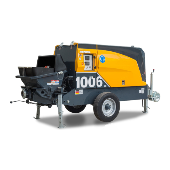
Stationary concrete pump
BSA 1006 D5
Machine no.
210111697
2021-08-09
The paper on which this document is printed is 100% chlorine-free
© Putzmeister Concrete Pumps GmbH 2021
Advertisement
Table of Contents

Related Manuals for Putzmeister BSA 1006 D5


Summary of Contents for Putzmeister BSA 1006 D5
- Page 1 Translation of the original instructions Stationary concrete pump BSA 1006 D5 Machine no. 210111697 2021-08-09 The paper on which this document is printed is 100% chlorine-free © Putzmeister Concrete Pumps GmbH 2021...
- Page 2 Britain Carrwood Road GB−Chesterfield +44−1246−26 00 77 PMUK www.putzmeister.co.uk Derbyshire S41 9QB Türkiye +90−282−735−1000 Putzmeister Makine Sanayi ve Tic. A. pm@putzmeister.com.tr G.O. Pa a Mah. Nam k Kemal Bulvar No: 6 +90−282−738−1001 www.putzmeister.com.tr 59500 Çerkezköy / TEK +1−262−886−3200 Putzmeister America pmr@putzam.com...
- Page 3 Translation of the original instructions الأصلي التشغيل دليل ترجمة Превод на оригиналното „Ръководство за работа“ Překlad originálního návodu k obsluze Oversættelse af den originale driftsvejledning Übersetzung der Originalbetriebsanleitung Μετάφραση του πρωτότυπου των οδηγιών λειτουργίας Traducción del manual de instrucciones original Originaalkasutusjuhendi tõlge Alkuperäisen käyttöohjeen käännös Traduction de la notice originale...
- Page 4 Operating Instructions 210111697_2021-08-09_en...
- Page 5 Table of contents . . . Table of contents Guide to the Operating Instructions ........1 — 1 Foreword ......................... 1 — 3 Icons and symbols ......................1 — 4 1.2.1 Layout of warning notices ....................1 — 5 Safety regulations ..............2 —...
- Page 6 Table of contents . . . 2.3.10 Accessories and attachments ..................2 — 15 2.3.11 Changes to the machine ....................2 — 15 Exclusion of liability ......................2 — 16 Personnel ........................2 — 16 2.5.1 Requirements ........................2 — 16 2.5.2 Qualifications ........................
- Page 7 Table of contents . . . 2.12.5 Procedure in storms ......................2 — 36 2.12.6 Concreting in cold weather ....................2 — 37 2.13 Delivery line systems ...................... 2 — 37 2.13.1 Suitable delivery lines ..................... 2 — 37 2.13.2 Securing delivery lines ....................
- Page 8 Sound pressure level ...................... 3 — 20 3.5.2 Sound power level ......................3 — 21 Electromagnetic compatibility (EMC) ................3 — 21 Putzmeister Connected Services ..................3 — 21 3.7.1 Remote Service ....................... 3 — 22 3.7.2 Machine Cockpit ......................
- Page 9 Table of contents . . . 3.16.4 Filling the lubricant reservoir ................... 3 — 62 3.16.5 Additional lubrication procedure ..................3 — 63 3.17 Flushing water pump ....................... 3 — 64 3.17.1 Structure .......................... 3 — 64 3.17.2 Function .......................... 3 —...
- Page 10 Table of contents . . . 5.4.5 Hand signal for reverse pumping ..................5 — 19 5.4.6 Hand signal for stopping the pump ................. 5 — 19 Filling the water box ......................5 — 19 Pumping .......................... 5 — 20 5.6.1 Dangers during pumping ....................
- Page 11 In this chapter you will find notes and information that will help you use this document. If you have any queries, please write to us in confidence at the address given below, or contact the relevant branch or works agency. Putzmeister Concrete Pumps Abteilung Kundendienst Max-Eyth-Straße 10 72631 Aichtal, Germany...
- Page 12 1 — 2 Operating Instructions 210111697_2021-08-09_en...
- Page 13 Guide to the Operating Instructions Foreword These Operating Instructions aim to help you to familiarise yourself with the machine and make use of its intended applications. The Operating Instructions contain important information on how to operate the machine safely, properly and economically. Observing these instructions helps to avoid danger, to reduce repair costs and downtimes and to increase the reliability and service life of the ma‐...
- Page 14 Violations will result in a claim for damages. All rights reserved in the event of the grant of a patent, utility model or design. © Putzmeister Concrete Pumps GmbH 1994 Icons and symbols The following icons and symbols are used:...
- Page 15 Guide to the Operating Instructions Icon/symbol/ Meaning designation Fault rectification – Instructions to be carried out in accordance with fault messages. View additional steps. For example, “Contact a qualified electrician”. The requirements or tools outlined below must be ✓ met or available. Tests or inspections have been passed.
- Page 16 Guide to the Operating Instructions WARNING Indicates a dangerous situation in which an accident resulting in se‐ rious or fatal injuries may occur. ▶ After identifying the risk, instructions are set out which are inten‐ ded to avoid or remedy the risk. CAUTION There is a risk of injury to the entire body, however there is no risk of serious or fatal injuries.
- Page 17 Safety regulations These safety regulations correspond to the “Terms, definitions, re‐ quirements” and “Starting up and working with the machine” sections in the VDMA (German Engineering Federation) brochure “Safety manual for concrete delivery and placing machines”. Here you will find a summary of the most important safety regulations. This chapter is therefore particularly useful for providing initial and ba‐...
- Page 18 2 — 2 Operating Instructions 210111697_2021-08-09_en...
- Page 19 Safety regulations Definition of terms The terms used in this Safety Manual are explained below, along with descriptions of the requirements placed on specific groups of people. 2.1.1 Machine For the purposes of this Safety Manual, concrete delivery and placing machines are defined as: ●...
- Page 20 Safety regulations 2.1.6 Truck mixer For the purposes of this Safety Manual, truck mixers are defined as vehicles with mixing equipment for transporting concrete. 2.1.7 Delivery line systems For the purposes of this Safety Manual, delivery line systems are de‐ fined as self-contained pipes or hoses in which concrete is pumped from the concrete pump to the placement site.
- Page 21 Safety regulations 2.1.13 Signaller and other auxiliary personnel Persons instructed by the site management to help the machine oper‐ ator in his work if the latter is unable to observe all areas of operation and danger zones. Signallers must be able to independently evaluate all dangerous situations which may occur when working with a con‐...
- Page 22 Safety regulations 2.1.19 Place of work, working area, danger zone 2.1.19.1 Mobile machines Figure 1: Example 2.1.19.2 Stationary machines Figure 2: Example 2 — 6 Operating Instructions 210111697_2021-08-09_en...
- Page 23 Safety regulations Pos. Designation Explanation Place of work (during Machine operator In normal operation, with the remote con‐ pumping operations) trol Hoseman At the end hose in the danger zone Signaller In the machine operator's range of vision Auxiliary personnel As machine operators of the manual placing system Truck mixer driver...
- Page 24 Safety regulations 2.1.19.3 Place of work The place of work is the area in which people must remain in order to carry out the work. Place of work – machine operator The machine operator's place of work is with the remote control when the pump is in operation.
- Page 25 Safety regulations Impermissible working area Because of their high manoeuvrability, some placing booms can also be shifted into positions for which they are not designed. This may overload or damage the placing boom. Placing booms must therefore (Impermissible only be moved within the permitted working area. working area P.
- Page 26 Safety regulations Machine All the time the vehicle is in operation, there is a risk of injury on and below the machine from moving parts and bursting delivery lines or hydraulic hoses, as well as a risk of falling on slippery surfaces or steps.
- Page 27 Safety regulations You must also observe the Operating Instructions and comply with the intervals and conditions for inspections (particularly retesting) and maintenance work in order to operate the machine within the limits of its proper use. 2.2.1 Retesting (safety inspection) After initial commissioning of the machine, the operational safety of the machine must be checked regularly by a subject expert.
- Page 28 Safety regulations Inspect after every 500 operating hours or 1 year, whichever is soonest. The interval is repeated after every retest. ● Machines more than 10 years old: Inspect after every 250 operating hours or 1 year, whichever is soonest. The interval is repeated after every retest. The day of initial commissioning in accordance with the handover re‐...
- Page 29 Safety regulations 2.3.2 Lifting loads The placing boom must never be used for lifting loads. 2.3.3 Removing obstacles The placing boom must not be used under any circumstances to re‐ move obstacles. This would overload the placing boom, causing dam‐ age and endangering people.
- Page 30 Safety regulations 2.3.6 Impermissible end hose There must be no couplings, spouts, discharge stops or other items fixed to the outlet end of the end hose unless they are approved by the manufacturer. 2.3.7 Impermissible working area During pumping operations, the end hose must not be moved back‐ wards beyond the vertical axis of rotation of the placing boom.
- Page 31 Safety regulations In addition to this, additional impermissible working areas exist, de‐ pending on the machine model and manufacturer, which are descri‐ bed in the Operating Instructions. 2.3.8 Climbing the placing boom It is prohibited to climb the placing boom, to stand on top of it or to misuse it as a working platform or climbing aid.
- Page 32 Safety regulations Exclusion of liability Where the manufacturer's delivery conditions are agreed, liability will be as described in the provisions there. The manufacturer is not liable for damage in cases specified there. Unless the responsibility of the manufacturer, the warranty will be in‐ validated in the following situations in particular: ●...
- Page 33 Safety regulations ● They must have demonstrated their competence to the operator. ● They can be expected to reliably execute the tasks with which they are charged. The operating personnel must not wear loose garments or jewellery, including rings. Long hair which is not tied back must be covered by a hair net.
- Page 34 Safety regulations As the operator, you must always make sure that the Operating In‐ structions are available. The Operating Instructions and check book must always be kept to hand at the site of use of the machine (in the tool compartment or container provided for this purpose). As the operator, you must have personnel working on the machine confirm in writing their knowledge, understanding and application of the Operating Instructions and Safety Regulations and Safety Man‐...
- Page 35 Safety regulations 2.6.3 Other regulations The current regulations for concrete delivery and placing machines as issued by: ● The legal authorities in your country ● The national supervisory bodies ● The responsible commercial liability insurance company. Personal protective equipment To reduce the risk to life and limb, personal protective equipment must be used by the operating personnel whenever necessary or re‐...
- Page 36 Safety regulations Symbol Meaning Hearing protectors Hearing protectors protect you against the noise generated in the vicinity of the machine when you are standing close to it. (DIN EN 352-1:2003; Hearing protectors - General requirements - Part 1: Earmuffs or DIN EN 352-3:2003;...
- Page 37 Safety regulations Symbol Meaning Safety harness When working at heights, use climbing aids and platforms that are intended for this pur‐ pose and comply with the safety regulations or wear a safety harness. Relevant national regulations must be observed. (DIN EN 361:2002; Personal protective equip‐ ment against falls from a height - Full body harnesses;...
- Page 38 Safety regulations Set all the control and monitoring devices to the zero position before you change the mode of control (control block, control console or re‐ mote control). Never put the remote control down when the machine is ready for op‐ eration.
- Page 39 Safety regulations Rated voltage [V] Minimum clearance [m] up to 1 kV 1 kV up to 110 kV 110 kV up to 220 kV 220 kV up to 380 kV unknown rated voltage The specified clearances are minimum requirements. You must ob‐ serve any greater clearances that may be specified in the country of use.
- Page 40 Safety regulations 2.9.4 Highvoltage warning devices According to the current rules of engineering, highvoltage warning de‐ vices do not meet a safety standard which enables minimum clearan‐ ces to highvoltage lines that are smaller than the required minimum clearances to be used. Previous experience has shown that highvolt‐ age warning devices cannot make all situations in working proce‐...
- Page 41 Safety regulations 2.9.6 Earthing in the event of electrostatic charging Working in the vicinity of transmitters (radio transmitter, etc.) can re‐ sult in faults in the radio remote control system and dangerous electri‐ cal charges in the machine. Persons who bridge the charged parts to the earth suffer life-threatening electrification on contact.
- Page 42 Safety regulations (Setup site P. 2 — 27) section. Please also observe the 2.10.2 Stationary placing booms Stationary placing booms can be erected on tubular columns, lattice booms or other base structures. The base/structural elements to which the base structure is fixed must be able to withstand the forces and moments transferred via the base structure, as specified in the manufacturer’s information.
- Page 43 Safety regulations The transport vehicle and machine must be marked to conform with the road traffic regulations in the country concerned if they are to use the public highway. (Driving P. 2 — 31) section. Please also observe the 2.11 Mobile machines 2.11.1 Setup site...
- Page 44 Safety regulations 2.11.2 Supporting ground Find out the load-bearing capacity of the supporting ground. The site management will be able to state the permitted ground pressure. If the load-bearing capacity is unknown, assume the that worst case scenario applies. The supporting ground must be level and even. If necessary, set up a level surface on top of the uneven ground.
- Page 45 Safety regulations 2.11.3 Corner bearing loads The corner bearing load is stated on each support leg. This value must always be legible. The load supported by each support leg is conically diffused in the ground at an angle of 45 °. Safe clearance to the pits and slopes must be maintained, and such clearance must be determined in accord‐...
- Page 46 Safety regulations turer with a device which allows secure erection with a reduction in support. Check the corresponding notes in this regard in the operat‐ ing instructions. Do not carry out more than one movement at a time. If a movement is stopped, the entire volume of fluid is available for the remaining movements, and can increase their speeds.
- Page 47 Safety regulations 2.11.5 Driving When preparing the machine for driving, you must perform the follow‐ ing tasks in particular: ● The placing boom must be folded in fully and positioned on the placing boom support provided. ● The support legs and support feet must be fully retracted and se‐ cured.
- Page 48 Safety regulations Do not drive across uphill or downhill gradients. Be aware of the ele‐ vated position of the truck's centre of gravity when travelling on a slope and on ascending or descending routes. Always adapt your travelling speed to the prevailing conditions on sloping terrain. Observe national road traffic regulations.
- Page 49 Safety regulations Use only appropriate means of transport and lifting equipment of ade‐ quate load-bearing capacity. Lifting equipment, lifting tackle, support trestles and other auxiliary equipment must be reliable and safe in op‐ eration. Only load the machine on stable loading ramps of adequate load- bearing capacity.
- Page 50 Safety regulations tact, for example, because you are changing workplace, you must switch off the remote control. If there is no visual contact, for exam‐ ple, because the construction site is unclear, signallers MUST be used, and must remain in contact with the machine operator using suitable means, and have visual contact with the site of concrete placement, work areas and danger zones, and the machine.
- Page 51 Safety regulations The manufacturer has indicated such impermissible working areas by the use of warning signs and information plates on the machine and appropriate notes in the Operating Instructions. 2.12.2 End hose The end hose must hang freely each time you start pumping, when you start pumping again after blockages, and during cleaning proce‐...
- Page 52 Safety regulations 2.12.3 Guiding the end hose ergonomically The hoseman must guide the end hose in such a way that prevents excess spraying of concrete, and so that concrete is directed precise‐ ly into the site of concrete placement. Control the placing boom so that the hoseman can guide the end hose without power consumption.
- Page 53 Safety regulations Tower cranes on construction sites generally have wind speed meas‐ uring equipment, enabling you to find out the wind speed at any time. If no wind speed measuring equipment is available, you can ask the nearest meteorological office what the wind speed is, or estimate the wind speed using the following rule of thumb: ●...
- Page 54 Safety regulations 2.13.2 Securing delivery lines Delivery lines, delivery hoses, end hoses and couplings must be se‐ curely fastened and secured to prevent spontaneous opening. 2.13.3 Leak tightness and blockages Regularly force water through the delivery line under operating pres‐ sure to check that the system is watertight.
- Page 55 Safety regulations 2.13.4 Opening delivery lines Delivery lines must not be opened or tapped off while they are pres‐ surised. Concrete exiting under pressure can cause injury. The con‐ crete column must be depressurised by reverse pumping before the delivery line is opened. Never bend over the coupling when you are working.
- Page 56 Safety regulations 2.13.8 Devices for shutting off, diverting and cleaning During operation, there is a risk of being crushed and of injury by shearing. Hydraulically driven devices are generally supplied with power by the hydraulic system of a machine. For this reason, there must always be a line of sight between the devices and the machine fitted with the control unit.
- Page 57 Safety regulations 2.14.3 Remote control You must always carry the remote control on your person when the machine is ready for operation. Only in this way can it be guaranteed that you can press the EMERGENCY STOP in the event of an BUTTON emergency situation.
- Page 58 Safety regulations Do not insert any objects (shovel handle, trowel, etc.) into moving ma‐ chine components. Such objects could become trapped and dragged into the machine. They might then hit you or be torn from your hands and cause you injury. 2.14.5 Constant observation of the machine You should be constantly observing the machine for any damage or...
- Page 59 Safety regulations The preferred methods for cleaning the delivery line are reverse pumping or forced cleaning with water. The agitator must be switched on during reverse pumping. Otherwise, the concrete flowing back into the hopper can bend the agitator shaft. Use a catch basket, pipe cleaning head and wash-out ball for forced cleaning to prevent any water from flowing into the formwork.
- Page 60 Safety regulations manufacturer's instructions regarding use and safe handling. Wear protective clothing. Always rinse off cleaning agent thoroughly with clean water; do not allow puddles to form. Do not use sea water or other water containing salt for cleaning pur‐ poses.
- Page 61 Safety regulations ● A catch basket must be fastened at the end of the delivery line and a wash-out adaptor must be fitted on the head of the delivery line. The catch basket and washout adaptor must fit the delivery line system.
- Page 62 Safety regulations 2.15.4 Protection against water Water spraying on the machine from random directions has no dam‐ aging effect. The electrical system is protected against spray water, but is not waterproof. You must close/seal all openings into which water/steam/cleaning agent must not penetrate for safety or functional reasons before cleaning the machine with water or a steam jet (high-pressure clean‐...
- Page 63 General technical description This chapter describes the structure and method of operation of the components on this machine. Please note that possible (optional) ad‐ ditional equipment is also described. Refer to the machine card to check whether you have the particular additional equipment or not. 3 —...
- Page 64 3 — 2 Operating Instructions 210111697_2021-08-09_en...
- Page 65 General technical description Overviews Item Designation Pressure gauge for hydraulic fluid filter wear Pressure gauge for hydraulic fluid pressure Control cabinet (Control cabinet P. 3 — 26) Core pump operating panel (Core pump operating panel P. 3 — 27) Cable remote control (Cable remote control P.
- Page 66 General technical description Item Designation Coolant filler opening (with vent valve) Coolant fill level indicator Fuse box Battery Item Designation Fluid drain cock Hydraulic fluid filler opening Fill level indicator for hydraulic fluid reservoir Water pump/agitator lever Flushing water pump: (Flushing water pump P.
- Page 67 General technical description Item Designation Fuel filler opening Centralised lubrication system (Centralised lubrication system P. 3 — 61) Safety equipment This chapter contains the following information about the safety equipment: ● Overview ● Intervals for inspections ● Description of individual assemblies 3.2.1 Overview Item...
- Page 68 General technical description Item Designation Protective grille (on the water box) Agitator safety cutout (Agitator safety cutout P. 3 — 11) Spray guard The positions of the EMERGENCY STOP buttons are listen in the following chapter: (EMERGENCY STOP function P. 3 — 8) 3.2.2 Safety components WARNING...
- Page 69 General technical description Read the “EB00-5-xxxxx-xxxx” sheet to ensure that you are aware of the SRPs fitted on the machine. Figure 3: SRP marking Item Designation Left Spare parts sheet Right Spare part packaging BP15_013_1412DE 2 Figure 4: Extract from an example spare parts sheet Item Designation Asterisk “*”...
- Page 70 Item Designation Hourglass – SRP service life Example spare parts sheet “EB00-5-xxxxx-xxxx” (3) for every safety-related part Putzmeister specifies a service life (SRP). The SRPs must be replaced once this service life has elapsed. 3.2.4 Plates Plates on the machine warn operators of dangers that cannot be pre‐...
- Page 71 General technical description Area Action Core ● The agitator stops pump ● The transfer tube stops ● The delivery pistons stop ● The variable main pumps swing into the idling posi‐ tion Drive ● Motor speed drops to idle ● It is no longer possible to set the motor speed elec‐ trically Table 1: Actions triggered by the EMERGENCY STOP function 3.2.5.2...
- Page 72 General technical description WARNING Risk of death due to a defective EMERGENCY STOP button The machine cannot be switched off quickly enough in the event of impending danger if the EMERGENCY STOP button is defective. This means that the machine is no longer safe to use. ▶...
- Page 73 General technical description ⇒ All safety actions are carried out immediately. Area Action Core ● The agitator stops pump ● The transfer tube stops ● The delivery pistons stop ● The variable main pumps swing into the idling posi‐ tion Drive ●...
- Page 74 General technical description 3.2.6.1 Structure The agitator safety cutout is located on the hopper. The installation lo‐ cation on the hopper varies. Figure 6: Function check of the agitator safety cutout (RSA) Item Designation Reading head (on the hopper – example illustration) Green and red LEDs Transponder (on the grille) 3.2.6.2...
- Page 75 General technical description The LEDs on the evaluation device indicate the following: ● Green LED: ● Flashes for 8 seconds during the initialisation process ● Lights up during normal operation when the grille is closed ● Flashes when the grille is open ●...
- Page 76 General technical description 2. Close the grille. You can deactivate the agitator safety cutout on the core pump oper‐ ating panel. (Core pump operating panel P. 3 — 27) 3. Press the “Deactivate agitator safety cutout” BUTTON ➙ The stroke correction is started up. ➙...
- Page 77 General technical description Figure 7: Agitator safety cutout function check 2. Open the grille. Safety ac‐ ● The agitator stops. tions ● The transfer tube stops. Process- ● The delivery pistons move to the end position and related ac‐ then stop. tions Table 4: Actions of the agitator safety cutout ⇒...
- Page 78 General technical description 3.2.7 Grille The grille is a passive safety function (separating protective device). The bar spacing is selected in such a way that it allows concrete with defined particle sizes to flow into the hopper. The bars are subject to natural wear.
- Page 79 General technical description Figure 8: Bars of the grille 1. Measure the width (W) and height (H) of the bars in an area with high wear, preferably in the middle of the grille. 2. Measure the width (W) and height (H) of the bars in an area with the least wear (edge of the grille).
- Page 80 3.3.3 Operating altitude Putzmeister must be contacted if the machine is to be used at an alti‐ tude greater than that given here. The standard reference level is the European standard elevation zero (NHN).
- Page 81 General technical description Machine rating plate Figure 9: Rating plate Machine data Item Designation Manufacturer's address Machine model Designation of the machine Machine number Chassis number marking Year of manufacture not present 3 — 19 210111697_2021-08-09_en Operating Instructions...
- Page 82 General technical description Item Designation Operating data Item Designation Maximum fluid pressure in the hydraulic system Maximum delivery pressure Delivery line cross section: Outside diameter x wall thickness not present Gross weight not present If specific details do not apply to a machine, the relevant fields are blank.
- Page 83 Putzmeister Connected Services This machine transfers non-personal machine data to Putzmeister in real time. The machine data is saved and aids Putzmeister in the de‐ velopment of new products. The operator can object to the transfer of operating data at any time.
- Page 84 General technical description For questions, please e-mail: connectedservices@putzmeister.com Putzmeister also offers the following services: ● Remote Service ● Machine Cockpit 3.7.1 Remote Service The After Sales Service personnel and your dealer can identify prob‐ lems more quickly using the “Remote Service” web app.
- Page 85 General technical description Term Description Diesel Oxidation Catalyst (DOC) Catalytic converter which burns off carbon monoxide in exhaust = diesel oxidation catalyst gas to form carbon dioxide Diesel Particle Filter (DPF) ● Filter which separates soot from exhaust gas = diesel particle filter ●...
- Page 86 General technical description WARNING Risk of burning ▶ Stay clear of the exhaust after treatment system – particularly during and after regeneration. The motor speed needs to be increased to start regeneration. For technical reasons, the motor speed can only be increased when the core pump is switched off.
- Page 87 General technical description Colour definition – LEDs in the button Each on the operating panels of this machine has four integra‐ BUTTON ted LEDs that indicate the status of a function as follows: Figure 10: Example illustration: Switch support leg monitoring on/off button Item Designation Red LED...
- Page 88 General technical description 3.10 Control cabinet You can control the functions of the machine from the control cabinet and obtain information about the machine’s operating state. Operating elements Item Designation Display (Display P. 3 — 29) Core pump operating panel (Core pump operating panel P.
- Page 89 General technical description 3.11 Core pump operating panel The core pump operating panel is located at the control cabinet. LEDs are integrated in each button on the operating panel. (Colour definition – LEDs in the button P. 3 — 25) The operating panel is divided into columns of three buttons each.
- Page 90 General technical description Button Function Forward pumping On/Off Reverse pumping On/Off Core pump off Table 6: Column 2 Button Function Increasing output Reducing output Vibrator On/Off Table 7: Column 3 Button Function Increase motor speed Reduce motor speed ergonic Output-Control On/Off Table 8: Column 4 3 —...
- Page 91 General technical description Button Function Agitator On/Off – for forward pumping Agitator On/Off – for reverse pumping Loading the last saved core pump parameters Table 9: Column 5 3.12 Display The software is shown on the display. You can operate the software with the display’s operating elements.
- Page 92 General technical description Pos. Description Function ● Select submenu ● Select value Direction key ● Change value ● Open selected submenu ok button ● Confirm input System LED ● When lit: Power supply is switch‐ ed on ● When flashing: System is switch‐ ed on 3.13 Software...
- Page 93 General technical description Navigation bar (only in main menu) Menu content Function bar 3.13.1.1 Navigation bar The navigation bar only appears in the main menu. You can use the navigation bar to navigate to the submenus. Symbol Menu User settings Core pump Motor Inputs and outputs...
- Page 94 General technical description 3.13.1.2 Menu content Item Designation Hydraulic fluid temperature Core pump status Current output (in m /h and in %) Display of an EMERGENCY STOP Fuel tank fill level Motor speed of rotation Display of an agitator safety cutout The core pump status is indicated by the following symbols: Status dis‐...
- Page 95 General technical description 3.13.1.3 Function bar You can switch functions on and off or switch them over in the func‐ tion bar. The availability of functions depends on the equipment of the machine and the open menu. The symbol lights up green if a function is active. Status dis‐...
- Page 96 General technical description 3.13.2 “User settings” menu In this menu, you can change machine settings to adapt the machine behaviour to difficult conditions. Symbol Description Lubrication interval of the centralised lubrication sys‐ ● 200 d: Set interval in strokes ● 55 a: Performed strokes Switching between rod side and piston side feed Rod side Piston side...
- Page 97 General technical description Colour Description Inactive Active Setting changed but not yet saved Table 10: Setting status If the core pump sensors are faulty, they can activate the emergency stroke time. A standard value is entered for the stroke time. You can change the emergency stroke time to adjust it to the pump‐...
- Page 98 General technical description Symbol Description Hydraulic fluid temperature Current output in % Current output in m You can adjust the output using the remote control. (Cable remote control P. 3 — 47) The core pump condition is indicated by a simplified pictogram. The pictogram contains the following information: ●...
- Page 99 General technical description (Core pump operating panel P. 3 — 27) Symbol Description Centralised lubrication system Lubrication procedure inactive Lubrication procedure active Centralised lubrication system fault Vibrator No vibrator connected Vibrator Off Vibrator On Additional functions You can switch functions on and off or switch them over in the func‐ tion bar.
- Page 100 General technical description Status dis‐ Description play Compressor on/off Fill-level sensor in the hopper on/off Fill-level sensor off Fill-level sensor on Hopper filled Fill-level sensor on Hopper empty Core pump stopped automatically Switchover behaviour of the transfer tube Automatic configuration Hard switchover Soft switchover Working light on/off...
- Page 101 General technical description The following operating parameters are displayed: Symbol Description Speed Power supply Fuel indicator Double display ● Fill level (ratio) ● Consumption ( l/h) Fill level low Cooling water temperature Engine oil pressure Table 12: Operating parameters The following information is displayed on the status of the exhaust af‐ ter treatment: 3 —...
- Page 102 General technical description Symbol Description Remaining runtime of the regeneration Regeneration active Table 13: Status of the exhaust after treatment Symbol Description Start regeneration Stop regeneration Observe the notes on exhaust after treatment! Table 14: Function bar in the “Motor” menu The machine is equipped with exhaust after treatment.
- Page 103 General technical description This list is only displayed if there are faults. 3.13.5 “Inputs and outputs” menu This menu is used for fault analysis when contacting the customer service. This menu is used to display the status of the connections on the con‐ trol cabinet.
- Page 104 General technical description Colour Description Inactive/not present Active Fault Description pmSCP_C Control system software version pmSCP_D Display software version Table 16: Software versions Symbol Description Reset transfer tube position values Table 17: Function bar in the “Inputs and outputs” menu 3.13.6 “Operating data”...
- Page 105 Symbol Description Reset daily meter (trip) (press and hold for several seconds) 3.13.7 Messages In case of doubt, contact the Putzmeister customer service. Message Description Corrective measure Messages active in the “Motor” Check the “Motor” menu for active messages. menu Table 18: Messages from the entire machine 3 —...
- Page 106 General technical description 3.13.7.1 Entire machine Message Description Corrective measure (EMERGENCY STOP function P. 3 — 8) EMERGENCY STOP active Table 19: Messages from the entire machine 3.13.7.2 Motor Motor messages are triggered by a fault signal from the motor. The fault signal is sent from the motor to the control cabinet.
- Page 107 General technical description Message Description Corrective measure Cooling water fill level low Top up cooling water Rectify the cause See operating instructions from the motor manu‐ facturer (included) Fuel filter blocked Repair fuel filter Table 20: General Message Description Corrective measure DPF free DPF full: Level 1 Start regeneration during the next cleaning opera‐...
- Page 108 General technical description Message Description Corrective measure Exhaust after treatment normal Fault in exhaust after treatment Contact motor manufacturer’s customer service system Where applicable, have the displayed SPN fault Next escalation level in no more numbers to hand than three hours Fault in exhaust after treatment Stop site use system...
- Page 109 General technical description Message Description Corrective measure Fault on core pump sensors Contact customer service (Agitator safety cutout P. 3 — 11) Agitator safety cutout active Table 23: Core pump 3.14 Cable remote control 3.14.1 Structure LEDs are integrated in the buttons on the cable remote control. (Colour definition –...
- Page 110 General technical description Button Function ● Deactivating the EMERGENCY STOP ● Horn Loading the last saved core pump parameters Forward pumping On/Off Reverse pumping On/Off Increasing output Reducing output Increase motor speed Reduce motor speed 3.14.2 Safely using the remote control 1.
- Page 111 General technical description 5. If required, call in other persons who have visual contact to the site of concrete placement, the machine and to work areas and danger zones. You need to set down the remote control? 1. Switch off the remote control. 2.
- Page 112 General technical description 3.15.2 Function The core pump is powered by a diesel engine or an electric motor via a hydraulic fluid pump. The delivery pistons are connected hydrauli‐ cally with each other via the drive cylinders. They run in counter stroke.
- Page 113 General technical description 3.15.4 Water box 3.15.4.1 Structure Figure 12: Structure of the water box Item Designation Seal Grille Water outlet Water box 3.15.4.2 Function The water in the water box cools the core pump cylinders. 3 — 51 210111697_2021-08-09_en Operating Instructions...
- Page 114 3. You must rectify damage to the delivery piston/drive cylinders immediately. Putzmeister accepts no warranty claims for dam‐ age to the machine resulting from failure to properly observe the maintenance regulations.
- Page 115 General technical description 3.15.4.4 Draining the water box CAUTION Risk of burning due to hot water in the water box 1. Exercise the necessary caution when working on the water box. 2. Allow the water to cool before carrying out maintenance work 1.
- Page 116 General technical description 3.15.5 Agitator 3.15.5.1 Structure Item Designation Mixing paddle Mixer shaft Agitator drive 3.15.5.2 Function The hopper is equipped with a hydraulically driven agitator. The agitator performs the following functions: ● Improving the fill level of the delivery cylinders ●...
- Page 117 General technical description Forward pumping: The fill level in the delivery cylinders should be high. The conveyed material is moved to the delivery cylinders by the agitator. Reverse pumping: The delivery cylinders should be emptied. The conveyed material is moved away from the delivery cylinders by the agitator and mixed in the hopper.
- Page 118 General technical description (Core pump operating panel P. 3 — 27) 2. Switch the agitator to the required function. ⇒ 3. Press the selected function again to stop the agitator. 3.15.6 Vibrator The vibrator is bolted onto the hopper grille. It displaces the grille when there is vibration, thereby preventing bridges from forming on the grille, particularly in the case of very stiff concrete.
- Page 119 General technical description 3.15.7 Magnetic switch distributor casing The distributor casing for the magnetic switches is located on the drive cylinders of the concrete pump. There are two magnetic switches on each drive cylinder of the core pump, one at the rod side and one at the piston side. 3.15.7.1 Structure Figure 14: Structure of the magnetic switch distributor casing...
- Page 120 General technical description 3.15.7.3 Indicator lights Indicator light Magnetic switch status lights up briefly during switch‐ Magnetic switch is OK over does not light up during switch‐ Magnetic switch, connector or over lead are defective, replace at the earliest opportunity lights up continuously Magnetic switch, connector or lead are defective, remove con‐...
- Page 121 General technical description 3.15.8 Magnetic switch connector The connector for the magnetic switch has one yellow and one green LED. These LEDs indicate the status of the connector and the mag‐ netic switch. Figure 15: Magnetic switch connector Item Designation Green and yellow LEDs Connector Magnetic switch...
- Page 122 General technical description Yellow LED Magnetic switch status lights up briefly during switch‐ Magnetic switch is fully function‐ over does not light up during switch‐ Magnetic switch is defective, re‐ over place at earliest opportunity lights up continuously Magnetic switch is defective. Disconnect the magnetic switch connector (because otherwise it is not possible to switch over)
- Page 123 General technical description 3.16 Centralised lubrication system 3.16.1 Structure Item Designation Lubricant reservoir Air bleeder Lubricant pump Grease gun Lubricant distributor Mixer shaft bearings Stransfer tube bearing Upper switch cylinder bearings Lower switch cylinder bearings Switching shaft bearings 3.16.2 Function The centralised lubrication system is automatic.
- Page 124 General technical description The following assemblies are lubricated by the centralised lubrication system: ● Core pump 3.16.3 Maintaining the centralised lubrication system 1. Check at regular intervals whether lubricant is emerging at all lu‐ brication points. 2. Check the main lines and lubrication point lines for damage. 3.
- Page 125 General technical description CAUTION Risk of injury Risk of being drawn in or risk of crushing when reaching into the lu‐ bricant reservoir while the lubricant pump is pumping. ▶ Never reach into the lubricant reservoir while the lubricant pump is running.
- Page 126 General technical description You can trigger a manual lubrication at the following operating posi‐ tions: ● In local operation: ● At the core pump operating panel 3.17 Flushing water pump 3.17.1 Structure Figure 16: Flushing water pump structure Item Designation Water supply Water outlet (connection for cleaning gun)
- Page 127 General technical description 3.17.3 Switching on the water pump WARNING Risk of death from pumping incorrect functional fluids 1. Do not pump foodstuffs. 2. Only pump water. 3. Use only commercially available cleaning agents. WARNING Risk of injury 1. Hold the cleaning gun and lance firmly in your hand or ensure that the cleaning gun is located in a secure holder.
- Page 128 General technical description Prerequisites: ✓ Water supply is connected (Connecting the water supply P. 4 — 16) ✓ Water temperature: 5–60 °C ✓ Water supply shut-off valve is open ✓ Water pump drain cock is connected ✓ Cleaning gun is connected to the water outlet of the water pump ✓...
- Page 129 General technical description 1. Turn the lever to the agitator. ⇒ The water pump stops. 2. Operate the cleaning gun. ⇒ The water pressure in the water pump is dumped. ➙ You have switched off the water pump. You can drain the water pump. 3.17.5 Draining the flushing water pump The flushing water pump may be damaged by frost.
- Page 130 General technical description 2. Remove the water supply hose. 3. Remove the water outlet hose. 4. Open the drain cock. ➙ You have dewatered the water pump. ➙ The water pump is protected against frost damage. 3 — 68 Operating Instructions 210111697_2021-08-09_en...
- Page 131 Transport, support and connection 4 — 1 210111697_2021-08-09_en Operating Instructions...
- Page 132 4 — 2 Operating Instructions 210111697_2021-08-09_en...
- Page 133 Transport, support and connection Transporting 4.1.1 Loading WARNING Risk of death The machine can fall from the lifting equipment if it is lifted incorrect‐ 1. Check the gross weight of the machine before loading it. 2. Only use suitable and checked lifting eyes for lifting the ma‐ chine.
- Page 134 Transport, support and connection Item Designation Attachment bracket Lifting points for lifting tackle 2. Hook four-cable lifting tackle to the four lifting points. 3. Tension the lifting tackle. ⇒ The four cables are attached at an angle of max. 45° to the perpendicular.
- Page 135 Transport, support and connection Figure 17: Marked eyes for lashing If you are preparing the machine for transport: 6. Lash the machine down to the truck bed of the transport vehicle or into the container using suitable auxiliary devices. 7. Remove the lifting tackle. ➙...
- Page 136 Transport, support and connection The approach route to the concrete pump must be sufficiently firm for it to be driven over by truck mixers regardless of the weather condi‐ tions. 4. Walk the approach route before you drive along it. 5.
- Page 137 Transport, support and connection WARNING Risk of death due to the machine slipping Risk of injury to various parts of the body by crushing, impact and shearing caused by the machine slipping. If the supporting ground has insufficient load-bearing capacity or there is inadequate clear‐ ance from pits or slopes, the machine will no longer be stable.
- Page 138 Transport, support and connection 4.2.1.2 Safe clearance from pits The safe clearance A ● for loose, backfilled soil is A ≥ 2 × pit depth T. ● for compact, undisturbed soil A ≥ 1 × pit depth T. A 2 T A 1 T Figure 19: Safe clearance A ▶...
- Page 139 Transport, support and connection 4.2.1.3 Supporting ground WARNING Risk of death due to a loss of machine stability Risk of death and injury to various parts of the body by crushing, im‐ pact and shearing caused by loss of machine stability because the supporting ground has insufficient load-bearing capacity.
- Page 140 Transport, support and connection Figure 21: Only support on level supporting ground 4.2.2 Support structure Item Designation Rear support feet Crank Rotating support Forward support foot Towing ring 4 — 10 Operating Instructions 210111697_2021-08-09_en...
- Page 141 Transport, support and connection Item Designation Lever for support foot control (for each side) Enabling valve for support foot control Rear support feet Symbol Meaning Lower support foot Raise support foot 4.2.3 Extend supports Prerequisites: ✓ You have read the safety regulations. (Safety regulations P.
- Page 142 Transport, support and connection In order to support the machine with the rotating support, you must fold the support wheel down. 2. Fold the support wheel down. You can raise or lower the rotating support using the crank on the drawbar.
- Page 143 Transport, support and connection ⇒ The drawbar moves downwards. ⇒ The rear of the machine moves upwards. 2. Place support plates underneath the rear support feet. 3. Pull the spring pins out of the stop pins on the rear support feet. The support feet may move downwards on their own as soon as you pull out the stop pin.
- Page 144 Transport, support and connection ⇒ The front of the machine moves upwards. ⇒ The machine is supported on the rear support feet. ⇒ The load on the wheels is relieved. 4.2.3.3 Folding down the support foot If the forward support foot is folded up, you need to fold it down. Figure 22: Forward support foot in the folded down position Item Designation...
- Page 145 Transport, support and connection ➙ You have folded down the support foot. 4.2.3.4 Lowering the forward support foot 1. Place a support plate underneath the forward support foot. 2. Pull the spring pin out of the stop pin on the forward support foot. 3.
- Page 146 Transport, support and connection 4.2.4 Retracting the supports Prerequisites: ✓ You have read the safety regulations. (Safety regulations P. 2 — 1) ✓ There is no conveyed material in the hopper. ✓ You have cleaned the machine. (Cleaning P. 5 — 29) 1.
- Page 147 Transport, support and connection Designation Value Required volumetric flow rate 80 l/min The following factors may impede the water supply: ● Water pump drain cock is open ● Bend or pinched hose ● Damage to the hose or coupling ● Hose diameter too small ●...
- Page 148 4 — 18 Operating Instructions 210111697_2021-08-09_en...
- Page 149 Operation This chapter describes a site use, as an example. 5 — 1 210111697_2021-08-09_en Operating Instructions...
- Page 150 5 — 2 Operating Instructions 210111697_2021-08-09_en...
- Page 151 Operation Test run The machine may have been damaged in your absence. You will be well prepared if you check the condition of the machine before driving to the construction site. 1. Make sure that all safety devices are fitted. 2.
- Page 152 Operation Examples of separating protective devices: ● Grille ● Spray guard ● Protective grille ● Heat protection plate 1. Replace damaged separating protective devices. 2. Check the machine for visible damage. For some assemblies, simply rectifying external damage is insuffi‐ cient.
- Page 153 Operation 5.2.2 Draining the hydraulic fluid reservoir NOTICE Corrosion damage in the hydraulic system caused by excessive wa‐ ter content Corrosion damage can lead to increased wear or even to machine damage. ▶ Drain the condensation each time before starting work. NOTICE Environmental pollution caused by incorrect condensation removal The drained liquid is an environmentally damaging mixture of water...
- Page 154 Operation 5.2.3 Checking functional fluids WARNING Hazardous auxiliary materials or functional fluids Possible poisoning, chemical burns or irritation 1. Take note of the safety data sheets for the auxiliary materials and functional fluids used. 2. Wear personal protective equipment. 3. Personnel who work with auxiliary materials or functional fluids must be trained in handling them.
- Page 155 Operation ● Fuels (for combustion engines) ● Motor oil ● Cooling water ● Hydraulic fluid ● Lubricant of the centralised lubrication system 1. Allow the functional fluids to cool. 2. Check the fill levels of all functional fluids. 3. Refill the functional fluids if necessary. There must always be a little fuel in all fuel tanks to prevent corro‐...
- Page 156 Operation 4. Deactivate the EMERGENCY STOP. ➙ You have switched on the machine. You can carry out the function checks. 5.2.5 Warming up the hydraulic fluid Starting up the machine requires a warm-up period if the temperature of the hydraulic fluid is below 0 °C. Prerequisites: ✓...
- Page 157 Operation 5.2.7 Deactivating the agitator safety cutout WARNING The agitator can start up unexpectedly 1. Do not tamper with the agitator safety cutout. 2. The machine must only be operated if the agitator safety cutout is intact. The core pump is secured against unexpected restarts. When starting up the machine and when the agitator safety cutout has been activa‐...
- Page 158 Operation 5.3.1 Checking the EMERGENCY STOP function Each time before the machine is used WARNING Risk of death due to a defective EMERGENCY STOP button The machine cannot be switched off quickly enough in the event of impending danger if the EMERGENCY STOP button is defective. This means that the machine is no longer safe to use.
- Page 159 Operation ⇒ All safety actions are carried out immediately. Area Action Core ● The agitator stops pump ● The transfer tube stops ● The delivery pistons stop ● The variable main pumps swing into the idling posi‐ tion Drive ● Motor speed drops to idle ●...
- Page 160 Operation Figure 25: Agitator safety cutout function check 2. Open the grille. Safety ac‐ ● The agitator stops. tions ● The transfer tube stops. Process- ● The delivery pistons move to the end position and related ac‐ then stop. tions Table 25: Actions of the agitator safety cutout ⇒...
- Page 161 Operation 5.3.3 Checking the pump functions Only use the pump if you cannot detect any visible damage to the pump or adjacent components. 5.3.3.1 Checking the switchover ▶ Check for an unimpeded switchover function of the delivery pis‐ tons and the transfer tube at various engine speeds and positions of the output controller.
- Page 162 Operation ⇒ The delivery pistons move to their end positions. ⇒ Stroke correction is automatic and is complete when both de‐ livery pistons come to a halt (may be seen in the water box). 5.3.3.4 Checking the stroke time Measure the machine stroke time under no load, i.e. without concrete. 1.
- Page 163 Operation 5.3.4.1 Check the contamination indicator The pressure gauge is located near the control cabinet. Figure 27: Pressure gauge for filter condition Prerequisites: ✓ The water box is filled with water. ✓ The machine is switched on. ✓ The temperature of the hydraulic fluid is at least 50 °C. 1.
- Page 164 Operation Figure 28: Checking and replacing the pressure filter 2. Press the red button on the pressure filter. ⇒ The red button remains down. The red button pops back out? ▶ Replace the pressure filter. Hand signals for pumping operations Clear hand signals must be agreed between the machine operator and the signaller before start of work.
- Page 165 Operation 5.4.1 EMERGENCY STOP hand signal Figure 29: EMERGENCY STOP ▶ With your arms stretched out to the side, move both arms quickly up and down. 5.4.2 Hand signal for stopping Figure 30: Stop ▶ Stretch both arms out to the side. 5 —...
- Page 166 Operation 5.4.3 Hand signal for increasing output/start of delivery Figure 31: Increasing output or start of delivery 1. Point the thumb on one hand upwards. 2. Hold the palm of the other hand over it. 5.4.4 Hand signal for reducing output Figure 32: Reducing output 1.
- Page 167 Operation 5.4.5 Hand signal for reverse pumping Figure 33: Reverse pumping ▶ With one arm crooked, place your elbow into the palm of your other hand. 5.4.6 Hand signal for stopping the pump Figure 34: Stop pump ▶ Hold both arms above your head with your hands clasped togeth‐ Filling the water box Prerequisites: 1.
- Page 168 Operation ⇒ The water level in the water box is above the cylinder open‐ ings. 4. Stop the water supply. 5. Fit the lid on the water box. Pumping Prerequisites: ✓ You have started up the machine. (Starting up P. 5 — 3) ✓...
- Page 169 ● Properties of freshly-mixed concrete ● Properties and conditions of freshly-mixed concrete when pumping ● Guide to avoid faults ● Specifications and regulations of the “Technical Regulations” You can request a copy of this brochure from the Putzmeister After Sales department. 5.6.3 Mixing together Correct mixing together of concrete influences pumping.
- Page 170 Operation 5.6.4 Operating the agitator The agitator and water pump are mutually locked. Only one of the functions can be active at any one time. Prerequisites: ✓ You have familiarised yourself with the agitator functions. (Function P. 3 — 54) You can supply the agitator or water pump with hydraulic fluid using a lever.
- Page 171 Operation You must start to pump with a cement-water mixture (grout) in the following cases: ● Long delivery line (longer than 50 m) ● New delivery line ● Delivery line that has not been used for a long time Prerequisites: ✓...
- Page 172 Operation 5. Pump the concrete slowly into the delivery line. ⇒ The process of starting to pump with thin concrete is comple‐ ted when the two sponge balls and a solid concrete stream ex‐ it from the end hose. 5.6.6 Starting the pumping process Prerequisites: ✓...
- Page 173 Operation 4. Avoid breaks when pumping concrete with a low water retentivity (tendency to bleeding) as the vibrations can segregate the con‐ crete. 5. In the case of lengthy breaks in pumping, pump the concrete back into the hopper. 6. Mix up the concrete again before starting to pump once more. 7.
- Page 174 Operation ● leavings in the transfer tube and delivery line ● unsuitable concrete composition ● segregated concrete ● set concrete 1. In the event of blockages, pump the concrete immediately back into the agitator hopper and mix it up. 2. Switch back over to forward pumping if the delivery cylinders and transfer tube are automatically switching over perfectly once again.
- Page 175 Operation Your machine has a thermoelectrical cutout. The machine is automat‐ ically switched off if the hydraulic fluid temperature exceeds the fol‐ lowing limit: 90 °C To prevent the machine being switched off due to overheating of the hydraulic fluid: 1.
- Page 176 Operation 1. Continuously change the water in the water box if the hydraulic fluid temperature continues to rise. 2. Locate the cause of the hydraulic fluid overheating and rectify this cause. Additional cooling Figure 39: Additional cooling ▶ If additional cooling is required, direct the water jet towards the drive cylinder and piston rods in the drive cylinder.
- Page 177 Operation Cleaning WARNING Moving parts in the hopper 1. Do not reach into the hopper. 2. Do not insert any objects through the grille. 3. Never operate the concrete pump without the grille in place. 4. Check the wear to the grille at regular intervals. WARNING The agitator can start up unexpectedly 1.
- Page 178 Operation WARNING Risk of injury from the grille slamming shut Risk of the upper body being crushed or suffering impact due to the grille slamming shut. ▶ Always open the grille as far as it will go (i.e. to its end position) and then secure it.
- Page 179 Operation Concrete residues deposited around the wear ring can impair its func‐ tion. Therefore, thorough rinsing of the wear ring is important after work is finished, as long as the pump will not be used again within the next 30 to 60 minutes. 5.7.1 Observe the notes on cleaning 1.
- Page 180 Operation 5.7.2.1 Pre-fitting the catch basket The use of the catch basket is recommended when cleaning with pressurised water, to ensure that the delivery line is sealed off, and no water can escape. Figure 40: Fitted catch basket Item Designation Coupling Catch basket (closed pipe section) Spring pin (on both sides)
- Page 181 Operation WARNING The delivery line is pressurised 1. Only open the wash-out port lid when the delivery line is dep‐ ressurised. 2. Make sure that the T delivery pipe is designed for the delivery pressure specified on the concrete pump rating plate. Item Designation T delivery pipe with wash-out port...
- Page 182 Operation Figure 41: Wash-out adaptor structure Item Designation Pressure gauge Guard bracket Connection for pressurized water or compressed air Shut-off valve for connection Pressure dump elbow Dump cock 1. Close the dump cock. 2. Close the connection for pressurised water or compressed air. 5 —...
- Page 183 Operation 5.7.2.4 Preparing cement bags When it comes to cleaning the delivery line with pressurised water, rolled-up cement bags soaked in water are a tried and tested cleaner. The cement bags prevent the washing water entering into the con‐ crete, rinsing it out and causing a blockage. Figure 42: Rolled-up cement bags 1.
- Page 184 Operation Figure 44: Cleaning in the hopper Item Designation Adhesive tape marking 2. Measure the hose length required on the outside of the transfer tube. The hose spray nozzle should be located just in front of the wear ring, so that concrete residue is washed out of the area of the wear ring and seal ring when the spray is set.
- Page 185 Operation 2. You should ideally use the concrete residue sheet from Putzmeis‐ ter. 3. Place the sheet underneath the hopper. 4. Open the cleaning flap on the hopper. ⇒ The concrete flows into the sheet. You can use a construction site crane to transport the sheet to the placement site.
- Page 186 Operation CAUTION Rebound from cleaning gun 1. Ensure that the cleaning gun is located in a secure holder be‐ fore you start up the high-pressure water pump. 2. Never lock the lever on the cleaning gun. NOTICE Material damage The water jet of the high-pressure water pump can damage surfa‐ ces.
- Page 187 Operation ▶ Turn the lever to the water pump symbol. ⇒ → 5.7.5 Clean the delivery line There are a number of options for cleaning a delivery line. Some of the factors affecting which cleaning method you use include how the concrete pump has been used and what equipment you have availa‐...
- Page 188 Operation The delivery line has been disconnected from the concrete pump. The concrete residue is forced for‐ wards from the start of the delivery line to the site of concrete placement using an external force (com‐ pressed air or water under pressure). Cleaning is from the start of the delivery line to the site of con‐...
- Page 189 Operation Delivery line Cleaning method Riser Compressed only with spe‐ cial equipment Water under pressure Suction clean‐ Downpipe Compressed only with spe‐ cial equipment Water under pressure Suction clean‐ 5.7.5.2 Suction cleaning Suction cleaning is the simplest and least hazardous cleaning meth‐ 1.
- Page 190 Operation Insert the wash-out sponge Figure 45: Cleaning accessories Item Designation Sponge pig Sponge cube Sponge ball Wash-out pig ▶ Push a water-soaked wash-out sponge into the end hose. Reverse pumping the concrete WARNING Risk of injury Concrete can spray out of the hopper during reverse pumping. 1.
- Page 191 Operation ⇒ The concrete and the wash-out sponge are pumped back through the delivery line. The concrete is not pumped back? The delivery line is too long for suction cleaning. ▶ Clean the delivery line by “Cleaning with pressurised water”. Tracking the wash-out sponge Figure 46: Tracking the wash-out sponge in the delivery line 1.
- Page 192 Operation Trapping the wash-out sponge Figure 47: Trapping the wash-out sponge with the pin at the wash-out port lid. 1. Unlock the movable pin on the wash-out port lid and push it into the delivery line. 2. Switch the core pump to reverse pumping. ⇒...
- Page 193 Operation 5.7.5.3 Cleaning with pressurised water Cleaning with pressurised water is more thorough than suction clean‐ ing, but also requires more effort. The core pump or an auxiliary pump can be used for cleaning with pressurised water. Figure 48: High-pressure water cleaning Item Designation Gate valve...
- Page 194 Operation 4. Switch the concrete pump off after one to two strokes. ⇒ The pressure in the delivery line is dumped. Inserting the wash-out sponge 1. Soak two to three wash-out sponges in water. 2. Push the wash-out sponges into the concrete pump's wash-out port.
- Page 195 Operation Figure 49: Tracking the wash-out sponge 5. Tap on the delivery line with a piece of hardwood (hammer han‐ dle) just ahead of the cleaning port during the washing out proc‐ ess. ⇒ If there is concrete in the delivery line, the tapping generates deep, dull sounds.
- Page 196 (catch basket) unless strictly necessary. 6. When cleaning the delivery line with compressed air, do not clean towards the concrete pump hopper. Putzmeister accepts no liability for damage caused by incorrect im‐ plementation of compressed air cleaning. Prerequisites: ✓...
- Page 197 Operation Figure 50: Compressed air cleaning Item Designation Gate valve Catch basket “Wash-out tower” delivery line 1. Close the gate valve for the concrete pump. ⇒ The concrete flows into the connected wash-out tower or con‐ tainer. 2. Switch the pump to “Reverse pumping”. 3.
- Page 198 Operation ⇒ You have prepared the “Wash-out tower” delivery line. Figure 51: Placing wash-out sponges in the wash-out adaptor Item Designation Wash-out adaptor Delivery line on the boom tip Concrete 8. Place two wash-out sponges in the wash-out adaptor. 9. Remove the end hose from the boom tip. 10.
- Page 199 Operation Figure 53: Filling the wash-out adaptor with compressed air Item Designation “Compressed air” connection Pressure gauge 15. Connect the compressed air supply to the “Compressed air” con‐ nection. 16. Open the “Compressed air” connection. WARNING Risk of blockage 1. Dump the pressure in the delivery line if the pressure gauge on the wash-out adaptor indicates an increased air pressure.
- Page 200 ▶ When restarting, switch the concrete pump off first, and then back on again. 5.7.6.1 Draining concrete residue Figure 54: Lay the sheet down 1. Place the Putzmeister concrete residue sheet under the hopper. 5 — 52 Operating Instructions 210111697_2021-08-09_en...
- Page 201 Figure 55: Hoisting the concrete away You may only hoist a maximum of 0.5 m of concrete (approx. 1200 kg) using the Putzmeister concrete residue sheet. 5. Hoist away the concrete in the concrete residue sheet. 5.7.6.2 Draining the water box...
- Page 202 Operation 1. Place a container underneath the water outlet point of the water box. 2. Remove the lid. 3. Open the water outlet. ⇒ The water drains out. 4. Slowly move the delivery pistons until the water has drained com‐ pletely.
- Page 203 Operation 5.7.6.4 Spraying out the delivery cylinder Prerequisites: ✓ You have familiarised yourself with the warning notices for clean‐ ing: (Cleaning P. 5 — 29) ✓ You have marked a water hose. (Marking the water hose P. 5 — 35) Figure 56: Spray out the transfer tube valve and delivery cylinder in cases where the concrete pump is running backwards slowly 1.
- Page 204 Operation ⇒ The delivery cylinders are rinsed out alternately. ⇒ Clear water will emerge once the delivery cylinders are cleaned. 6. Rinse out the feeder container carefully with a water hose. 5.7.6.5 Checking the wear ring Item Designation Transfer tube Thrust ring Wear ring Spectacle wear plate...
- Page 205 Operation 5.7.6.6 Cleaning the gap between the transfer tube bearing and the transfer tube After each pumping operation, you must clean the transfer tube bear‐ ing thoroughly to prevent any concrete encrustation in the transfer tube bearing. Figure 58: Example illustration of cleaning the transfer tube bearing Item Designation S transfer tube...
- Page 206 Operation 3. Carefully spray out the surfaces to be cleaned of the transfer tube bearing. 4. After cleaning, immediately grease the transfer tube bearing via the lubrication points provided. ⇒ Grease visibly emerges from between the transfer tube and transfer tube bearing. 5.
- Page 207 Operation 5.7.6.7 Close hinged elbow Figure 59: Hinged elbow lock Item Designation Lettering “0” or milling Retaining bolt for hinged elbow Milling for recognizing the correct mounting position. Hinged elbow Wedge Tie rod for retaining bolt Spring pin (2) must be screwed onto the tie rod (6) as The retaining bolt (1) upwards).
- Page 208 Operation (2) is firmly seated. 1. Check that the retaining bolt (2) . 2. Check the installation position of the retaining bolt (4) with the chock (5) . 3. Lock the hinged elbow (5) with the spring pin (7) . 4.
- Page 209 Operation 10. Spray the metal components with an anticorrosion agent or a re‐ lease agent. 5.7.9 Switching off the water pump Switch off the water pump after every site use. The agitator and water pump are mutually locked. Only one of the functions can be active at any one time.
- Page 210 Operation If required due to the climatic conditions to which the stored ma‐ chine is exposed, you must carry out these preservation measures at shorter intervals. 5.8.1 Document the measures taken to preserve value ▶ Document the date that the machine is placed into storage and the value preservation measures that are carried out.
- Page 211 Interrupting the run-down time will cause a fault in the control unit. This fault is shown continuously in the display, which means that you run the risk of overlooking other faults. Putzmeister will not ac‐ cept warranty claims for engine damage and operating errors that result from a failure to switch off the engine according to the instruc‐...
- Page 212 Operation 3. Connect the central control unit (CCU) to a supply voltage at six- monthly intervals. 4. Protect electrical components against moisture and corrosion. 5.8.4 General measures to preserve the value of the water assembly 1. Empty the water tank and the water lines. 2.
- Page 213 Glossary This chapter illustrates the control system symbols (icons for concrete pumps) and explains the abbreviations and technical terms that are used in Putzmeister Operating Instructions. B — 1 210111697_2021-08-09_en Operating Instructions...
- Page 214 B — 2 Operating Instructions 210111697_2021-08-09_en...
- Page 215 Glossary Symbols for concrete pumps in accordance with German Mechanical Engineering Association Standard (VDMA -24119) 3701 3713 3725 5008 6012 7005 3702 3714 4001 6001 6013 7006 3703 3715 4002 6002 6014 7007 3704 3716 4003 6003 6015 7008 3705 3717 4004 6004...
- Page 216 Glossary 8005 10005 10017 12001 12013 12025 8006 10006 10018 12002 12014 12026 8007 10007 10019 12003 12015 12027 8008 10008 10020 12004 12016 12028 8009 10009 10021 12005 12017 12029 9001 10010 10022 12006 12018 12030 9002 10011 10023 12007 12019 12031...
- Page 217 Glossary 12037 12043 12049 12055 13004 14003 12038 12044 12050 12056 PM13005 15001 12039 12045 12051 12057 PM13006 15002 12040 12046 12052 13001 PM13007 15003 12041 12047 12053 13002 14001 12042 12048 12054 13003 14002 Figure 62: “General” symbols 3 Symbols key: General Item Designation...
- Page 218 Glossary Item Designation 3717 Changeover 3718 Stroke pulse for change-over 3719 Stroke correction 3720 Change-over delay 3721 Screw conveyor 1 anticlockwise rotation 3722 Screw conveyor 1 clockwise rotation 3723 Screw conveyor 2 anticlockwise rotation 3724 Screw conveyor 2 clockwise rotation 3725 Screw conveyor 4001...
- Page 219 Glossary Item Designation 6014 Filter element 6015 Rod side 6016 Piston side 6017 Hydraulic fluid filter water level stop (PM symbol) 6018 Hydraulic fluid filter water level warning (PM symbol) 6019 Hydraulic fluid filter contamination warning (PM symbol) 7001 Spotlights 7002 Lighting 7003...
- Page 220 Glossary Item Designation 10005 Acknowledge cooling water excess temperature 10006 Engine oil pressure 10007 V-belt failure 10008 Increase speed, reduce speed 10009 Speed 10010 Speed sensor 10011 Increase speed 10012 Reduce speed 10013 Engine air filter 10014 Electric motor in general 10015 Silent 10016...
- Page 221 Glossary Item Designation 12011 Vibrator Off 12012 Vibrator 12013 Potentiometer 12014 Off - On 12015 12016 12017 Fast (e.g. acceleration) 12018 Normal (e.g. acceleration) 12019 Compressor 12020 Compressor on - off 12021 Motor vehicle fuse 12022 Cable drum 12023 Operating hours meter 12024 Operating position 12025...
- Page 222 Glossary Item Designation 12045 Circuit 2 12046 Circuits 1+2 12047 High-pressure limit 12048 Flap/closure closed 12049 Flap/closure open 12050 Generator 12051 Boom on cradle 12052 Manual operation 12053 Electrical levelling 12054 See Operating Instructions 12055 Wear measurement 12056 Water 12057 Overhead roll-and-fold boom 13001 Power takeoff...
- Page 223 Glossary Agitator safety cutout The agitator safety cutout (RSA) stops hazardous concrete pump movements when the grille is opened. (Grille P. B — 14) (Automatic Piston Pull P. B — 11) Automatic Piston Pull A ball valve is installed in the drive cylinder.
- Page 224 Glossary (Transfer tube P. B — 18) Check book The check book is part of the doc‐ umentation accompanying the ma‐ chine: Checklist with confirmation of the legally required checks for con‐ crete pumps and placing booms Corner bearing load The corner bearing load is the force which the machine exerts on each corner of its tilting edge.
- Page 225 Glossary Ergonic ® Registered brand name for all Putzmeister components which control concrete pumps and plac‐ ing booms. Ergonic Output Control Microprocessor supported system for economic operation of the con‐ crete pump. For the output set by the machine operator, only the minimum required engine speed will be set automatically.
- Page 226 Glossary Functional fluids Hydraulic fluid, fuel, brake fluid, battery acid etc. Grille The grille is the cover grille for the hopper. The grille has two functions: ● It only allows grain up to a par‐ ticular size to pass through ●...
- Page 227 Operating equipment Battery, filters PEDOC Putzmeister Electronic Documen‐ tation (Putzmeister Electronic Documen‐ tation P. B — 16) Piston end-of-travel positioning Piston end-of-travel positioning (KEP) is a function for replacing the delivery pistons.
- Page 228 Glossary Putzmeister Electronic Docu‐ Documentation accompanying the mentation machine on CDROM Reversal The concrete is sucked back from the delivery line into the hopper. Rod side (Agitator safety cutout P. B — 11) Service operation Use the “Pumping operation-Serv‐ ice operation” toggle switch on the control cabinet to switch over be‐...
- Page 229 Glossary Sound pressure level The sound pressure level is a log‐ arithmic measurement for the rela‐ tive loudness of the sound [dB (A)]. The sound produced by the ma‐ chine is measured at a fixed dis‐ tance and height at several meas‐ uring points.
- Page 230 Glossary Test reading The measurement record is part of the documentation accompanying the machine: List of the machine setting values Tilting edge The tilting edge surrounds the ma‐ chine. The machine topples over as soon as its centre of mass is outside the tilting edge.
- Page 231 Index Index In this chapter, you will find the most important keywords and the number(s) of the page(s) on which they appear. This index of key words is in alphabetical order. P. 5 — 9 Checking the functions P. 6 — 10 P.
- Page 232 Index P. 5 — 59 Close hinged elbow Document the measures taken to preserve value P. 5 — 62 P. 3 — 25 Colour definition – LEDs in the button P. 5 — 52 Draining concrete residue P. 2 — 3 Concrete pump P.
- Page 233 Index P. 3 — 8, 3 — 12, 3 — 22, 3 — 50, 3 — 51, P. 2 — 24 Function Highvoltage warning devices 3 — 54, 3 — 57, 3 — 61, 3 — 64 P. 2 — 10 Hopper P.
- Page 234 Index P. 3 — 59 P. 3 — 42 Magnetic switch connector “Operating data” menu P. 3 — 57 P. 3 — 26 Magnetic switch distributor casing Operating elements P. 3 — 30 P. 2 — 17 Main menu Operating Instructions ...
- Page 235 P. 3 — 17 Pumping water Service life P. 3 — 21 P. 4 — 11 Putzmeister Connected Services Setting up the machine P. 2 — 25, 2 — 27 Setup site P. 2 — 5 Signaller and other auxiliary personnel P.
- Page 236 Index P. 2 — 9 Support legs and support feet P. 2 — 29 P. 5 — 8 Supports Warming up the hydraulic fluid P. 4 — 10 P. 5 — 33 Support structure Wash-out adaptor P. 3 — 66, 5 — 61 P.
- Page 237 Translation of the original instructions Stationary concrete pump BSA 1006 D5 Machine no. 210111697 2021-08-09 The paper on which this document is printed is 100% chlorine-free © Putzmeister Concrete Pumps GmbH 2021...
- Page 238 Carrwood Road PMUK GB−Chesterfield +44−1246−26 00 77 www.putzmeister.co.uk Derbyshire S41 9QB Türkiye +90−282−735−1000 pm@putzmeister.com.tr Putzmeister Makine Sanayi ve Tic. A. G.O. Pa a Mah. Nam k Kemal Bulvar No: 6 +90−282−738−1001 www.putzmeister.com.tr 59500 Çerkezköy / TEK Putzmeister America +1−262−886−3200 pmr@putzam.com...
- Page 239 Translation of the original instructions الأصلي التشغيل دليل ترجمة Превод на оригиналното „Ръководство за работа“ Překlad originálního návodu k obsluze Oversættelse af den originale driftsvejledning Übersetzung der Originalbetriebsanleitung Μετάφραση του πρωτότυπου των οδηγιών λειτουργίας Traducción del manual de instrucciones original Originaalkasutusjuhendi tõlge Alkuperäisen käyttöohjeen käännös Traduction de la notice originale...
- Page 240 Service Instructions 210111697_2021-08-09_en...
- Page 241 Table of contents . . . Table of contents Guide to the Service Instructions ..........1 — 1 Foreword ......................... 1 — 3 Icons and symbols ......................1 — 4 1.2.1 Layout of warning notices ....................1 — 5 Safety regulations ..............2 —...
-
Page 242: Table Of Contents
Table of contents . . . Maintenance ................4 — 1 Maintenance intervals ..................... 4 — 3 Residual risks during maintenance, inspection and repair work ........4 — 5 4.2.1 Personal protective equipment ..................4 — 5 4.2.2 Personnel requirements ....................4 —... - Page 243 In this chapter you will find notes and information that will help you use these Service Instructions. If you have any queries, please write to us in confidence at the address given below, or contact the relevant branch or works agency. Putzmeister Concrete Pumps Abteilung Kundendienst Max-Eyth-Straße 10 72631 Aichtal, Germany...
- Page 244 1 — 2 Service Instructions 210111697_2021-08-09_en...
- Page 245 Guide to the Service Instructions Foreword The Service Instructions contain important information about the maintenance of the machine. Observing these instructions helps to avoid danger, to reduce repair costs and downtimes and to increase the reliability and service life of the machine. The Service Instructions must be supplemented by the relevant na‐...
- Page 246 Offenders will be held liable for the payment of damages. All rights reserved in the event of the grant of a patent, utili‐ ty model or design. © Putzmeister Concrete Pumps GmbH 1994 Icons and symbols The following icons and symbols are used:...
- Page 247 Guide to the Service Instructions Icon/symbol/ Meaning designation View additional steps. For example, “Contact a qualified electrician”. The requirements or tools outlined below must be ✓ met or available. Tests or inspections have been passed. This indicates a tip, helpful note or additional in‐ formation regarding machine maintenance, envi‐...
- Page 248 Guide to the Service Instructions WARNING Indicates a dangerous situation in which an accident resulting in se‐ rious or fatal injuries may occur. ▶ After identifying the risk, instructions are set out which are inten‐ ded to avoid or remedy the risk. CAUTION There is a risk of injury to the entire body, however there is no risk of serious or fatal injuries.
- Page 249 Safety regulations These safety regulations correspond to the “Maintenance and special work” section in the VDMA (German Engineering Federation) bro‐ chure “Safety manual for concrete delivery and placing machines”. ““Safety manual for concrete delivery and placing machines””. The safety regulations in the Operating Instructions must also be fol‐ lowed for all maintenance and special work.
- Page 250 2 — 2 Service Instructions 210111697_2021-08-09_en...
- Page 251 2.1.1 Exclusion of liability We state here expressly that Putzmeister accepts no liability for dam‐ age arising from incorrect or negligent operation, servicing or mainte‐ nance or as a result of use contrary to the designated use. This state‐...
- Page 252 Safety regulations Use specially designed or otherwise suitable climbing aids and work‐ ing platforms when carrying out assembly work above head height. Never use machine parts as climbing aids. Keep all handgrips, steps, railings, platforms and ladders free from dirt, snow and ice. Carefully secure individual parts and large assemblies to lifting equip‐...
- Page 253 Safety regulations spected by qualified welding personnel. The operator must document the evidence of the formal qualifications of the welder and the quali‐ fied welding personnel. Always attach the earth cable of the welding unit directly to the com‐ ponent which is being welded. The welding current must not flow through hinges, cylinders, etc.
- Page 254 Safety regulations The delivery line was installed without tension with the placing boom in the driving position and can only be replaced without difficulty in this condition. Stresses may be generated on folding if the delivery line is replaced when the placing boom is unfolded. Do not remove the entire delivery line but rather replace the delivery line boom arm by boom arm, for example.
- Page 255 Safety regulations Keep all warning signs and information plates on the machine com‐ plete and in a perfectly legible condition. It is your responsibility as operator to ensure that any warning signs and information plates that have been damaged or rendered illegible are replaced without delay.
- Page 256 Safety regulations If work is to be carried out on live parts, the presence of a second person is required who can switch off the power supply to the ma‐ chine in the event of an emergency. Secure the working area with a red-and-white safety chain and a warning plate.
- Page 257 Safety regulations Always wear your personal protective equipment when carrying out work on the hydraulic system. Escaping fluid is toxic and can pene‐ trate the skin. Injection through the skin is a major medical emergency. In the event of injuries caused by pressurised fluid, inform the company medical officer and call a medical specialist immediately.
- Page 258 Safety regulations The hydraulic system must be properly vented after all maintenance work. Otherwise there is a risk of injury caused by swinging and tele‐ scopic support legs extending rapidly, the placing boom lowering, etc. Open vent valves very carefully until hydraulic fluid starts to escape. You should on no account open vent valves further than necessary or go so far as to remove them.
- Page 259 Safety regulations ing up the engine in enclosed spaces, make sure that there is ade‐ quate ventilation and direct the exhaust gases away from the place of work. Wear personal protective clothing and equipment for all work in which exhaust gases or particles of building material can enter the body through the respiratory passages.
- Page 260 Safety regulations Take care when handling hot functional fluids and consumables (risk of burning or scalding). Have used operating equipment and functional fluids such as filters, batteries, oil, brake fluid, etc. disposed of properly. Used cleaning rags should also be disposed of properly. 2.13 Disposal of the machine To dispose of the machine, you must proceed in accordance with all...
- Page 261 Special operating modes WARNING Risk of death during special operation 1. Only ever use special operating modes if you have received training on these by the manufacturer of the machine. 2. Only ever use special operating modes if you are authorised to do so by the operating company of the machine.
- Page 262 3 — 2 Service Instructions 210111697_2021-08-09_en...
- Page 263 Special operating modes Recovery with onboard equipment You must stop the site use if the on-board electronics fail. The delivery system may become damaged if concrete sets in it. You can recover the machine without support from the on-board electron‐ ics.
- Page 264 Special operating modes 3.1.2 Setting up the pump control system The pump control system is located behind the control cabinet. Item Designation Hydraulics control block of the core pump Figure 1: Hydraulics control block of the core pump Item Designation Switch over the transfer tube Move the delivery pistons “Adjust output”...
- Page 265 Special operating modes WARNING Risk of death due to moving components During emergency operation, moving components may present a danger to personnel. 1. Ensure that nobody is in the danger zone before emergency op‐ eration. 2. Announce the emergency operation of moving components in a clear and timely manner.
- Page 266 Special operating modes 8. Fit the casing in front of the pump control system again following emergency operation. 3 — 6 Service Instructions 210111697_2021-08-09_en...
- Page 267 Maintenance Carry out all specified checks, inspections and maintenance work conscientiously. Otherwise we will refuse any liability or warranty claim. Contact the Putzmeister After Sales department if you have any questions. 4 — 1 210111697_2021-08-09_en Service Instructions...
- Page 268 4 — 2 Service Instructions 210111697_2021-08-09_en...
-
Page 269: Maintenance
Damage caused by inadequate maintenance 1. Have the first After Sales service after 100 operating hours car‐ ried out by a Putzmeister After Sales service engineer. The ma‐ chine operator responsible for the machine should be present during this service. - Page 270 Maintenance Assembly Action Interval daily 500 h annually other Replace hydraulic hoses 6 years (in‐ cluding a stor‐ age period of 2 years) Hydraulic fluid Check the contamination indica‐ ✓ filter Replacing the pressure filter ✓ as required Mixer shaft Check concentricity ✓...
-
Page 271: Residual Risks During Maintenance, Inspection And Repair Work
Maintenance Residual risks during maintenance, inspection and repair work WARNING Risk of injury 1. Wear your personal protective equipment when performing maintenance, inspection and repair work. 2. Always wear a safety helmet and safety footwear. 3. Wear your protective goggles when handling compressed air, corrosive liquids and gases and paints. -
Page 272: Residual Risks
Maintenance 4.2.4 Residual risks During maintenance, inspection and repair work, there are particular risks of an accident, because, for certain activities, protective devices must be removed, for example. There follows a list of residual risks in particular, which may be present during maintenance, inspection and repair work. - Page 273 Maintenance WARNING Risk of injury from the machine starting unexpectedly 1. Put the machine out of service before starting maintenance, in‐ spection and repair work. 2. Secure the machine against unexpected start up (for example, pull out the ignition key and lock it away, or attach a warning plate).
-
Page 274: Specifications For Bolted Connections
Maintenance CAUTION Risk of injury from hot surfaces and functional fluids in the machine Risk of burning to various parts of the body from hot surfaces in the machine's motor area. 1. Do not carry out any service work until the motor, surfaces and functional fluids have cooled down. - Page 275 Maintenance Always replace bolts with bolts of the same size and grade. Replace bolts with adhesive in the locking threads and selflocking nuts after disassembly. 4.4.1 Set screws and nuts ▶ The maximum tightening torques for set screws and nuts can be found in the spare parts list.
-
Page 276: Reassembly Of Walformplus Threaded Unions
Maintenance Figure 2: Tightening the flared screwed joints 1. Using a spanner, tighten the union nut without excessive force. For flanged screw joints and profiled ring joints: 2. Use another spanner to hold the threaded connection in place while doing so. 4.4.3 Reassembly of WALFORMplus threaded unions This section describes what must be borne in mind during reassembly... - Page 277 Maintenance 4.4.3.1 Tightening torques Figure 3: WALFORMplus threaded union setup Item Designation Threaded connection Union nut Pipe Seal The tightening torques are guide values, and only apply to opti‐ mum conditions. The torques may deviate substantially because of tolerance influences, pipes fitted under tension and incorrect lubri‐ cation.
- Page 278 Maintenance WALFORMplus threaded union tightening torques Model [Nm] RAD = pipe external diameter = tightening torque WALFORMplus threaded union tightening torques Model [Nm] RAD = pipe external diameter = tightening torque 4.4.3.2 Fitting WALFORMplus threaded unions For the reassembly of the WALFORMplus threaded union, proceed as follows: 1.
-
Page 279: Functional Fluids
Never use hydraulic fluids or lubricants with additives such as molybdenum. 4.5.1 Hydraulic fluids See alsohttps://www.putzmeister.com/documents/58405/5728115/ CT_4748-2_DE_Hydraulikfluide.pdf The hydraulic system is filled with one of the following hydraulic fluids: ● Mineral hydraulic fluid (HLP) ● Synthetic ester-based biodegradable hydraulic fluid (HEES) ●... - Page 280 (HFC as specified in the 7th Luxembourg Report). Use only Putzmeister hydraulic fluid, material no. 484527, if your ma‐ chine was filled with synthetic ester ex works. We have listed all suitable hydraulic fluids in the table below. Putz‐...
- Page 281 Maintenance Mineral oil Synthetic ester Aqueous solution HEES 46 HFC 46 Initial filling HLP 32 ● Material number: ● Material number: 484527 239879.002 ● Material number: ● Manufacturer: BE‐ ● Manufacturer: 490984 CHEM HYDRO‐ FUCHS HYDRO‐ HLP 46 STAR HEES 46 EEL THERM 46 M ●...
- Page 282 Please contact the manufacturers concerned if you have any queries regarding the suitability and miscibility of hydraulic fluids. You must first consult Putzmeister Department APS if you wish to use hydraulic fluids with viscosity grades other than VG 46 (e.g. at higher ambient temperatures).
-
Page 283: Lubricant Analysis
4.5.4 Lubricant recommendation We have listed all suitable lubricants in the tables below. Putzmeister accepts no liability for the quality of the lubricants listed or for changes in quality made by the lubricant manufacturers without changing the grade designation. - Page 284 Maintenance Gearboxes and drive motors are filled by the respective manufac‐ turer. Maintenance only in accordance with the relevant manufac‐ turer’s specifications. 4.5.4.1 Transmission fluid Rotor gearbox Boom slewing Mixer drum gearbox Transfer gear‐ gear transmission Requirements DIN 51517-3:2018 DIN 51517-3:2018 DIN 51517-3:2018 see spare parts standard...
-
Page 285: Maintenance Work
Maintenance Maintenance work 4.6.1 Carrying out visual checks The following visual checks must be carried out before any mainte‐ nance work. The control deadlines can be found in the overview at the start of this chapter. WARNING Risk of injury from a fire and risk of explosion posed by damaged electrical lines Risk of injury from fire and risk of explosion posed by flash overs from damaged electrical lines, particularly in the case of high levels... -
Page 286: Hydraulic System
Maintenance 4.6.1.2 Electrical system 1. Check that all electrical connections are secure and free from corrosion. 2. Check that the electrical cables have no breaks. 3. Check the insulation on the electrical cables. The electrical system is damaged ▶ Have the damage rectified by a qualified electrician immedi‐ ately. - Page 287 Changing the hydraulic fluid in the hydraulic fluid reservoir NOTICE Machine damage The hydraulic fluid change described does not replace the complete hydraulic fluid change by the Putzmeister Service department. ▶ We recommend having the hydraulic fluid completely changed by the Putzmeister Service department.
- Page 288 Prerequisites: ✓ You have carried out a lubricant analysis. ✓ The Putzmeister Service department has confirmed that changing the hydraulic fluid in the hydraulic fluid reservoir will be sufficient for the measured degree of contamination. ✓ The hydraulic fluid barrels have stood still for some time before the hydraulic fluid is removed from them.
- Page 289 Maintenance Draining the hydraulic fluid 1. Switch off the engine. 2. Press the EMERGENCY STOP BUTTON 3. Check the pressure gauge to ensure that the hydraulic fluid pres‐ sure in the plant has been completely dumped. 4. Remove the from any that are present.
- Page 290 Maintenance Filling the hydraulic fluid reservoir Figure 5: Filling the hydraulic fluid reservoir 1. Use only the hydraulic fluids specified in the lubricant recommen‐ dation. 2. Where possible, fill the hydraulic system using a charging set. 3. Fill the hydraulic fluid reservoir with new hydraulic fluid via the screen in the filler pipe up to the “Maximum”...
- Page 291 Work on the hydraulic system must only be carried out by qualified personnel authorized by Putzmeister. Notify the Putzmeister After Sales department or the dealer or agency that you work with im‐ mediately if you find anything wrong.
- Page 292 Maintenance NOTICE Environmental pollution Lubricants and functional fluids are damaging to the environment. 1. Carefully collect all functional fluids and operating equipment (e.g. used oil, including biologically degradable oil), filters and auxiliary materials. 2. Dispose of these materials separately from other waste. 3.
- Page 293 Maintenance Figure 6: Checking hydraulic hose lines Dark and moist patches on the fitting are external signs of incipient damage. 3. Check the hydraulic hose lines for kinks, cracks or porous surfa‐ ces. 4. Ensure that the hydraulic hose lines are properly routed. Replacing hydraulic hose lines WARNING Risk of injury...
- Page 294 Maintenance Hydraulic hose lines should not be more than six years old, includ‐ ing a storage time of two years. Please note the date of manufac‐ ture on the hydraulic hose lines. The following factors in particular accelerate wear on hydraulic hose lines: ●...
- Page 295 This chapter describes how to replace the following filters: ● Pressure filter NOTICE Material damage Commercially available filter elements do not meet Putzmeister's re‐ quirements. Cleaned filter elements have a lower flow rate than new filter ele‐ ments. 1. Only use original Putzmeister filter elements.
- Page 296 Maintenance The following special tools are required: ● No special tools are necessary. Prerequisites: ✓ The hydraulic fluid barrels have stood still for some time before the hydraulic fluid is removed from them. ✓ You did not roll the hydraulic fluid barrels to the tapping point. Preparing the replacement of the hydraulic fluid filters 1.
- Page 297 Maintenance Figure 8: Setup of the pressure filter Item Designation Filter element Filter housing 1. Unscrew the filter housing. 2. Remove the filter element. 3. Thoroughly clean the filter housing with a clean cloth. 4. Inspect all O-rings and other gaskets in the filter sets, and replace them if damaged.
-
Page 298: Core Pump
Maintenance 4.6.3 Core pump 4.6.3.1 Checking the concentricity of the mixer shaft There are specific risks of accidents associated with maintenance, inspection and repair work. For this reason, read the chapter “Safety regulations” and the description of the residual risks in “Maintenance, inspection and repair work”... - Page 299 Maintenance The agitator drive housing does not turn with the mixer shaft. 3. Switch the machine on. 4. Switch the agitator on. 5. Using the dial gauge, measure how far the agitator drive moves. ⇒ The deviation in concentricity is no more than ±1 mm. 6.
- Page 300 Maintenance Use a K2K grease in accordance with DIN 51502:1990, NLGI Class 2. 1. Repair the centralised lubrication system immediately. Figure 9: Transfer tube and plunger cylinder lubrication diagram 2. Lubricate the lubrication points once to three times daily if no oth‐ er interval is specified.
- Page 301 Maintenance Damage to the delivery pistons must be rectified without delay. Putzmeister accepts no warranty claims for damage to the ma‐ chine resulting from failure to properly observe the maintenance regulations. When replacing the delivery pistons, you must start up and shut down the machine several times.
- Page 302 Maintenance 5. Deactivate the agitator safety cutout. Closing the stroke correction lines Each drive cylinder stroke correction line has a ball valve (KEP) that is fitted open (markings parallel to the line) ex works and is locked against turning. Figure 10: Stroke correction line open Prerequisites: ✓...
- Page 303 Maintenance Figure 11: As-fitted position of the guide washer Item Designation As-fitted position secured against rotation Rotate position You can carry out the following steps at the same time for both ball valves. 1. Remove the bolt on the handle. 2.
- Page 304 Maintenance Figure 12: Turning the handle 7. Close the if both drive cylinders are no longer moving. BALL VALVE Once you have closed the ball valve, it may be that a drive cylinder moves again briefly until both drive cylinders are finally at the me‐ chanical end position.
- Page 305 Maintenance WARNING Moving parts in the water box Risk of crushing and injury by shearing when reaching into the wa‐ ter box 1. Switch off the machine before reaching into the water box. 2. Make sure that no one is working on the water box before switching on the machine.
- Page 306 Maintenance Item Designation Delivery piston Spacer flange 8. Remove the fastening bolts. 9. Remove the retaining rings. 10. Remove the spacer flange. 11. Lever the delivery piston completely out of the delivery cylinder. 12. Remove the old delivery piston. NOTICE Material damage The chrome layer of the delivery cylinder may be damaged.
- Page 307 Maintenance 16. Fit the new delivery piston using the two jacking bolts on the drive piston. 17. Make sure that there are no loose parts in the water box. 18. Step away from the water box. 19. Start the machine up. 20.
- Page 308 Maintenance You can carry out the following steps at the same time for both ball valves. 1. Open the (KEP). BALL VALVE 2. Remove the bolt on the handle. 3. Remove the handle. Figure 15: Turning and securing the ball valve 4.
- Page 309 Maintenance WARNING Risk of injury The S transfer tube could burst once it reaches a high delivery pres‐ sure if the wall thickness of the S transfer tube has decreased be‐ low the minimum dimension, particularly if a blockage has formed. ▶...
- Page 310 You will obtain reliable results for your measurements if you carry out the test with the measuring device recommended by Putzmeister. S transfer tube The minimum wall thickness for the S transfer tube depends on the maximum possible operating pressure.
- Page 311 Maintenance Putzmeister accepts no liability if the wall thickness is less than the minimum wall thickness. As a rule, it is possible to continue pumping with an operating pressure lower than that shown in the graph. Due to dynamic loading during pumping, the delivery line is subjec‐...
- Page 312 Maintenance Figure 17: Overview of the resolver on the switching shaft bearing Item Designation Resolver Connecting cable Marking on the shaft Switch cylinders Switch lever ▶ (1) in such a way that the shaft marking (3) on the Fit the resolver (2) .
- Page 313 Maintenance WARNING Risk of death The hydraulic system is pressurized. Sudden machine movements may occur during operation. 1. Shut the machine down. 2. Secure the machine against unauthorized or accidental starting There are specific risks of accidents associated with maintenance, inspection and repair work.
- Page 314 Maintenance Shutting down the machine WARNING Risk of death 1. Pressure in the hydraulic system may cause sudden machine movements. 2. Before commencing work on the plant, check the pressure gauge to ensure that the hydraulic fluid pressure in the plant has been completely dumped.
- Page 315 Maintenance Dismantling the transfer tube bearing The transfer tube is seated in the rear hopper wall with the transfer tube bearing. Item Designation Pressure connection Pressure flange Hexagon nut Hopper 1. Shut the machine down. 2. Disconnect the delivery line from the pressure connection. 3.
- Page 316 Maintenance Replacing the transfer tube bearing gasket set Figure 18: Bending the grooved ring to make installation easy The mounting position for the gasket set in the transfer tube bear‐ ing can be found in the corresponding spare parts sheet. 1.
- Page 317 Maintenance Assembling the transfer tube bearing Item Designation Pressure connection Pressure flange Hexagon nut Hopper When fitting the transfer tube bearing, note the position of the lubri‐ cation openings. 1. Fit the transfer tube bearing and pressure connection onto the transfer tube outlet.
- Page 318 Maintenance There are specific risks of accidents associated with maintenance, inspection and repair work. For this reason, read the chapter “Safety regulations” and the description of the residual risks in “Maintenance, inspection and repair work” at the start of this chap‐ ter.
- Page 319 Maintenance 9 10 Figure 19: Overview of the switching shaft bearing Item Designation Pulling bore for ball cup Ball cup Hydraulic port Plunger cylinder Retaining plate Retaining plate fastening bolts Switch lever Washer Switching shaft Hexagon nut Switching shaft bearing Fastening bolt for switching shaft bearing (covered) 4 —...
- Page 320 Maintenance Shutting down the machine WARNING Risk of death 1. Pressure in the hydraulic system may cause sudden machine movements. 2. Before commencing work on the plant, check the pressure gauge to ensure that the hydraulic fluid pressure in the plant has been completely dumped.
- Page 321 Maintenance Figure 20: Retaining plate assembly 1. Remove the resolver. 2. Remove any lubrication lines that may be present on the retaining plate and on the switching shaft bearing. 3. Remove the fastening bolts on the retaining plate. 4. Remove the retaining plate. 5.
- Page 322 Maintenance Figure 21: Removing the locking plate Item Designation Plunger cylinder Locking plate Ball cup Pulling bore You can push a plunger cylinder on the piston side out of the ball cup , as shown. If the ball cup is worn, you can screw a bolt into the pulling bore for the ball cup and push out the plunger cylinder with the ball cup.
- Page 323 Maintenance Figure 22: Overview of the switch lever Item Designation Switch lever Pulling bolt 16. Remove the hexagon nut and the washer from the switching shaft. 17. Remove the O-ring from the switching shaft (if present). 18. Pull the switch lever from the switching shaft. Figure 23: Fastening the switching shaft bearing Item Designation...
- Page 324 Maintenance ⇒ The switching shaft bearing is pushed out. 21. Check the gasket set of the switching shaft bearing for wear. 22. Replace the gasket set if necessary. Replacing the switching shaft bearing gasket set Figure 24: Removing the retaining ring 1.
- Page 325 Maintenance Figure 26: Inserting the new grooved ring For the mounting position of the grooved ring in the flanged bear‐ ing, please refer to the accompanying spare parts sheet. 4. Clean the switching shaft bearing. 5. Grease the new gasket set. 6.
- Page 326 Maintenance Replacing the switching shaft bearing wear sleeve and collared wash‐ Figure 27: Overview of switching shaft bearing wear sleeve Item Designation Switching shaft bearing wear sleeve Switching shaft bearing Collared washer Bore 1. Bend the tab of the collared washer downwards. 2.
- Page 327 Maintenance Preparing the switching shaft Item Designation Pressure connection Pressure flange Hexagon nut Hopper 1. Release the transfer tube bearing. 2. Move the flange of the transfer tube bearing approximately 20 mm away from the rear wall of the hopper. 4 —...
- Page 328 Maintenance Figure 28: Undoing the transfer tube bearing Item Designation Rear wall of the hopper Stransfer tube bearing no clearance = incorrect 3. Lift the transfer tube. Figure 29: Lifting the transfer tube 4 — 62 Service Instructions 210111697_2021-08-09_en...
- Page 329 Maintenance Figure 30: Positioning the switching shaft Item Designation Bore: Rear wall of the hopper Bore: Front wall of the hopper Switching shaft 4. Position the switching shaft on the axis between the bore on the rear wall of the hopper and the bore on the front wall of the hop‐ per.
- Page 330 Maintenance ⇒ The switching shaft and the bore on the front wall of the hop‐ per are concentric. Figure 31: Switching shaft aligned concentrically Item Designation Bore on the front wall of the hopper Switching shaft 5. When fitting the switching shaft bearing, note the position of the lubrication openings.
- Page 331 Maintenance Figure 32: Setup of the switching drive Item Designation Switch lever Switching shaft Switching shaft bearing Groove Wear sleeve Flattened tooth 9. Grease the teeth of the switch lever and the switching shaft with “anti-seize agent AS 450 assembly paste” or similar assembly grease.
- Page 332 Maintenance Assembling the transfer tube bearing Item Designation Pressure connection Pressure flange Hexagon nut Hopper ▶ Secure the transfer tube bearing. ⇒ The transfer tube bearing is now touching the rear wall of the hopper. 4 — 66 Service Instructions 210111697_2021-08-09_en...
- Page 333 Maintenance Mounting the switch lever Figure 33: Fitting the switch lever Item Designation Switch lever Switching shaft Oring Washer Hexagon nut The flattened tooth of the switching shaft must align with the centre of the switch lever for the transfer tube to be in the correct position. The centre of the switch lever may be marked with a line.
- Page 334 Maintenance 4. Lubricate the switching shaft bearing using the centralised lubri‐ cation system/grease gun. 5. Fit the plunger cylinders. 6. Replace the lock washers of the fastening bolts on the retaining plate with new ones. 7. Fit the retaining plate . Figure 34: Retaining plate assembly 8.
- Page 335 Maintenance We recommend that the slewing locking mechanism also be re‐ placed when the S transfer tube is replaced. Practical experience has shown that the toothing on the switching shaft and that on the slewing locking mechanism wear together as a result of the forces generated during switchover.
- Page 336 Maintenance WARNING Risk of death The hydraulic system is pressurized. Sudden machine movements may occur during operation. 1. Shut the machine down. 2. Secure the machine against unauthorized or accidental starting Use only suitable lifting equipment for lifting components. Prerequisites: The machine must be shut down.
- Page 337 Maintenance 5. Deactivate the agitator safety cutout. S transfer tube variants Figure 35: S transfer tubes Item Designation S transfer tube with bolted switching shaft S transfer tube with welded switching shaft Whichever variant of S transfer tube is fitted, the recommended pro‐ cedure for dismantling is as described below.
- Page 338 Maintenance (Fitting the switching shaft resolver 3. Remove the resolver. P. 4 — 45) (Replacing the transfer tube 4. Remove the transfer tube bearing. bearing P. 4 — 46) (Replacing 5. Remove the switching shaft bearing (flanged bearing). the switching shaft bearing P. 4 — 51) Figure 36: Removing the mixer shaft 6.
- Page 339 Maintenance 9. Lift the S transfer tube outlet opening first upwards and out. If just the wear sleeve is heavily worn, you can also replace just (Replacing the the wear sleeve and then refit the S transfer tube. transfer tube wear sleeve P. 4 — 84) 10.
- Page 340 Maintenance There are specific risks of accidents associated with maintenance, inspection and repair work. For this reason, read the chapter “Safety regulations” and the description of the residual risks in “Maintenance, inspection and repair work” at the start of this chap‐ ter.
- Page 341 Maintenance Shutting down the machine WARNING Risk of death 1. Pressure in the hydraulic system may cause sudden machine movements. 2. Before commencing work on the plant, check the pressure gauge to ensure that the hydraulic fluid pressure in the plant has been completely dumped.
- Page 342 Maintenance Removing the spectacle wear plate Figure 38: Spectacle wear plate setup Item Designation Plunger cylinder Switch lever Switching shaft Hexagon nut Fastening bolts for spectacle wear plate 1. Shut the machine down. (Fitting the switching 2. Remove the resolver for the transfer tube. shaft resolver P.
- Page 343 Maintenance Figure 39: Pushing the transfer tube to one side 6. Unscrew the eight fastening bolts for the spectacle wear plate. 7. Remove the spectacle wear plate from the hopper. 4 — 77 210111697_2021-08-09_en Service Instructions...
- Page 344 Maintenance Replacing the intermediate rings Figure 40: Intermediate ring setup Item Designation Transition liner Intermediate ring Screw plug Lubrication nipple Grease gun 1. Using a plastic-faced hammer, strike the old intermediate ring a few times from the front. ⇒ Any concrete and grout residue is loosened. 4 —...
- Page 345 Maintenance 2. Replace the screw plug on the underside of the transition liner with the lubrication nipple from the accessories. 3. Connect a grease gun to the lubrication nipple. 4. Pump grease into the lubrication nipple until the intermediate ring is pushed out.
- Page 346 Maintenance Figure 42: Overview of O-rings Item Designation Intermediate ring O-rings O-rings for sealing the delivery cylinder Transition liner 8. Stretch the O-rings over the mounting surface of the new inter‐ mediate ring. 9. Grease the mounting surface of the new intermediate ring. 10.
- Page 347 Maintenance Figure 43: Inserting the O-ring 13. Insert an O-ring in the groove on the front of each intermediate ring. 4 — 81 210111697_2021-08-09_en Service Instructions...
- Page 348 Maintenance Fitting the spectacle wear plate Figure 44: Setup for using the spectacle wear plate Item Designation Fastening bolts on the left and right Spectacle wear plate Fastening bolts at the top and bottom Intermediate ring Oring Hopper wall Clearance 1.
- Page 349 Maintenance If you have a ceramic spectacle wear plate, please contact our Af‐ ter Sales department to enquire about the tightening torques. 3. Using the fastening bolts at the top and bottom, screw on the spectacle wear plate to the appropriate tightening torque. Take care to ensure that the spectacle wear plate does not be‐...
- Page 350 Maintenance NOTICE Damage to the spectacle wear plate If there are lubrication nipples in the pulling bores and these are al‐ so lubricated when lubricating the machine, the intermediate rings will be pushed out. This would cause the spectacle wear plate to become warped.
- Page 351 Maintenance WARNING Risk of death The hydraulic system is pressurized. Sudden machine movements may occur during operation. 1. Shut the machine down. 2. Secure the machine against unauthorized or accidental starting There are specific risks of accidents associated with maintenance, inspection and repair work.
- Page 352 Maintenance Shutting down the machine WARNING Risk of death 1. Pressure in the hydraulic system may cause sudden machine movements. 2. Before commencing work on the plant, check the pressure gauge to ensure that the hydraulic fluid pressure in the plant has been completely dumped.
- Page 353 Maintenance If just the wear sleeve is heavily worn, you can replace it without hav‐ ing to replace the transfer tube. You do not have to remove the trans‐ fer tube to do this. 1. Shut the machine down. (Replacing the transfer tube 2.
- Page 354 Maintenance (1) on the front between the 2. Carefully cut open the welding points (2) and the wear sleeve (3) using an angle transfer tube outlet grinder. Do not damage the transfer tube when doing so. (3) evenly to approx. 140 °C. 3.
- Page 355 Maintenance Fitting the wear sleeve Figure 47: Fitting the wear sleeve Item Designation Wear sleeve Transfer tube outlet (1) is chrome-plated, and therefore must not be The wear sleeve heated unevenly or to too high a temperature. (1) evenly to approx. 140 °C. 1.
- Page 356 Maintenance 4.6.3.11 Replacing the thrust ring and wear ring The following maintenance work information describes replacement of the thrust ring and wear ring of the S transfer tube. The mainte‐ nance intervals can be found in the overview at the start of this chap‐ ter.
- Page 357 Maintenance Use only suitable lifting equipment for lifting components. Prerequisites: The machine must be shut down. The steps required to achieve this are detailed below. Use the remote control here. Shutting down the machine WARNING Risk of death 1. Pressure in the hydraulic system may cause sudden machine movements.
- Page 358 Maintenance Removing the thrust ring and wear ring 1. Shut the machine down. 2. Remove the transfer tube bearing. ⇒ (Replacing the transfer tube bearing P. 4 — 46) 3. Remove the resolver from the switching shaft. ⇒ (Fitting the switching shaft resolver P. 4 — 45) 4.
- Page 359 Maintenance (Replacing the transfer tube bearing 4. Fit the transfer tube bearing. P. 4 — 46) 5. Fit the resolver using the hexagon head bolt on the switching (Fitting the switching shaft resolver P. 4 — 45) shaft. (Adjusting the S transfer tube 6.
- Page 360 Maintenance The following tightening torques are required: ● The tightening torques can be found in the corresponding spare parts list. Use only suitable lifting equipment for lifting components. Prerequisites: The machine must be shut down. The steps required to achieve this are detailed below.
- Page 361 Maintenance Prestressing the S transfer tube Figure 49: Hopper area setup Item Designation Spectacle wear plate Wear ring S transfer tube Thrust ring Hexagon nut Retaining plate Slewing locking mechanism 1. Shut the machine down. (4) does not become damaged during Ensure that the thrust ring injection.
- Page 362 Maintenance (3) and wear ring (2) , a gap (5) must Between the S transfer tube (3) switches over correctly. be retained so that the S transfer tube (2) is touching the 4. Check all sides to ensure that the wear ring (1) .
- Page 363 Maintenance 5. Start the machine up. 6. Allow the transfer tube to switch over once. 7. Shut the machine down. Figure 51: Spectacle wear plate Item Designation Marking on the spectacle wear plate Figure 52: Swing angle variants Item Designation Swing angle too great Swing angle too small Optimum swing angle...
- Page 364 Maintenance Figure 53: Plunger cylinder with packing washer Item Designation Plunger cylinder (switch cylinder) Ball cup Packing washer 9. Replace the packing washer behind the ball cup on the right-hand plunger cylinder with a thicker or thinner one as required in order to correct the left-hand switching overlap.
- Page 365 Maintenance Spectacle wear plate with example markings Figure 54: Various packing washers Item Designation Packing washer too thin Packing washer too thick Optimum packing washer To reduce the swing angle of the transfer tube by 4 mm, the integra‐ ted packing washer must be replaced with one that is 2 mm thicker. To increase the swing angle of the transfer tube by 4 mm, the integra‐...
- Page 366 Maintenance Figure 55: Plunger cylinder with locking plate Item Designation Plunger cylinder (switch cylinder) Locking plate 1. Disassemble the locking plate from the extended plunger cylin‐ der . Figure 56: Removing the plunger cylinders 2. Push the piston of the extended plunger cylinder back a little and remove the plunger cylinder with the hydraulic hoses.
- Page 367 Maintenance Figure 57: Plunger cylinder ball cup Item Designation Ball cup Packing washer 3. Remove the ball cup. 4. Remove the packing washer. NOTICE Material damage ▶ Do not place any packing washers into the slewing locking mechanism, as doing so may cause the plunger cylinder to run onto the edge of the ball cup.
-
Page 368: Delivery Line
Maintenance 4.6.4 Delivery line 4.6.4.1 Measuring the wall thickness of the delivery line The following maintenance work information describes measuring the wall thickness of delivery lines. The maintenance intervals can be found in the overview at the start of this chapter. WARNING Risk of injury caused by the delivery line exploding The delivery line can burst once it reaches a high delivery pressure... - Page 369 You will obtain reliable results for your measurements if you carry out the test with the measuring device recommended by Putzmeister. Only tap the delivery line with a piece of hardwood (hammer han‐ dle). Otherwise, dents may be created and these will lead to more rapid wear.
- Page 370 Maintenance Figure 59: Rotate delivery pipes and bends regularly 4 — 104 Service Instructions 210111697_2021-08-09_en...
- Page 371 Maintenance Measuring Figure 60: Minimum wall thickness as a function of operating pressure Item Designation High pressure Maximum delivery pressure 4 — 105 210111697_2021-08-09_en Service Instructions...
- Page 372 4. Replace delivery pipes and elbows as soon as the wall thickness has reached the value for the minimum wall thickness. Putzmeister accepts no liability if the wall thickness is less than the minimum wall thickness. As a rule it is possible to continue pumping with an operating pres‐...
- Page 373 Maintenance WARNING Risk of death Concrete can escape from the delivery line if it is pressurized. The delivery line may be pressurized even when the concrete pump is switched off. 1. Do not open the delivery line if it is still pressurized. 2.
- Page 374 Maintenance Observe all safety instructions in the machine-specific Operating Instructions and in the Safety manual. Inspecting two-layer delivery pipes and delivery line elbows Model Minimum (mm) DN 125 up to 85 bar Twin Pipe Twin Cast Delivery line 7.1 + 3.6 elbow 7.0 + 2.0 Delivery pipe...
- Page 375 Maintenance 1.1 - 1.2 Elbows Measuring point P1/P2 mini‐ mum dimension (see table) 2.1 - 2.4 Delivery pipe Measuring point P1/P2 mini‐ mum dimension (see table) Table 3: Extract from Esser Service Manual - EM 070190, see Technical Appendix Proceed as follows to check the two-layer delivery pipes and elbows 125, max.
- Page 376 4 — 110 Service Instructions 210111697_2021-08-09_en...
-
Page 377: Index
Index Index In this chapter, you will find the most important keywords and the number(s) of the page(s) on which they appear. This index of key words is in alphabetical order. P. 2 — 7 Electrical power P. 4 — 93 P. - Page 378 Index P. 4 — 20 Hydraulics P. 4 — 20 P. 4 — 41 Hydraulic system Opening the stroke correction lines P. 2 — 8 Hydraulic systems P. 4 — 5 Personal protective equipment P. 1 — 4 P. 4 — 5 Icons and symbols Personnel requirements P.
- Page 379 Index P. 4 — 68 P. 4 — 103 Replacing the S transfer tube Straight delivery pipes P. 4 — 51 P. 4 — 44 Replacing the switching shaft bearing S transfer tube P. 4 — 71 Replacing the switching shaft bearing gasket set S transfer tube variants P.
- Page 380 C — 4 Service Instructions 210111697_2021-08-09_en...
Need help?
Do you have a question about the BSA 1006 D5 and is the answer not in the manual?
Questions and answers