
Subscribe to Our Youtube Channel
Related Manuals for Putzmeister MP 25


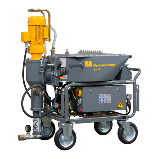
Summary of Contents for Putzmeister MP 25
- Page 1 Operating Instructions for the machine operator and maintenance personnel always keep by the machine Translation of the original instructions Mixer pump MP 25 Machine no. 4-0124 365524000_en...
- Page 2 The QR code takes you to the directory in which the spare parts lists are stored. The digital spare parts list therefore replaces the previous printed version. Putzmeister Mörtelmaschinen GmbH Max-Eyth-Straße 10, 72631 Aichtal, Germany Tel.+49 (0) 7127 599-0 Fax +49 (0) 7127 599-743...
-
Page 3: Table Of Contents
Table of contents Table of contents Guide to the Operating Instructions ........1 — 1 Foreword ......................... 1 — 2 Icons and symbols ......................1 — 3 1.2.1 Layout of warning notices ....................1 — 4 Safety regulations ..............2 — 1 Definition of terms ...................... - Page 4 Table of contents 2.6.2 Qualified personnel ......................2 — 10 2.6.3 Subject expert ......................... 2 — 10 Sources of danger ......................2 — 10 2.7.1 General sources of danger ....................2 — 10 2.7.2 Danger from hot machine components ................2 —...
- Page 5 Table of contents Safety equipment ......................3 — 7 3.6.1 Protective grille ........................ 3 — 7 3.6.2 EMERGENCY STOP button (option) ................3 — 8 3.6.3 Tilt switch ........................3 — 10 Description of the functions ..................... 3 — 10 Control devices .......................
- Page 6 Table of contents Electrical connection ....................... 4 — 18 4.9.1 Power sources ........................ 4 — 19 4.9.2 Electrical supply cables ....................4 — 20 4.9.3 Connecting the machine ....................4 — 21 Starting up ................5 — 1 Setting up the machine for initial commissioning ............5 —...
- Page 7 Table of contents Pumping operations ......................6 — 14 6.7.1 Breaks in pumping ......................6 — 15 6.7.2 Terminating pumping operations ..................6 — 16 Blockages ........................6 — 17 6.8.1 Removing blockages ....................... 6 — 18 Cleaning .......................... 6 — 20 6.9.1 General ...........................
- Page 8 Table of contents 8.6.7 Adjusting the auger pump ....................8 — 20 8.6.8 Adjusting the air valve fitting pressure switch ..............8 — 24 8.6.9 Adjusting the water valve fitting pressure switch ............. 8 — 25 Decommissioning ..............9 — 1 Temporary decommissioning ..................
- Page 9 In this chapter you will find notes and information that will help you use these Operating Instructions. If you have any queries, please contact us in confidence at: Putzmeister Mortar Machines GmbH Max-Eyth-Straße 10 72631 Aichtal, Germany Tel.: +49 (0)7127 599-0 Fax: +49 (0)7127 599-743 E-mail: mm@putzmeister.com...
-
Page 10: Guide To The Operating Instructions
Guide to the Operating Instructions Foreword These Operating Instructions aim to help you to familiarise yourself with the machine and make use of its possible applications as desig‐ nated. The Operating Instructions contain important information on how to operate the machine safely, properly and economically. Observing these instructions helps to avoid danger, to reduce repair costs and downtimes and to increase the reliability and service life of the ma‐... -
Page 11: Icons And Symbols
The pages are divided into chapters, where they are numbered con‐ secutively. Example: 3 – 2 (chapter 3 – page 2) © Putzmeister Mörtelmaschinen GmbH Icons and symbols The following icons and symbols are used: Icon/symbol/ Meaning designation ▶... -
Page 12: Layout Of Warning Notices
Guide to the Operating Instructions Icon/symbol/ Meaning designation Special tools are required. This icon is followed by a list of special tools that are required to carry out the task. (Normal tools, i.e. conventional tools or tools carried in the vehicle, are not listed spe‐ cially.) This icon is followed by an indication of required maintenance work. - Page 13 Guide to the Operating Instructions WARNING Indicates a dangerous situation in which an accident resulting in se‐ rious or fatal injuries may occur. ▶ After identifying the risk, instructions are set out which are inten‐ ded to avoid or remedy the risk. CAUTION There is a risk of injury to the entire body, however there is no risk of serious or fatal injuries.
- Page 14 1 — 6...
- Page 15 Safety regulations This chapter summarises the most important safety regulations. This chapter must be read and understood by all persons who come into contact with the machine. The various regulations also appear again at the appropriate points in the Operating Instructions. Special safety regulations may be necessary for some tasks.
-
Page 16: Safety Regulations
Safety regulations Definition of terms The following sections explain the terms used in these Operating In‐ structions and describe the requirements for specific groups of per‐ sonnel. 2.1.1 Mixing pump The mixing pump is a machine designed for processing premixed dry mortar. -
Page 17: Service Technician
Safety regulations 2.1.7 Service technician Personnel qualified or authorised by the manufacturer to perform maintenance tasks. 2.1.8 Maintenance Maintenance includes all measures required to inspect and repair a machine. 2.1.9 Workplace The workplace is the area in which people must remain in order to carry out the work. -
Page 18: Designated Use
Safety regulations Observe the following basic principles: ● Safety equipment must not be removed, decommissioned or other‐ wise modified. ● Safety equipment removed for maintenance work must be fitted again as soon as work is complete. ● Following assembly, the safety equipment must be checked to en‐ sure it is fully functional. -
Page 19: Improper Use
Safety regulations The maximum delivery pressure must not exceed that specified on the rating plate or in the technical data. The machine is filled via the hopper. All protective covering elements of the machine must be fitted during operation. The machine must be operated only with the safety equip‐ ment fitted. -
Page 20: Removal Or Modification Of Safety Equipment
Safety regulations 2.4.2 Removal or modification of safety equipment Depending on the model, the machine is fitted with different safety equipment for protection against serious personal injury. Removing, modifying or decommissioning safety equipment is pro‐ hibited. If safety equipment has been modified, damaged, removed or is not fully functional, the machine must be shut down and secured immedi‐... -
Page 21: Transport
Safety regulations 2.4.7 Transport The machine may only be transported as stated. During transport, lift‐ ing equipment, lifting tackle or other auxiliary devices that are unsuita‐ ble or not reliable and safe in operation must not be used. Loading the machine with unauthorised materials and accessories, as well as exceeding the maximum permissible gross weight of the machine, is prohibited. -
Page 22: Changing The Works Settings
Safety regulations 2.4.10 Changing the works settings The works settings must not be changed. A few examples are listed below: ● Pressure and performance settings ● Software versions and software parameters 2.4.11 Structural changes Structural changes must not be implemented without permission from the manufacturer. -
Page 23: Exclusion Of Liability
Safety regulations The safety and accident prevention regulations from the following in‐ stitutions must be observed: ● The legal authority of the country of use ● The Industrial Employers’ Liability Insurance Associations ● The responsible commercial liability insurance company The legal authority places liability for accidents caused by not observ‐ ing safety and accident prevention regulations or by lack of care with the operating personnel or (where they cannot be held responsible due to lack of training or basic knowledge) the supervisory personnel. -
Page 24: Qualified Personnel
Safety regulations The following personnel must only work on the machine under the permanent supervision of an experienced person: ● Personnel participating in training courses ● Trainees ● Personnel being instructed ● Personnel receiving general training 2.6.2 Qualified personnel Personnel who have successfully completed a specialist training course that qualifies them to carry out specific activities. -
Page 25: Danger From The Delivery Line And Coupling System
Safety regulations 2.7.3 Danger from the delivery line and coupling system The delivery line and coupling system is designed for a maximum op‐ erating pressure of 40 bar. The maximum operating pressure must not exceed 40 bar. Safety equipment Never remove or modify safety equipment on the machine. If safety equipment needs to be removed for set-up, maintenance or repairs, the safety equipment must be refitted and checked immedi‐... - Page 26 Safety regulations Symbol Meaning Safety helmet The safety helmet protects your head, e.g. against falling concrete or parts of the deliv‐ ery line if the lines burst. (DIN EN 397:2022; Industrial safety helmets) Safety footwear Safety footwear protects your feet against fall‐ ing objects and against penetration by projec‐...
-
Page 27: Risk Of Injury, Residual Risks
Safety regulations Symbol Meaning Safety harness When working at heights, use climbing aids and platforms that are intended for this pur‐ pose and comply with the safety regulations or wear a safety harness. Relevant national regulations must be observed. (DIN EN 361:2002; Personal protective equip‐ ment against falls from a height - Full body harnesses;... -
Page 28: Risk Of Crushing And Impact
Safety regulations ● Injuries to the skin and eyes caused by dust particles, concrete spatter, water glass or other chemical substances. ● Damage to health caused by breathing in dust particles or cleaning agents, solvents and preservatives. ● Injuries caused by opening pressurised delivery lines (e.g. follow‐ ing blockages). -
Page 29: Assembly Of The Auger Pump
Safety regulations WARNING Risk of crushing due to lifting and loading the machine ▶ Lift the machine carefully with a forklift truck and move it with great care. ▶ When lifting with the crane, determine the centre of gravity of the machine by lifting it carefully. -
Page 30: Electrical Contact
Safety regulations Figure 1: Risk of crushing in the end stop area of the auger pump 2.12 Electrical contact There is a risk of death from electrical contact on the control cabinet, the electrical lines and the engine during the following operating modes: ●... -
Page 31: Conduct In An Emergency
Safety regulations DANGER Risk of death due to the incorrect removal of a blockage When removing a blockage with compressed air, the delivery line may burst or the blockage may be ejected from the delivery line at a high pressure. ▶... -
Page 32: Noise Emissions
Safety regulations Make sure that you dispose of empty functional fluid containers, old filters, batteries, replacement parts, used cleaning rags, etc. in line with regulations and in an environmentally friendly manner. Only work with waste disposal companies who are approved by the responsible authorities. -
Page 33: Safety-Related Parts (Srps)
Safety regulations 2.17 Safety-related parts (SRPs) WARNING Risk of death Incorrect assembly of safety-related parts can result in malfunc‐ tions. ▶ Safety-related parts (SRP) should only ever be repaired, main‐ tained or replaced by qualified personnel with the necessary au‐ thorization. -
Page 34: Spare Parts
SRP service life in years 10 = 10 years Hourglass – SRP service life Example spare parts sheet “EB00-5-xxxxx-xxxx” (3) for every safety-related part Putzmeister specifies a service life (SRP). The SRPs must be replaced once this service life has elapsed. 2.18 Spare parts Spare parts must meet the technical requirements specified by the manufacturer. -
Page 35: Storing The Machine
Safety regulations Accessories not included in the products supplied with the ma‐ chine are supplied by the manufacturer and can be purchased via the Parts Sales department. The supplied accessories are listed on the delivery note. The operating company is responsible for ensuring that the correct accessories are used. - Page 36 2 — 22...
-
Page 37: General Technical Description
General technical description This chapter describes the components and assemblies on this ma‐ chine and describes how they function. Please note that possible (op‐ tional) auxiliary equipment is also described. 3 — 1... -
Page 38: Machine Model
General technical description Machine model Your machine is an MP 25. The following data can be found on the rating plate: ● Machine model ● Machine number You will make it much easier for us to respond to any questions or orders if you give us the details of the machine model and the ma‐... -
Page 39: Technical Data
Carrying handles (4x) Compressor Fork-lift truck pocket Screw-in aid Water filter Water pump Foot brake Technical data The following technical data and characteristics relate to the MP 25. Dimensions Length 1344 mm Width 728 mm Height 1484 mm Filling height... - Page 40 General technical description Perform‐ MP 25 MP 25 MP 25 MP 25 ance data 111417500 111417510 111417530 111417420 Drive mo‐ Electric motor: Electric Electric 5.5 kW/400 V/50 Hz/ motor: motor: 5.5 385 rpm 5.5 kW/400 kW/220 V/ V/60 Hz/ 60 Hz/...
- Page 41 General technical description Perform‐ MP 25 MP 25 MP 25 MP 25 ance data 111417500 111417510 111417530 111417420 Inclination Max. 10° angle in transverse direction Control 48 V 42 V voltage Power con‐ CEE device connector, 5 x 4 mm² 32 CEE de‐...
-
Page 42: Rating Plate
General technical description Rating plate The most important machine specifications are shown on the rating plate. Figure 5: Rating plate Item Designation CE marking (product complies with European regulations) EAC marking (product complies with the technical regulations of the Eurasian Economic Union) Model (machine model) Machine no. -
Page 43: Sound Power Level
General technical description Sound power level Next to the rating plate on the machine there is the plate shown in the picture below, which gives the machine's sound power level measure‐ ment. Figure 6: Plate – sound power level Item Designation Sound power level Value in decibels... - Page 44 General technical description The mesh size of the protective grille is such that material can fall un‐ obstructed into the container, yet it guarantees protection for the ma‐ chine operator. DANGER Risk of death due to removed protective grille Amputations resulting from the crushing, shearing, entanglement or drawing of limbs into the rotating mixing apparatus.
- Page 45 General technical description WARNING Danger to persons from the machine ▶ If situations arise during operation which could endanger per‐ sons, the machine must be stopped immediately by pressing the EMERGENCY STOP button. ▶ After an EMERGENCY STOP, eliminate the danger before re‐ starting the machine.
-
Page 46: Description Of The Functions
General technical description If your machine is not equipped with an EMERGENCY STOP but‐ ton, switch the machine off at the main switch when an impending danger arises. Switching the machine off at the main switch cau‐ ses an EMERGENCY STOP. 3.6.3 Tilt switch The machine is fitted with a tilt switch. -
Page 47: Control Devices
General technical description Control devices This section provides a summary of the different control devices on the machine. Figure 8: Control devices (different models available) Item Designation Control cabinet Water valve fitting Water pump Compressor Air valve fitting (hidden) Spray gun The data refers to the series machines. -
Page 48: General
General technical description 3.9.1 General DANGER Risk of death due to fatal electric shock ▶ Work on the electrical system may only be carried out by certi‐ fied, licensed and qualified electricians (proof of qualification in line with EN 60204, part 1, page 14, item 2.21). NOTICE Machine damage caused by incorrect fuses Overriding fuses or fuses that are too strong may destroy the elec‐... -
Page 49: Overview
General technical description 3.9.2 Overview Figure 9: Control cabinet Item Designation CEE device socket Power supply connection CEE device socket Compressor connection Main switch Power supply ON - OFF Double pushbutton Pump ON – OFF Illuminated push-button Yellow indicator lamp: Incorrect direction of rotation Push-button: Reverse pump Selector switch Mix –... - Page 50 General technical description Item Designation Multiple socket outlet Pump connection Multiple socket outlet Agitator connection Selector switch Water pump (different function depending on connection) EMERGENCY STOP button (dependent on model) Switching off the machine in an emergency Figure 10: Symbols on the control cabinet Item Designation Compressor connection...
- Page 51 General technical description 3.9.2.1 “Mixing and pumping” selector switch Figure 11: “"Mix – OFF – Mixing and pumping"” selector switch The selector switch can be used to determine whether the pump and/or the agitator should stop during breaks in pumping, for in‐ stance.
-
Page 52: Compressor
General technical description Water pump OFF – Automatic selector switch Switch position Result Left: “OFF” Water pump off Right: “Automatic” The water pump starts. The mix‐ ing pump starts after 2 seconds. They stop synchronously. 3.10 Compressor A compressor can be integrated to generate the air required to spray the material, depending on the model. -
Page 53: Auger Pump
General technical description WARNING Risk of injury due to damage to the compressor ▶ Do not use the device if there is visible damage or if the com‐ pressor is producing unusual sounds or vibrations. ▶ Only qualified personnel may carry out work on the compressor. 3.11 Auger pump The auger pump fitted in the machine is a so-called displacement... - Page 54 General technical description Figure 15: Auger pump with clamping sheath overview Item Designation Screw conveyor Screw conveyor barrel Clamping sheath Clamping bolts The wear of the auger pump can be compensated by tightening. You can also adjust the delivery pressure by pre-tightening or relieving the tension on the screw conveyor barrel.
-
Page 55: Air Valve Fitting
General technical description 3.12 Air valve fitting Item Designation Pressure switch Pressure gauge “Control cabinet connection” connector plug Hose coupling for air tapping Air is channelled from the compressor into the air valve fitting for spray gun operation. The air valves and the air hose connection are located here. -
Page 56: Water Filter
General technical description Item Designation Water pump Water filter Water pump water connection Connection – water removal Ball valve – water removal Water pump outlet The electrically driven water pump is used as a pressure booster pump in case the pressure in the water network is not sufficient. The water pump is a suction pump that draws the water in itself. -
Page 57: Water Valve Fitting
General technical description 3.14 Water valve fitting Item Designation Water connection Pressure switch Pressure gauge Pressure reducer Drain cock Valve Drain cock Flow meter Mixing pipe connection Control valve for water volume The water valve fitting conveys the water to the mixing pipe. The wa‐ ter volume is adjusted at the control valve. -
Page 58: Spray Gun
General technical description 3.15 Spray gun The spray gun is attached to the end of the delivery line. Figure 16: Spray gun overview Item Designation Rubber fine plaster nozzle Delivery line connection Material lever (dependent on model) Remote control valve Air supply coupling Stop cock (dependent on model) Air-regulation cock (dependent on model) -
Page 59: Cable Remote Control
General technical description 3.16 Cable remote control A cable remote control is available as an option. The socket for this is located on the control cabinet. Figure 17: Cable remote control Item Designation “ON – OFF” toggle switch “Remote control” connector plug 3.17 Injection hood The injection hood is not included in the products supplied with the... -
Page 60: Compact Filter
General technical description Figure 18: Injection hood (different models available) Item Designation Fill-level sensor Compact filter Control cable An injection hood equipped with a compact filter and a fill-level sensor is placed on the mortar machine. A delivery line connects the injection hood to the delivery container on the silo/container. -
Page 61: Options
3.18 Options Consult your dealer or local Putzmeister Mortar Machines GmbH rep‐ resentative as to how and whether you should upgrade your machine. You can find further options and accessories in the Putzmeister Mortar Machines GmbH catalogue or online at: www.putzmeis‐... - Page 62 3 — 26...
- Page 63 Transport, setting up and connection In this chapter you will find information concerning safe transport of the machine. In this chapter, you will furthermore find information on the other tasks necessary for the assembly and connection of the ma‐ chine. Starting up the machine is described in the “Starting up” chap‐ (Starting up P.
-
Page 64: Transport, Setting Up And Connection
Transport, setting up and connection Unpacking the machine The machine is packaged for transport at the works. The packaging is made from recyclable material. Dispose of the packing material in compliance with the nationally valid environmental protection regulations. Transporting the machine WARNING Risk of crushing due to lifting and loading the machine ▶... -
Page 65: Loading Using A Fork-Lift Truck
Transport, setting up and connection 4.2.1 Loading using a fork-lift truck Figure 19: Fork-lift truck pocket Use the fork-lift truck pocket on the cross strut at the bottom of the frame to load the machine with a suitable fork-lift truck. This is the on‐ ly way to ensure that the machine cannot fall while being transported with a fork-lift truck. - Page 66 Transport, setting up and connection Item Designation Lifting eye 4.2.2.1 Loading the individual components The machine can be dismantled into its individual components by two (Dismantling the machine into individual components people P. 4 — 6) . To transport the individual components with a suitable crane, proceed as follows: 1.
- Page 67 Transport, setting up and connection Item Designation Lifting belt Pump support bracket 4. Hang the mixing pump from its support bracket using a lifting belt. 5. Raise the load. Item Designation Lifting belts Reservoir 6. Secure the lifting belts at the four carrying handles. 7.
-
Page 68: Dismantling The Machine Into Individual Components
Transport, setting up and connection Dismantling the machine into individual compo‐ nents For transport in small spaces, on small truck beds, in stairwells, etc., the mixing pump can be dismantled without using tools. The machine can be dismantled into its individual components and transported by two people. - Page 69 Transport, setting up and connection Figure 21: Foot brake 1. Press the foot brake Figure 22: Venting hose 2. Disconnect the venting hose from the reservoir. 3. Disconnect the electric cable for the mixing pump motor from the control cabinet. 4 —...
- Page 70 Transport, setting up and connection Item Designation Water hose Mixing pipe 4. Disconnect the water hose from the mixing pipe. Item Designation Ring nut Material gate valve 5. Close the material gate valve. 6. Loosen the ring nut. 4 — 8...
- Page 71 Transport, setting up and connection Item Designation Release lever 7. Hold the mixing pump securely using the handle on the drive mo‐ tor. 8. Push the release lever downwards. ⇒ The mixing pump can now be swivelled in its bracket. Item Designation Mixing pump...
- Page 72 Transport, setting up and connection 12. Pull out the connector for the agitator motor on the control cabi‐ net. Item Designation Sealing pin Toolbox Base frame Reservoir 13. Unlock the reservoir by pulling out the sealing pin (in the toolbox). 14.
-
Page 73: Assembling The Disassembled Machine
Transport, setting up and connection Assembling the disassembled machine After transporting the individual components, proceed as follows to reassemble the machine. Figure 23: Individual components (different models available) Item Designation Reservoir Angle bracket Angle retainer Base frame 1. Place the reservoir on the base frame. 2. - Page 74 Transport, setting up and connection Item Designation Sealing pin 3. Secure the container using the sealing pin (in the toolbox). 4. Insert the connector for the agitator motor on the control cabinet. Item Designation Mixing pump 5. Raise the mixing pump into the mixing pump bracket from above. 6.
- Page 75 Transport, setting up and connection Item Designation Release lever 7. Pull the release lever upwards. Item Designation Ring nut 8. Screw in the ring nut. ⇒ The mixing pump is now locked in its bracket. 9. Connect the electric cable for the mixing pump motor in the con‐ trol cabinet.
- Page 76 Transport, setting up and connection Item Designation Venting hose Reservoir 10. Connect the venting hose for the mixing pump to the reservoir. 11. Position the compressor in the base frame and connect the cable to the control cabinet. Item Designation Water hose Mixing pipe 12.
-
Page 77: Selecting A Setup Site
Transport, setting up and connection Selecting a setup site As a rule, the site management determines the set-up site for the ma‐ chine and prepares the site accordingly. The responsibility for setting up the machine safely falls on the ma‐ chine operator. -
Page 78: Mounting The Injection Hood
Transport, setting up and connection 2. Press the foot brake down fully in order to prevent the machine rolling inadvertently. NOTICE Risk of machine damage due to inclination angle that is too large The full functionality of the machine is no longer ensured for larger inclination angles. -
Page 79: Water Connection
Transport, setting up and connection Figure 24: Injection hood Item Designation Clamping bolt Locking pin Sensor Locking tensioner Reservoir 2. Insert the injection hood with the locking pin on the reservoir and secure it using the clamping bolts. 3. Attach the injection hood to the reservoir using the locking ten‐ sioner. -
Page 80: Electrical Connection
Transport, setting up and connection Please ensure that you check the requirements for connection to the water supply before beginning connection work: ● The line must be at least 3/4" in diameter. ● The available water pressure must be at least 4 bar. Item Designation Water connection... -
Page 81: Power Sources
Transport, setting up and connection ● The local laws and regulations must be observed. ● Protection in the case of indirect contact must be ensured through the automatic cut-out of the supply in line with IEC 60364-4-41:2005. DANGER Risk of death due to fatal electric shock ▶... -
Page 82: Electrical Supply Cables
Transport, setting up and connection The power source must fulfil the following criteria: ● The power source is equipped with a residual current device (RCD). ● The connected load of the existing electrical installation must be sufficient for the machine. Please refer to the technical data for the maximum pre-fuse. -
Page 83: Connecting The Machine
Transport, setting up and connection 4.9.3 Connecting the machine DANGER Risk of death from switching on the main switch too soon ▶ The main switch must remain secured while the machine is set ▶ Only switch on the main switch once the machine has been completely and correctly set up. - Page 84 4 — 22...
- Page 85 Starting up This chapter contains information on starting up the machine. It de‐ scribes the work steps required for the initial commissioning of the machine and how to prepare the machine before use after longer breaks. There is also a description on how to check the condition of your machine and how to carry out a test run with function checks.
-
Page 86: Starting Up
Starting up Setting up the machine for initial commissioning To save space when transporting the machine, the auger pump is not mounted for delivery from the works. After unpacking the machine, you must mount the auger pump for initial commissioning. 5.1.1 Mounting the auger pump The screw conveyor must first be mounted in the screw conveyor bar‐... -
Page 87: Mounting The Auger Pump On The Mixing Pipe
Starting up 5.1.1.1 Screw-in aid A screw-in aid for the screw conveyor parts is permanently welded to the frame. The screw-in aid retainer keeps the screw conveyor barrel securely in position so that the screw conveyor can be screwed into the screw conveyor barrel with both hands. - Page 88 Starting up Item Designation Turnbuckle WARNING Risk of crushing ▶ When opening the mixer motor, do not reach into moving com‐ ponents. 1. Open the turnbuckle to open the mixer motor. 2. Open the mixer motor sideways. Item Designation Mixer shaft Mixing pipe 3.
-
Page 89: Mounting The Mixing Pump
Starting up 5.1.3 Mounting the mixing pump Item Designation Auger pump Pressure flange Mixing pipe Threaded sleeve Auger pump pressure connection unit 1. Insert the auger pump in the pressure flange. 2. Hang the auger pump pressure connection unit on the mixing pipe flange using the threaded sleeves. -
Page 90: Checks
Starting up WARNING Risk of crushing due to turning of the auger pump Depending on the mounting position of the stator or screw conveyor barrel, it can turn all the way to the stop when the machine is switched on. ▶... -
Page 91: Visual Checks
Starting up 5.2.1 Visual checks Some visual checks should be carried out before starting up the ma‐ chine. 1. Always check the machine thoroughly for defects before the start of work. 2. Check the delivery line for damage. 3. Check whether all safety equipment is fitted and fully functional. 4. -
Page 92: Checking The Direction Of Rotation Of The Motor
Starting up 2. Check whether the machine is connected to a suitable water sup‐ (Water connection P. 4 — 17) ply (at least 4 bar). (Electrical 3. Check whether the required power supply is available. connection P. 4 — 18) For the test run, you must first switch on the main switch and then the pump. - Page 93 Starting up 5.3.3 Changing the direction of rotation Figure 26: Changing the direction of rotation Item Designation Main switch Slide for changing the direction of rotation 1. Switch off the main switch (position “0”). 2. Move the slide for changing the direction of rotation. ⇒...
-
Page 94: Starting The Motor
Starting up 5.3.4 Starting the motor The motor is switched on using the double push-button. Item Designation “Power supply ON – OFF” main switch “Pump ON – OFF” double push-button “"Mix – OFF – Mixing and pumping"” selector switch 1. Switch the machine on at the main switch. ⇒... -
Page 95: Checking The Emergency Stop Button
Starting up WARNING Risk of injury due to defective safety equipment Defective safety equipment may appear safe even though it is not. This can lead to the machine continuing to run or not switching off quickly enough in the event of an impending danger. ▶... - Page 96 Starting up WARNING Risk of injury due to defective EMERGENCY STOP button The machine is no longer safe to operate if the EMERGENCY STOP button is defective, as you will no longer be able to switch off the machine quickly enough in the event of danger. ▶...
-
Page 97: Function Check Of The Tilt Switch
Starting up 5.4.3 Function check of the tilt switch Your machine is fitted with a tilt switch. Check the function of the tilt switch by proceeding as follows. Item Designation Turnbuckle ( Starting the motor P. 5 — 10) 1. Start the drive motor. 2. - Page 98 Starting up 2. Switch the machine off at the main switch. 3. Secure the machine against unauthorised starting or use. 5 — 14...
- Page 99 Operation This chapter contains information on operating the machine. It ex‐ plains the work steps required for setting, operation and cleaning. 6 — 1...
-
Page 100: Operation
Operation Requirements You must have completed the operations for setting up and starting up the machine before you begin operating the machine. Before you fill the machine with material and start pumping it through the delivery line, you must make sure that: ●... -
Page 101: Starting To Pump
Operation Familiarise yourself with the position of the EMERGENCY STOP button(s) on your machine. 1. In the event of impending danger, press the EMERGENCY STOP button ⇒ The pump stops. ⇒ The motor is switched off. ⇒ All control panels and switch boxes are electrically locked. 2. -
Page 102: Adding Dry Mortar
Operation Item Designation “Water flow” push-button ▶ Press the “Water flow” push-button until the water level reaches 1.5 cm above the screw conveyor barrel. The water should not reach any higher than 1.5 cm above the screw conveyor barrel. If the water level exceeds this height, pump the water out. -
Page 103: Start-Up Water Value
Operation The compressor may only be operated using the pressure switch. Item Designation “Pump ON – OFF” double push-button “"Mix – OFF – Mixing and pumping"” selector switch “Water pump” selector switch 3. Turn the “Mixing – OFF – Mixing and pumping” selector switch clockwise to “Mixing and pumping”... - Page 104 Operation Item Designation Control valve for water volume Flow meter You can adjust the water volume by turning the volume control valve. This is done by gradually adjusting the water volume in small steps (20–40 l/h). This can be seen by looking at the float through the in‐ spection glass.
-
Page 105: Connecting The Delivery Line
Operation Item Designation Pressure connection 2. Inspect the mortar consistency at the pressure connection. 3. Gradually decrease the water value using the volume control valve until you reach the required mortar consistency. ⇒ Pumping start-up is finished when the required mortar consis‐ tency exits at the pressure connection. -
Page 106: Starting To Pump With Lime Grout
Operation 6.4.1 Starting to pump with lime grout The entire delivery line must be wetted at the start of pumping opera‐ tions. The lime grout must generally be used when starting to pump. The grout lubricates the inside of the delivery line and prevents block‐ ages. -
Page 107: Using The Spray Gun
Operation Item Designation Pressure connection Coupling Delivery line 2. Connect the filled side of the delivery line to the pressure connec‐ tion. 3. Pump the grout through the delivery line. 4. Collect the grout in a suitable container at the end of the delivery line and dispose of it according to regulations. - Page 108 Operation WARNING Risk of injury due to material spraying out of the spray gun ▶ Close the remote control valve on the spray gun before switch‐ ing on the machine. ▶ The spray gun operator must always wear protective goggles during the spraying process.
-
Page 109: Adjusting The Air Nozzle Tube
Operation 6.5.1 Adjusting the air nozzle tube Figure 29: Different models available Item Designation Air nozzle tube Mortar nozzle ▶ Depending on the mortar consistency, use nozzle inserts measur‐ ing 10, 12 or 14 mm – these are referred to as fine plaster noz‐ zles. - Page 110 Operation 2. Connect the air hose to the air valve fitting and the spray gun. 3. Close the remote control valve on the spray gun. 4. Depending on the model, you may also need to close the stop cock or the air-regulation cock. Opening or closing the remote control valve on the spray gun switches the pump on and off.
- Page 111 Operation 4. If necessary, turn the volume control valve for the water volume on the water valve fitting in order to achieve the required mortar consistency. This changes the volumetric flow rates. You can read off the volumetric flow rate on the flow meter. The container must never be pumped completely empty as this will cause the pump to suck in air.
-
Page 112: Working With The Cable Remote Control
Operation Working with the cable remote control To use the cable remote control, proceed as follows: Figure 31: Cable remote control Item Designation “ON – OFF” toggle switch “Remote control” connector plug 1. Pull the bridge plug or the connector plug for the pressure switch out of the “Remote control connection”... - Page 113 Operation Make sure you are completely familiar with the procedure for shut‐ ting down the machine in an emergency situation before you start pumping. If a malfunction occurs during the pumping process, consult the “Faults, cause and remedy” chapter first. Contact the manufactur‐ er's After Sales department for advice if you are unable to rectify the fault yourself.
- Page 114 Operation 3. During short breaks in pumping, dump the delivery line pressure by brief reverse pumping. 4. Switch off and clean the machine in the event of longer breaks. 6.7.2 Terminating pumping operations In the event of an interruption in work that lasts ●...
- Page 115 Operation Item Designation Pressure gauge Pressure flange WARNING Risk of injury due to the conveyed material spraying out ▶ Secure the danger zone to prevent unauthorised access. ▶ Wear protective goggles. ▶ Always wear personal protective equipment. ▶ You should only uncouple the delivery line once you have checked the pressure gauge to see that the system is fully dep‐...
- Page 116 Operation Blockages increase the risk of accidents. A well-cleaned and leak- tight delivery line prevents the formation of a blockage. Blockages have the following causes: ● Insufficient lubrication of the delivery line. ● Hard to pump or slightly segregating conveyed material. ●...
- Page 117 Operation Item Designation “Power supply ON – OFF” main switch “Pump ON – OFF” double push-button “Reverse pump” illuminated push-button “"Mix – OFF – Mixing and pumping"” selector switch In order to remove a blockage, depressurizing must first be car‐ ried out by briefly pumping in reverse.
- Page 118 Operation WARNING Risk of injury due to the conveyed material spraying out ▶ Secure the danger zone to prevent unauthorised access. ▶ Wear protective goggles. ▶ Always wear personal protective equipment. ▶ You should only uncouple the delivery line once you have checked the pressure gauge to see that the system is fully dep‐...
- Page 119 Operation NOTICE Machine damage caused by water penetration ▶ Prior to cleaning the machine with water or a steam jet/high- pressure cleaner or other cleaning agents, cover or seal all openings which water, steam or cleaning agents must not pene‐ trate for safety or operating reasons.
- Page 120 Operation ● Never use sea water or other water containing salt for cleaning purposes. ● Rinse the machine immediately with clean water if it comes into contact with sea water. ● Completely remove all covers/tape after cleaning. 6.9.2 Cleaning the machine Clean the machine first, then the delivery line.
- Page 121 Operation Item Designation Turnbuckle 5. Open the mixer motor sideways. WARNING Risk of injury due to moving components ▶ When opening the mixer motor, do not reach into moving com‐ ponents. 6. Pull the mixing spiral out of the machine. 7.
- Page 122 Operation 12. Repeat the process until clean water exits at the pressure con‐ nection. ⇒ The machine is now fully cleaned out. 13. Switch the machine off at the main switch. 14. Open the turnbuckle to open the mixer motor. 15.
- Page 123 Turn your face away when opening the line coupling. ▶ Open the coupling carefully. 1. Release the delivery line at the pressure connection. 2. Soak a Putzmeister sponge ball in water. Figure 33: Cleaning the delivery line Item Designation Sponge ball Delivery line 3.
- Page 124 Operation 6.9.3.1 Cleaning the delivery line using water pressure The delivery line is cleaned by water pressure. Use the water connec‐ tion piece included in the accessory package for this purpose. Figure 34: Water connection piece Item Designation Water connection piece Delivery line 1.
- Page 125 Operation If your machine has a water pump, switch on the water pump using the “Water pump” selector switch. The water pump must not run if deadheading has occurred (no water removal). 4. Use the water pressure to push the leavings and sponge ball out of the delivery line.
- Page 126 Operation Figure 35: Cleaning seals Item Designation Pressure connection Rubber seal 1. Clean all seals and seal seats. 2. Grease the seals before replacing them. 3. If there is a risk of freezing, drain the machine and lines fully of residual water.
- Page 127 Operation 6.9.5 Cleaning the spray gun Item Designation Air valve Air nozzle tube Nozzle cleaner 1. Clean the air cock and air nozzle tube on the spray gun. 2. Clean the air nozzle tube using the nozzle cleaner. 6 — 29...
- Page 128 6 — 30...
- Page 129 Faults, cause and remedy This chapter gives you an overview of faults and their possible cau‐ ses, and also ways in which you may rectify them. Observe the safety regulations when troubleshooting. Inspection and maintenance personnel must have authorisation and the necessary technical qualification.
- Page 130 Faults, cause and remedy General machine The following section provides a description of possible causes of faults and their remedies. Fault Cause Correction Machine does not start despite power Water pressure too low. Pressure Remove and clean the dirt trap located and water connections.
- Page 131 Faults, cause and remedy Fault Cause Correction Blockage in the delivery line and shut‐ The pump should be carefully started down of the pump due to the overpres‐ up initially before any material is actual‐ (Starting to pump sure device tripping. ly pumped.
- Page 132 Faults, cause and remedy DANGER Risk of death due to fatal electric shock ▶ Work on the electrical systems and equipment of the machine must only be carried out by a qualified electrician or by instruc‐ ted persons under the supervision and guidance of a qualified electrician and in accordance with electrical engineering rules and regulations.
- Page 133 Maintenance In this chapter you will find information on maintenance work which is necessary for the safe and efficient operation of the machine. We would like to explicitly emphasise here that all prescribed checks, inspections and preventative maintenance work must be conscien‐ tiously carried out.
- Page 134 Maintenance Maintenance and inspection by the machine oper‐ ator Regular preventative inspections allow you to detect machine dam‐ age well in advance and implement the necessary repair measures. See the “Maintenance intervals” section for information on the type and frequency of necessary inspection work. It is recommended that the details and results of the inspections are documented in a suitable format.
-
Page 135: Adjusting The Auger Pump
Maintenance Frequency/interval Action Comments daily visual Check warning notices and plates. Replace immediately if damaged or missing. Visual inspection of electric cabling weekly Water filter check Replace water filter as required every 2 weeks Clean the dirt trap screen in the pressure re‐ See the Maintenance work (Cleaning the dirt trap ducer valve... - Page 136 Maintenance Residual risks during maintenance work Maintenance work may present a risk of personnel or third parties suffering injury or death. 8.3.1 Personnel requirements Only qualified personnel may carry out maintenance work. Qualified personnel must have successfully completed a specialist training course that qualifies them to carry out such activities.
- Page 137 Maintenance WARNING Risk of injury due to the machine starting unexpectedly ▶ Before performing any maintenance work, shut down the ma‐ chine and secure it to prevent accidental startup (e.g. by locking control equipment). If this is not possible, enlist the help of a second person to prevent the machine from starting unexpect‐...
- Page 138 Maintenance NOTICE Environmental pollution caused by incorrect disposal of functional fluids ▶ Collect all functional fluids, e.g. used oil, filters and auxiliary ma‐ terials, separately. ▶ Dispose of these in line with the relevant national and regional regulations. ▶ Only work with waste disposal companies who are approved by the responsible authorities.
- Page 139 DIN 51 502: K2K, NLGI Class 2. 8.4.4 Screw conveyor You must only use Putzmeister silicone oil for mounting the screw conveyor. Putzmeister silicone oil is available as a spray can (part number 210923.003). General tightening torques for bolts See the spare parts list for an overview of general tightening torques.
- Page 140 Maintenance 8.6.1 Before beginning maintenance work There are specific risks of accidents associated with maintenance, in‐ spection and repair work. Therefore always read the “Safety regula‐ tions” chapter and the description “Residual risks during maintenance work” in this chapter. Maintenance personnel must have authorisation and the necessa‐ ry technical qualification.
- Page 141 Maintenance Clean the exterior of the device from time to time using a cleaning rag; do not spray the device using steam jet equipment. CAUTION Risk of burning! The device may be very hot after long periods of use. ▶ Allow the compressor to cool.
- Page 142 Maintenance 7. Push the holders back into the covers until you hear the lock but‐ ton engage. 8. You can obtain replacement filter mats from your service dealer. Dispose of used filter elements in line with the applicable environ‐ mental protection regulations. 8.6.3 Cleaning the dirt trap screen in the pressure reducer valve This section describes how to clean the dirt trap screen in the pres‐...
- Page 143 Maintenance 4. Ensure that it is in the correct position and that the O-ring is posi‐ tioned correctly in the screen housing. Replace the O-ring if it is damaged. 5. Screw the screen housing back into the pressure reducer valve and tighten it.
- Page 144 Maintenance 8.6.5 Disassembling the pressure flange This section describes how to disassemble the pressure flange. Ob‐ (Main‐ serve the specifications in the “Maintenance intervals” section. tenance intervals P. 8 — 2) (Mount‐ See also the “Mounting the auger pump on the mixing pipe” ing the auger pump on the mixing pipe P.
- Page 145 Maintenance Item Designation Turnbuckle WARNING Risk of crushing ▶ When opening the mixer motor, do not reach into moving com‐ ponents. 3. Open the turnbuckle to open the mixer motor. 4. Open the mixer motor sideways. Item Designation Mixer shaft Mixing pipe 5.
- Page 146 Maintenance Item Designation Threaded sleeve Auger pump pressure connection unit (1) on the auger pump pres‐ 6. Unscrew the two threaded sleeves (2) using a suitable spanner. sure connection unit Item Designation Mixing pipe Threaded sleeve Auger pump pressure connection unit 7.
- Page 147 Maintenance Item Designation Auger pump Pressure flange 9. Remove the auger pump from the pressure flange. 8.6.6 Mounting the auger pump on the mixing pipe This section describes how to mount the auger pump on the mixing pipe. Observe the specifications in the “Maintenance intervals” sec‐ (Maintenance intervals P.
- Page 148 Maintenance 2. Secure the machine against unauthorised starting. Before mounting the auger pump on the mixing pipe, the mixer shaft must be removed from the mixing pipe. Item Designation Turnbuckle WARNING Risk of crushing ▶ When opening the mixer motor, do not reach into moving com‐ ponents.
- Page 149 Maintenance Item Designation Mixer shaft Mixing pipe 5. Pull the mixer shaft out of the mixing pipe. ⇒ The auger pump can now be mounted. Item Designation Auger pump Pressure flange 6. Insert the auger pump in the pressure flange. 8 —...
- Page 150 Maintenance Item Designation Mixing pipe Threaded sleeve Auger pump pressure connection unit 7. Hang the auger pump pressure connection unit on the mixing pipe flange using the threaded sleeves. Item Designation Threaded sleeve Auger pump pressure connection unit 8. Tighten the two threaded sleeves on the auger pump pressure connection unit securely and evenly on the mixing pipe using a suitable spanner.
- Page 151 Maintenance When tightening the auger pump pressure connection unit, ensure that the sealing surfaces of the auger pump are positioned correct‐ ly on the pressure connection and the mixing pipe. WARNING Risk of crushing due to turning of the auger pump Depending on the mounting position of the stator or screw conveyor barrel, it can turn all the way to the stop when the machine is switched on.
- Page 152 “Maintenance intervals” section. tervals P. 8 — 2) The following special tools are required: ● Putzmeister test pressure gauge, part no. 208745.002 The performance of the auger pump is checked by means of water pressure with the machine running.
- Page 153 Maintenance 8.6.7.1 Inspecting the maintenance-free auger pump Figure 38: Different models available Item Designation Mixing pipe Pressure gauge Pressure connection Delivery line Test pressure gauge Shut-off valve 1. Connect a delivery line that is at least 5 m long to the pressure connection.
- Page 154 Maintenance The indicator on the test pressure gauge decreases to a lower val‐ ue. This value indicates the back-pressure. Repeat the pressure decrease process at least six times. The highest value reached in this process is considered to be valid. 8.6.7.2 Inspecting the auger pump with clamping sheath Figure 39: Different models available...
- Page 155 Maintenance 5. If the shut-off valve is closed and the pressure has reached its peak, read the pressure on the test pressure gauge and switch the machine off. ⇒ The pressure decreases. The indicator on the test pressure gauge decreases to a lower val‐ ue.
-
Page 156: Adjusting The Air Valve Fitting Pressure Switch
Maintenance NOTICE Increased wear on auger parts caused by tensioning the clamping sheath too much ▶ Only pretension the clamping sheath until the required pressure is reached. If the required pressure is not reached even after strong ten‐ sioning: ▶ Remove the auger pump and check it for wear. -
Page 157: Adjusting The Water Valve Fitting Pressure Switch
Maintenance Item Designation Switch-off pressure adjusting screw Pressure differential adjusting screw 1. Remove the housing lid on the pressure switch. (1) , adjust the 2. Using the “Switch-off pressure adjusting screw” switch-off pressure. (+ increasing pressure, - decreasing pres‐ sure) (2) , adjust the 3. - Page 158 Maintenance Figure 41: Water valve fitting pressure switch Item Designation Lower switching value adjusting screw Upper switching value adjusting screw Lower switching value pressure indicator Upper switching value pressure indicator 1. Remove the central screw on the housing lid with a screwdriver. 2.
- Page 159 Decommissioning This chapter contains information on decommissioning the machine. 9 — 1...
-
Page 160: Decommissioning
Decommissioning Temporary decommissioning If the machine is to be shut down temporarily, take the following measures. WARNING Risk of injury due to the conveyed material spraying out ▶ Secure the danger zone to prevent unauthorised access. ▶ Wear protective goggles. ▶... -
Page 161: Final Decommissioning And Disposal
Decommissioning Preserving and lubricating the machine protects it against corro‐ sion and rapid ageing. This is required if the machine: ● Will be shut down for a longer period, ● Is exposed to corrosive atmospheres during storage or trans‐ port. NOTICE Damage to the machine caused by freezing water ▶... -
Page 162: Materials Used
Decommissioning CAUTION Risk of injury due to sharp, exposed components ▶ Always wear personal protective equipment. NOTICE Environmental pollution caused by functional fluids escaping When decommissioning the machine permanently, escaping lubri‐ cants, solvents, preserving agents, etc. may pose a risk. ▶... -
Page 163: Parts Requiring Separate Disposal
Decommissioning Material Used in Steel Compressor parts Air valve fitting parts Plastic, rubber, PVC Gaskets Hoses Cables Wheels Printed circuit boards Polyester Printed circuit boards 9.3.2 Parts requiring separate disposal The following parts and functional fluids must be disposed of sepa‐ rately: Designation Applies for... - Page 164 9 — 6...
- Page 165 Appendix This chapter contains the following topics: ● Lubricant recommendation ● Sample of the EC Declaration of Conformity Depending on the machine model, further documents may be inclu‐ ded in the appendix. 10 — 1...
-
Page 166: Appendix
Lubricant recommendation We have listed all suitable lubricants for your machine in the tables below. Putzmeister accepts no liability for the quality of the lubricants listed or for changes in quality made by the lubricant manufacturers without changing the grade designation. -
Page 167: Sample Ec Declaration Of Conformity
Appendix 10.2 Sample EC Declaration of Conformity The original EC Declaration of Conformity is included in the ma‐ chine's scope of supply. Keep it in a safe place. 10 — 3... - Page 168 10 — 4...
-
Page 169: Index
Index Index In this chapter, you will find the most important keywords and the number(s) of the page(s) on which they appear. This index of key words is in alphabetical order. P. 5 — 6 Checks P. 2 — 20 P. - Page 170 Index P. 2 — 4 P. 8 — 7 Designated use General tightening torques for bolts P. 8 — 12 P. 1 — 1 Disassembling the pressure flange Guide to the Operating Instructions Dismantling the machine into individual components P.
- Page 171 Index P. 5 — 3, P. 6 — 18 Mounting the auger pump on the mixing pipe Removing blockages 8 — 15 P. 8 — 8 Replacing the filter mats P. 4 — 16 Mounting the injection hood P. 8 — 11 Replacing the screw conveyor P.
- Page 172 Index P. 5 — 10 P. 3 — 15 Starting the motor “Water pump” selector switch P. 6 — 3 P. 3 — 19 Starting to pump Water pump P. 6 — 8 P. 3 — 21 Starting to pump with lime grout Water valve fitting P.
Need help?
Do you have a question about the MP 25 and is the answer not in the manual?
Questions and answers