Table of Contents
Advertisement
Quick Links
Advertisement
Table of Contents

Related Manuals for Cybertronix Sentinel EFI-MFZ-50


Summary of Contents for Cybertronix Sentinel EFI-MFZ-50
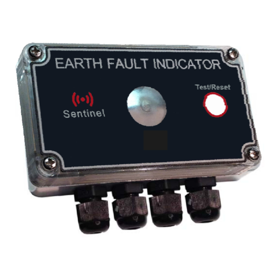
- Page 1 Sentinel™ EFI-MFZ-50 EARTH FAULT INDICATOR USER’S MANUAL...
-
Page 2: Table Of Contents
CONTENTS 1. SAFETY NOTICE ......................3 2. OVERVIEW ........................4 3. FEATURES........................4 4. INSTALLATION .......................4 4.1 CURRENT SENSOR....................4 4.1.1 MULTI-CORE CABLE SYSTEM ................4 4.1.2 SINGLE-CORE CABLE SYSTEM................7 4.2 INDICATING UNIT .....................7 4.3 REMOTE INDICATOR (OPTIONAL)................8 5. OPERATION........................8 5.1 CURRENT SENSOR....................8 5.2 INDICATING UNIT .....................8 5.2.1 AUXILIARY RELAY (OPTIONAL)................9 5.2.2 REMOTE INDICATOR (OPTIONAL) ..............9 5.2.3 MANUAL TEST AND RESET ................9... -
Page 3: Safety Notice
Sentinel™ EFI-MFZ-50 User’s Manual 1. SAFETY NOTICE Review the following safety precautions to avoid serious injury or death and to prevent damage to this product or any products connected to it. To avoid potential hazards, use this product only as specified. This equipment contains high voltages. Electrical shock can cause serious or fatal injury. -
Page 4: Overview
User’s Manual 2. OVERVIEW The Sentinel EFI-MFZ-50 is one of a family of Earth Fault Indicator (EFI) products that is designed to assist in the rapid location and isolation of earth faults on high voltage cable networks. The EFI can be used in radial networks or in openly operated ringed networks. - Page 5 Sentinel™ EFI-MFZ-50 User’s Manual be specified at time of order. The flexible sensor core is mounted on the screened part of the cable, below the stripback point. The core is wrapped around the cable and the cable- tie is pulled tight as far as it will go. A second cable-tie is used to hold the core firmly onto the cable.
- Page 6 Sentinel™ EFI-MFZ-50 User’s Manual FIGURE 1: CURRENT SENSOR MOUNTED ON MULTI-CORE CABLE SYSTEM TERMINATION L1 L2 L3 SCREEN CURRENT SENSOR CURRENT SENSOR OUTGOING CABLE EARTH EQUIVALENT CIRCUIT FIGURE 2: CURRENT SENSOR MOUNTED ON SINGLE-CORE CABLE SYSTEM TERMINATION L1 L2 L3 SCREEN CURRENT SENSOR...
-
Page 7: Single-Core Cable System
Sentinel™ EFI-MFZ-50 User’s Manual 4.1.2 SINGLE-CORE CABLE SYSTEM A larger current sensor (CT300) is available for application on single core cable systems. These systems usually consist of three single-core cables spaced in a row, side-by-side. The flexible sensor core is wrapped tightly around all three cables forming a rectangular oval, and fastened in place with cable-ties. -
Page 8: Remote Indicator (Optional)
Sentinel™ EFI-MFZ-50 User’s Manual 4.3 REMOTE INDICATOR (O PTIONAL A remote indicator can be ordered separately or ordered pre-installed. The remote indicator is designed to be mounted through a hole in the switchgear enclosure so that it is visible from the outside. FIGURE 4: REMOTE INDICATOR 20mm... -
Page 9: Auxiliary Relay (Optional)
Sentinel™ EFI-MFZ-50 User’s Manual The indicating unit is powered from the mains supply and also uses the presence of healthy mains to reset the unit. When healthy mains is first applied or when it returns after a cleared fault condition, the unit will first require up to 5 minutes to charge the onboard supply capacitors before it is functional. -
Page 10: Testing
Sentinel™ EFI-MFZ-50 User’s Manual 6. TESTING The Sentinel EFI can be fully tested by injecting test current though the current sensor. A test procedure is suggested below. 1. Connect the device to mains voltage for at least 5 minutes to charge the supply. 2. -
Page 11: Specifications
Sentinel™ EFI-MFZ-50 User’s Manual 7. SPECIFICATIONS Network voltage range: 1-36kV Rated mains voltage: 110V-230V ±20% Frequency: 50Hz / 60Hz ±20% Overvoltage withstand: 600V for 48 hours Impulse voltage withstand: 10kV, 1.2/50us waveform Trip current: 50A ±10A Minimum fault duration: 2.5 cycles (50ms @ 50Hz / 40ms @ 60Hz) Fault current withstand: 25kA for 1s Primary indication:... - Page 12 Sentinel™ EFI-MFZ-50 User’s Manual -indication method Flashing LED -flash rate: 1Hz nominal -flashing duration: 12 hours nominal Version 3.0 Page 12 of 15...
-
Page 13: Ordering
Sentinel™ EFI-MFZ-50 User’s Manual 8. ORDERING Table 1 below shows the codes to be used for product ordering. Only the first three code groups need to be specified for the standard versions of the product. The standard versions ships without the items from groups 4, 5 and 6, and with a standard size current transformer (CT100 with 3m lead). - Page 14 Sentinel™ EFI-MFZ-50 User’s Manual For Example: ORDERING CODE DESCRIPTION EFI-MFZ-50 (standard version) - Mains powered - Flag indication - 50A trip - CT diameter 100mm, 3m lead EFI-MFZ-50-M5-R7-A2-CT150-C3 - Mains powered - Flag indication - 50A trip - Mains cable, 5m lead - Remote indicator, 7m lead - Auxiliary relay, 2m lead - CT diameter 150mm, 3m lead...
-
Page 15: Warranty
In the event of the above limitation not applying to the user, then in no case shall the Cybertronix cc liability exceed the original purchase price of the product.
Need help?
Do you have a question about the Sentinel EFI-MFZ-50 and is the answer not in the manual?
Questions and answers