Citizen iDP-3550 User Manual
Citizen systems user's manual printer idp-3550, idp-3551
Hide thumbs
Also See for iDP-3550:
- User manual (174 pages) ,
- Service manual (42 pages) ,
- Product manual (24 pages)
Table of Contents
Advertisement
CITIZEN
Manufacturer's Name :
Manufacturer's Address
Declare the Product
Product Name
Model Number(s)
Conform to the following Standards
User's Manual
Model : iDP-3550/3551
Dot Matrix Printer
Rev 1.00 Newly Issued on 01.Mar.1999
Japan CBM Corporation
Information Systems Div.
Declaration of Conformity
: Japan CBM Corporation
: CBM Bldg., 5-68-10, Nakano, Nakano-ku
Tokyo, 164-0001, Japan
Dot Matrix Printer
iDP-3550 Series
(iDP-3550RF/PF, iDP-3550SF/CF, iDP-3550TF/IF)
(S.No.9930001 - )
Advertisement
Table of Contents

Related Manuals for Citizen iDP-3550


Summary of Contents for Citizen iDP-3550
- Page 1 CITIZEN Model : iDP-3550/3551 Rev 1.00 Newly Issued on 01.Mar.1999 Manufacturer’s Name : Manufacturer’s Address Declare the Product Product Name Model Number(s) Conform to the following Standards User's Manual Dot Matrix Printer Japan CBM Corporation Information Systems Div. Declaration of Conformity : Japan CBM Corporation : CBM Bldg., 5-68-10, Nakano, Nakano-ku...
- Page 2 : EN61000-3-3 : 1995 : EN61000-4-4 : 1995 : EN61000-4-5 : 1995 : EN61000-4-6 : 1996 3V, 0.15MHz-80MHz AM 1KHz 80% : EN61000-4-8 : 1993 50Hz, 3A/m : EN61000-4-11 : 1994 0%, 500ms/40%, 100ms/70%, 10ms Supplementary Information “The product complies with the requirements of the Low Voltage Directive 73/23/EEC, 93/68/EEC and the EMC Directive 89/336EEC, 92/31/EEC, 93/68EEC”...
-
Page 3: Important Safety Instructions
IMPORTANT SAFETY INSTRUCTIONS •Read all of these instructions and save them for future reference. •Follow all warnings and instructions marked on the product. •Unplug this product from the wall outlet before cleaning. Do not use liquid or aerosol cleaners. Use a damp cloth for cleaning. - Page 4 grundsätzlich Stecker aus der Steckdose ziehen. Keine Flüssigkeiten oder Aerosolreiniger benutzen. Nut mit einem feuchten Tuch abwischen. •Der Drucker darf nicht in der Nähe von Wasser aufgestellt werden. •Drucker nicht auf einem unstabilen Wagen, Stand oder Tisch aufstellen. herunterfallen und dabel beschädigt werden. •Schlitze und Öffnungen im Gehäuse, in der Rückwand und im Boden dienen der Belüftung.
- Page 5 IMPORTANT: This equipment generates, uses, and can radiate radio frequency energy and if not installed and used in accordance with the instruction manual, may cause interference to radio communications. It has been tested and found to comply with the limits for a Class A computing device pursuant to Subpart J of Part 15 off FCC Rules, which are designed to provide reasonable protection against such interference when operated in a commercial environment.
- Page 7 SAFETY PRECAUTIONS ----- BE SURE TO OBSERVE In order to prevent hazards to an operator or other persons and damage to property, be sure to observe the following precautions. The following describes the degrees of hazard and damages that can occur if the given instructions are neglected or the equipment is incorrectly operated.
- Page 8 Never handle the equipment in the following manners, as it may break, become out of order, or overheat causing smoke and resulting in fire or electric shock. If the equipment is used in an abnormal condition, such as when broken, then problems, smoke emission, abnormal odor/noise, and fire can result.
-
Page 9: Precautions For Installation
There is a danger of fire or electric shock. • Do not put any object on the printer. It may cause trouble. • Do not use the equipment near a radio or TV receiver. Do not share the power from a plug socket a radio or TV receiver is connected to. -
Page 10: Precautions For Handling
• Never use a pointed object, such as a pen, to operate the operation panel. • Do not use Scotch tape to fasten paper together for continuous use. • Never pull the set paper forcibly. When opening/closing the printer cover, take care that the paper will not be caught. -
Page 11: Daily Maintenance
• Prior to starting maintenance work, be sure to turn off the main body. • Use a dry soft cloth to wipe off stains and dust from the surfaces of the main body case. For severe soiling, dip the cloth in water and wring it, for wiping off the soil. Never use organic solvents, such as alcohol, thinner, trichlene, benzene, ketone, or chemical dusters. -
Page 12: Table Of Contents
Recommended Paper...4 2.3.2 Printing Position...4 2.3.3 Cutter Layout ...4 3. OUTER APPEARANCE AND COMPONENT PARTS... 5 iDP-3550...5 iDP-3551...6 4. OPERATION ... 8 Detaching/Attaching the Printer Cover ...8 Connecting the Interface Cable ...8 Connecting the Drawer Kick-Out Connector ...9 Opening/Closing the Auto Cutter (iDP-3551)...9 Setting the Ribbon Cassette...10... - Page 13 15.10 Code Page 865...117 15.11 Code Page 852...118 15.12 Code Page 866...119 15.13 Code Page 857...120 15.14 Windows Code ...121 15.15 International Character Codes Table ...122 APPENDIX 1. BLOCK DIAGRAM ... 123 APPENDIX 2. OUTLINE DRAWING for iDP-3550 ... 124...
- Page 14 APPENDIX 3. OUTLINE DRAWING for iDP-3551 ... 125...
- Page 15 4. BETRIEB... 133 Druckerabdeckung Aufsetzen, Entfernen...133 Anschluß des Schnittstellenkabels ...134 Anschluß des Schubladenausschubsteckers ...135 Öffnen/Schließen des automatischen Schneidemechanismus (iDP-3551)...135 Einlegen der Farbbandkassette ...135 Einlegen des Papiers...136 Hintere Abdeckung des Druckers aufsetzen...138 Herausnehmen der Restpapierrolle...138 Beseitigung von Papierstaus...139 4.10 Initialisierung des Schneidemechanismus...139 4.11 Bedienfeld und Fehleranzeigen ...139 5.
-
Page 16: Outline
This is a small-size dot impact printer developed for various data communication terminals, POS terminals, kitchen-use printers, and so on. Its abundant built-in features allow you to widely use this printer for different applications. Prior to using it, read and understand this manual thoroughly. -
Page 17: Basic Specifications
BASIC SPECIFICATIONS Model Classifications The printer model is classified by the following designation method. iDP-3550 - R F 120 C Type C: Character Type (DP654-DFCS Printer Mechanism) G: Graphic Type (DP657-DFGS Printer Mechanism) Supply Voltage 120: For 120 V AC... -
Page 18: Basic Specifications
Provided by operating the power, LF, and SEL switches. Input buffer 6 KB or 256 bytes (Selectable with the DIP switch) Buff er ba ckup func t ion Within 24 hours (After 10 minutes or more of printer operation) Drawer function 2-drawer, 1-drawer switch Auto loading function Automatically feeds the paper by several lines when it is inserted. -
Page 19: Paper Specifications
DP-654: Approx. 6.3.6 mm DP-657: Approx. 58.7 mm : Approx. 28 mm : Approx. 19 mm DP-654: Approx. 6.2 mm DP-657: Approx. 8.65 mm Cutting position iDP-3550 : Approx. 28 mm iDP-3551 : Approx. 19 mm Center of the first printing line... -
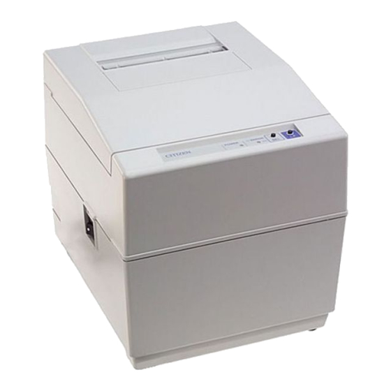
Page 20: Outer Appearance And Component Parts
OUTER APPEARANCE AND COMPONENT PARTS iDP-3550 SEL/ERROR Lamp POWER Lamp Upper Cover SEL Switch Bottom Cover LF Switch Paper Holder Power Switch Rear Cover Power Cord Plug Interface Connector Winder Connector Drawer Kick-Out Connector... -
Page 21: Idp-3551
iDP-3551 SEL/ERROR Lamp POWER Lamp Upper Cover SEL Switch Bottom Cover LF Switch Paper Holder Power Switch Rear Cover Power Cord Plug Interface Connector Winder Connector Drawer Kick-Out Connector... - Page 22 Changes between select and deselect status. Also used to cancel the alarm status. (In ESC/POS mode, only used to cancel the alarm.) (7) Interface connector Uses a cables to connect to a personal computer. Check that the computer and printer are turned off when connecting. (8) External output connector Drawer control connector.
-
Page 23: Operation
OPERATION Detaching/Attaching the Printer Cover 1. Use both hands to hold the projections on each side of the printer cover and lift the printer cover in the direction shown by the arrow to detach it. 2. When attaching the printer cover, place the hooked part at the front in the appropriate part of the printer and lower the printer cover. -
Page 24: Connecting The Drawer Kick-Out Connector
2. Check the top and bottom of the drawer kick-out cable connector and connect it to the drawer kick-out connector located at the lower section of the printer. 3. Screw the grounding cable of the drawer to the grounding terminal located at the lower section of the printer. -
Page 25: Setting The Ribbon Cassette
4. If the ribbon is slackened, turn the knob in the direction shown by the arrow to give the tension before placing it in the printer. 5. Push teh locking claws into the holder of the printer as you place the ribbon between the print head and ribbon guide. A click sound will be heard. -
Page 26: Inserting The Paper
5. Insert the end of the paper roll straight into the paper inlet slot (Indicated by the arrow). 6. The paper is automatically fed in and comes out the paper outlet of the printer (Paper outlet of the auto cutter for the iDP-3551). -
Page 28: Attaching The Rear Cover
Attaching the Rear Cover Insert the claws of the rear cover into the square holes at the back of the printer, and move the rear cover in the direction of the arrow to close it. How to Remove Remaining Paper Roll 1. -
Page 29: Unlocking The Cutter (Idp-3551)
4.10 Unlocking the Cutter (iDP-3551) 1. Detach the printer cover. 2. Press the LF switch. The auto cutter is initialized to return its blade and clear an alarm. 3. If the paper is jamming, eliminate the jamming paper completely, seeing "4.9 Removing Paper Jam."... -
Page 30: Operation Panel And Display Of Error
SEL/ERROR lamp will blink to stop the printer mechanism. : If the printer has run out of paper, the paper sensor in the paper path near the print head will detect the end of the paper roll, turn on the buzzer, and blink the SEL/ERROR lamp to stop the printer mechanism. - Page 31 ERROR lamp lights up. Waits for data input When the power is turned on while the LF and SEL switches are pressed, the printer enters dump mode and prints the following message. “=== Hexadecimal Dump ===” •SEL/ERROR lamp blinks at intervals of 0.25 sec.
-
Page 32: Dip Switch Setting
DIP SWITCH SETTING Location of DIP Switch 1. Turn off the power. 2. Remove the printer cover. 3. The DIP switch can be found at the location shown in the figure below. (Only DSW2 is available for the serial interface.) -
Page 33: Dip Switches Setting
DIP Switches Setting 1) DIP Switch 1 Function DSW1-1 Auto cutter DSW1-2 International characters DSW1-3 DSW1-4 DSW1-5 CBM command DSW1-6 CR mode DSW1-7 Mechanism type DSW1-8 Buffer size DSW1-9 Operation mode DSW1-10 *1, *3 : Depends on the type. : Depends on the destination. : Effective only when CBM mode is selected with DSW1-9 and -10. - Page 34 2) DIP Switch 2 Function DSW2-1 Bit length DSW2-2 Parity DSW2-3 Odd/Even DSW2-4 Communication mode DSW2-5 Baud rate DSW2-6 DSW2-7 DSW2-8 Unused Baud rate Baud rate DSW2-5 1200 2400 4800 9600 19200 The DIP switch 2 is used only for the serial interface. 8 bits 7 bits Even...
-
Page 35: Preset Jumper Setting
6. PRESET JUMPER SETTING Location of Preset Jumper (1) Turn off the power. (2) The preset jumper is set at the time of shipment from the factory. If the settings are to be changed, do so by removing the control board and changing the setting as indicated in the service manual. The location of the preset jumpers is shown in the figure below. -
Page 36: Mode Setting Method
MODE SETTING METHOD This printer has the CBM, STAR, and ESC/POS mode. Any desired mode can be selected and set according to your need. (1) Setting method • See 5 “DIP SWITCH SETTING”. • Seeing the settings of the DIP switch segments 1-9 and 1-10 and those of the preset jumper, set each... -
Page 37: Input Buffer Backup Function
Even if the power is turned off or fails during the printing process, the data in the input buffer will be saved. If the power is turned on again, the printer will print a power failure mark, "==POWER DOWN==," in red and reprints the data from the beginning of the line where it left off. -
Page 38: Parallel Interface
BUSY PE(HI-LEVEL) SELECT FRAME GND : 8-bit parallel system (DATA1 to DATA8) : ACK, BUSY, STB, FAULT, SELECT, RESET, COMPULSION : Printer side --- 57LE-40360 (Anphenol), or equivalent Cable side --- 57-30360 (Anphenol), or equivalent Mode STAR ESC/POS TWISTED PAIR GND... -
Page 39: Input And Output Signals
(Active “High”) • FAULT : A signal turned to "Low" when the printer has an alarm. At this time, all the control circuits in the printer stop. (Active “Low”) • SELECT : A signal to show whether the printer is selected (On-line) or deselected. (Active “High”) -
Page 40: Electrical Characteristics
"LOW" level : 0.4 V at maximum (3) Input and output conditions All the input signals are pulled up with a 3.3 k resistor. [Printer Side] All the output signals are pulled up with a 3.3k resistor. [Printer Side] [Host Side]... -
Page 41: Timing Chart
(1) Data input and printing timing 9.3.4 Data Receiving Control When the BUSY signal is at "LOW," the printer can receive the data from the host, but when at "HIGH," it cannot. T1, T2, T3 : 0.5 s MIN : 270 ns MAX : 2.3 s TYP... -
Page 42: Serial Interface
10. SERIAL INTERFACE 10.1 Specifications (1) Synchronous system: Asynchronous (2) Baud rate: 150, 300, 600, 1200, 2400, 4800, 9600, or 19200 bps (User selectable) (3) Configuration of one word •Start bit : 1 bit •Data bits : 7 or 8 bits (User selectable) •Parity bit : Odd, even, or none (User selectable) •Stop bit... -
Page 43: Connector's Pin Configuration
10.2 Connector's Pin Configuration Mode PE (HI-LEVEL) Cautions: 1. An RS-232C signal is based on the EIA RS-232C. 2. When the data is not being transferred, the received data should be always maintained as a mark. STAR FAULT FAULT mTXD mRXD RESET ECS/POS... -
Page 44: Input And Output Signals
(4) DSR When this signal is a space, the data is sent from the printer side. Note that if this signal is a mark when a request to send command is executed, the printer will wait until the signal becomes a space. - Page 45 (8) RCH When the printer is ready to receive, this signal is turned to Space. This signal line is the same as DTR. (9) mTXD TXD signal for the diode gate. (10) mRXD RXD signal for the diode gate. (11) FG This is a Frame Ground signal.
-
Page 46: Data Configuration
10.3.2 Data Configuration Mark Space (1) Start bit After a lapse of 1/2 bit from a mark-to-space fall edge, the state is read again, and if it is a space, it is recognized as the start bit. If it is a mark, it is assumed neither the start bit nor an error, and it is attempted to detect the start bit again. -
Page 47: Error Detection
The DTR and TXD signals are available as control signals to transfer the data to the input buffer. 10.3.6 Electrical Characteristics (1) RS-232C circuit Input (RXD, DSR, mRXD) [Printer Side] Equivalent to MAX232 Output (DTR, TXD, mTXD, RCH, RTS, FAULT) [Host Side]... - Page 48 Space=(+8V): At Ready (2) Others •RESET : A signal to reset the entire printer. •PE : A signal to show that the paper has run out. Normal at the "LOW" level, but turned to the "HIGH" level when the paper has run out.
-
Page 49: Drawer Kick-Out Connector
11. DRAWER KICK-OUT CONNECTOR 11.1 Specifications of Drawer Kick-Out Connector (1) Drawer kick-out drive signal Parallel ----- Can be learned at the no. 34 pin of the interface connector Serial ----- Provided with a command to learn the status in the STAR and ESC/POS modes. (2) Electrical characteristics 1) Drive voltage: 24 V DC 2) Drive current: 0.8 A at maximum (Within 510 ms) -
Page 50: Winder Connector
12. WINDER CONNECTOR 12.1 Specifications of Winder Connector (1) Winder drive signal The winder drive signal is output synchronous with the LF signal. (2) Electrical characteristics 1) Drive voltage: 24 V DC 2) Drive current: 0.8 A at maximum 12.2 Connector's Pin Configuration Signal Connector used... -
Page 51: Maintenance And Service
13. MAINTENANCE AND SERVICE For the information on maintenance and service, please contact our dealer or at the following address. Northern America CBM America Corporation Service Center 365 Van Ness Way Suit 510 Torrance, CA 90501, U.S.A TEL +1-310-781-1460 FAX +1-310-781-9157 Other Areas Japan CBM Corporation Information Systems Division... -
Page 52: Print Control Functions
Specifying the double width character SI (Note) Canceling the double width character Printing and paper feed Printing DC 1 (Note) Initializing the printer DC 2 (Note) Specifying/Canceling the Inverted character DC 3 (Note) Specifying the red print 10 CAN Canceling the print data... - Page 53 Command Code Canceling the double width character Specifying the double width character Command Code Selecting the printer Specifying the red print Deselecting the printer Function 8-bit data selected Function 7-bit data selected...
-
Page 54: Description Of Items
14.1.2 Description of Items XXXX [Function] Command name [Code] A row of command constituent code is represented by a hexadecimal number with < >H, binary number with < >B, and a decimal number with < >. [ ]k means a repeat count of k- times. - Page 55 Details FF n [Function] n-line paper feed [Code] <0C>H n [Range] 1 n 127 [Outline] This command feeds the paper by n-lines. You can set n = 1 to 127 lines. If the print buffer contains the data, use of this command feeds the paper by n-lines after printing the data. Setting n = 0 does not feed the paper.
- Page 56 This command prints the data. If the DIP switch segment 1-6 is set to OFF, the printer will print the data in the print buffer and feed the paper by one line. If it is set to ON, the printer will print the data in the print buffer and will not feed the paper. [Function]...
- Page 57 This command specifies red-color characters. All the characters in one line are printed in red by prefixing the print data with this command and sending it to the printer. When you want to use red characters, use this command for each line.
- Page 58 This command specifies red-color characters. All the characters in one line are printed in red by prefixing the print data with this command and sending it to the printer. When you want to use red characters, use this command for each line.
- Page 59 ESC " " n1 n2 [Function] Specifying the bit image mode [Code] <1B>H <2A>H n1 n2 [Range] 1 n1 + 256 1 n1 + 256 [Outline] This command allows printing in the bit image mode. Divide the number of dots printed by 256 and assume its quotient to be n2 and remainder to be n1.
- Page 60 [Outline] Only effective for Graphic type. This command sets the line feed width to 2/9 inch. ESC "3" [Function] Setting the standard line feed width [Code] <1B>H <33>H [Outline] This command sets the line feed width as follows. Character type: Graphic type: 1/6 inch 2/9 inch...
- Page 61 ESC "C" n [Function] Setting the page length [Code] <1B>H <43>H n [Range] 1 n 127 [Outline] Sets the 1-page length to n-lines. ESC "N" n [Function] Specifying the perforation skip [Code] <1B>H <4E>H n [Range] 1 n 126 [Outline] This command feeds (skips) the lines specified with n without printing.
- Page 62 ESC "f" 1 [Function] Form feed (Changing the page) [Code] <1B>H <66>H <01>H [Outline] This command searches for the beginning of the next page after printing the data in the print buffer. ESC "t" n [Function] Selecting the character code table [Code] <1B>H <74>H n [Range]...
- Page 63 ESC BEL n1 n2 [Function] Setting the external device drive pulse width [Code] <1B>H <07>H n1 n2 [Range] 1 n1 127 [Outline] This command sets the power-on time to drive an external device (such as cash drawer). Power-on time = n1 10 (ms) Delay time = n2 10 (ms) To actually drive the drawer, use the BEL and FS commands.
- Page 64 As soon as this command is received, the drawer connector No. 5 pin is driven. The power- on time is 200 ms ON and 200 ms OFF stationary. The drawers 1 and 2 cannot be driven simultaneously. [Function] Buzzer-on [Code] <1E>H [Outline] This command emits a short warning sound from the printer.
- Page 65 ESC "P" 0 [Function] Full cut [Code] <1B>H<50>H<00>H [Outline] This command fully cuts the paper. ESC "P" 1 [Function] Partial cut [Code] <1B>H<50>H<01>H [Outline] This command partially cuts the paper. ESC "R" n [Function] Selecting the international character set [Code] <1B>H <52>H n [Range] 0 n 10...
- Page 66 ESC "&" <0> n1 n2 [m0 m1 ... m5 m6 m7 m8 m9] n2 - n1 + 1 [Function] Defining the Download character set [Code] <1B>H <26>H <00>H n1 n2 [m0 m1 ... m5 m6 m7 m8 m9] n2 - n1 + 1 [Range] 32 n1 n2 255 m0 = 0 or m0 = 128 [Outline]...
- Page 67 This command selects/deselects the download character set. The download characters cannot be printed by simply defining them with the above-mentioned ESC & 0 command. To print them, send this command to the printer. ESC " " n "data" CR or LF...
- Page 68 ESC DC3 n [Function] Printing the message [Code] <1B>H <13>H n [Range] 1 n 10 [Function] This command prints a message. If the value of n is specified beyond the range, the message will not be printed. ESC "y" n [Function] Setting the print lines after paper near end detection [Code]...
- Page 69 ESC DC2 n1 n2 [Function] Deleting the download character, message, bit image [Code] <1B>H <12>H n1 n2 [Range] 0 n1 3 0 n2 [Outline] This command deletes the downloaded characters, message, and bit image. All(Message, characters, bit image) Download message Download characters Download bit image With n2, specify which data of the function specified with n1 should be deleted.
- Page 70 GS "*" n1 n2 [d] n1 n2 8 [Function] Defining the download bit image [Code] <1D>H <2A>H <n1> <n2> [<d>] n1 n2 8 [Range] 1 n1 45 Note) Take care that the number of data (n1 n2 8) is equal to or smaller than 2,048. [Outline] This command defines the download bit image having the dots specified n1 and n2.
- Page 71 GS " " m [Function] Printing the download bit image [Code] <1D>H <2F>H m [Range] [Outline] This command prints the bit image saved in the number specified with m. [Caution] If the print buffer contains the data, this command will be ignored. If the bit image has not been saved in the specified number, this command will be ignored.
-
Page 72: Star Mode
14.2 STAR Mode 14.2.1 Command List Command ESC R n Sel ecting the inte rnati onal chara cter set ESC 6 ESC 7 ESC M ESC P ESC : Specifying the double width character Canceling the double width character ESC E Specifying the highlight character 10 ESC F Canceling the highlight character... - Page 73 Setting the deselect mode 49 DC1 Setting the Select mode Unidirectional/bidirectional print mode selection 50 ESC U n command 51 ESC @ Initializing the printer 52 ENQ Enquiry 53 STX Text start 54 ETX Text end command ESC d 0 Full cut ESC d <0>...
- Page 74 Details ESC "R" n [Function] Selecting the international character set [Code] <1B>H <52>H n [Range] 0 n 10 [Outline] This command selects the international characters according to the value of n. [Default] Depends upon DIP switch setting. [Function] Specifying the double width character [Code] <0E>H [Outline]...
- Page 75 [Function] Canceling the double width character [Code] <14>H [Outline] This command deselects the double width characters set with SO. The data following this command will be printed in ordinary characters. ESC "E" [Function] Specifying the highlight character [Code] <1B>H <45>H [Outline] The data following this command is printed in highlight (double) characters.
- Page 76 ESC " " n [Function] Specifying/Canceling the underline [Code] <1B>H <2D>H n [Outline] This command selects/deselects an underline. The underline is selected at n = 1 and deselected at n = 0. The space by the horizontal tab is not underlined. ESC "4"...
- Page 77 [Function] Specifying the inverted character [Code] <0F>H [Outline] This command selects and prints the inverted characters. Enter it at the beginning of one line. Otherwise, it will be invalid. Erect and inverted characters cannot be mixed in one line. [Function] Canceling the Inverted character [Code] <12>H...
- Page 78 [Function] Printing and paper feed (Same as LF) [Code] <0D>H [Outline] The function is the same "LF." However, if the DIP switch segment 1-6 is set to ON, this command is ignored. ESC "z" [Function] Setting the standard line feed width [Code] <1B>H <7A>H [Outline]...
- Page 79 [Function] Form feed (Changing the page) [Code] <0C>H [Outline] This command searches for the head of the next page after printing the data in the print buffer. ESC "C" n [Function] Setting the n-line page length [Code] <IB>H <43>H n [Range] 1 n 255 [Outline]...
- Page 80 [Function] Vertical tab [Code] <0B> H [Outline] This command feeds the paper to the next vertical tab position. It cannot be fed unless the vertical tab position has been set. If the current position is equal to or greater than the maximum set vertical tab position, it will be fed to the head of the next page.
- Page 81 ESC "N" n [Function] Setting the lower margin [Code] <1B>H <4E>H n [Range] 0 n 255 [Outline] This command sets the n-line lower margin. [Default] n = 0 ESC "O" [Function] Canceling the lower margin [Code] <1B>H <4F>H [Outline] This command deselects the set lower margin. ESC "l"...
- Page 82 ESC "Q" n [Function] Setting the right margin [Code] <1B>H <51>H n [Range] 2 n (Max. print columns) [Outline] This command sets the right margin and printing is performed up to n-columns. [Function] Horizontal tab [Code] <09>H [Outline] This command moves a printing position to the preset next horizontal tab position. This command will be ignored unless there is the next horizontal tab position.
- Page 83 ESC "D" n1 n2 NUL [Function] Setting the horizontal tab position [Code] <1B>H <44>H n1 n2 <00>H [Range] 1 n Max. print columns – 1 1 k 16 [Outline] This command sets the horizontal tab positions. n indicates the number of lines from the head of the line to the horizontal tab setting position.
- Page 84 ESC "1" [Function] Setting the 1/9-inch line feed width [Code] <1B>H <31>H [Outline] This command sets the line feed width to 1/9 inch. ESC "2" [Function] Setting the 2/9-inch line feed width [Code] <1B>H <32>H [Outline] This command sets the line feed width to 2/9 inch. (G raphic Type) (Graphic Type)
- Page 85 This command prints the bit image by the number of data specified with n1. Printing will be unidirectional. The surplus data exceeding the printable quantity in one line will be ignored. The printer will automatically return to the character mode after printing the bit image. (Graphic Type)
- Page 86 The surplus data exceeding the printable quantity in one line will be ignored. The printer will automatically return to the character mode after printing the bit image. The relations between the printing head pin numbers and the data are the same as the 8-dot standard density bit image command, <ESC>...
- Page 87 ESC "&"<O> n1 n2 [m0 m1 m2 m3 m4 m5 m6 m7 m8 m9] n2 - n1 + 1 [Function] Defining the download character set [Code] <1B>H <26>H <00>H n1 n2 [m0 m1 ... m5 m6 m7 m8 m9] n2 - n1 + 1 [Range] 32 n1 n2 255, m0 = 0 or m0 = 128 [Outline]...
- Page 88 <IB>H <25>H n [Outline] This command selects/deselects the download character set. The download characters cannot be printed by simply defining them with the above-mentioned ESC & 0 command. To print them, send this command to the printer. Download Character Set Deselects Selects...
- Page 89 ESC BEL n1 n2 [Function] Setting the external device drive pulse width [Code] <1B>H <07>H n1 n2 [Range] 1 n1 127 1 n2 127 [Outline] This command sets the power-on time to drive an external device(cash drawer). Power-on time = n1 10 (ms) Delay time = n2 10 (ms) To actually drive the drawer, use the <BEL>...
- Page 90 As soon as this command is received, the drawer connector no. 5 pin is driven. The power- on time is 200 ms ON and 200 ms OFF stationary. The drawers 1 and 2 cannot be driven simultaneously. [Function] Buzzer-on [Code] <1E>H [Outline] This command emits a short warning sound from the printer.
- Page 91 If the printer receives <DC3>, it will ignore the subsequent data. The Deselect mode is cancelled by <DC1>. [Function] Setting the select mode [Code] <11H> [Outline] If the printer receives this command, it will save the subsequent data in the input buffer.
- Page 92 ESC "@" [Function] Initializing the printer [Code] <1B>H <40>H [Outline] This command cancels various conditions set after power-on to initializes the printer to the conditions having existed at power-on. However, the input buffer is not initialized. Bidirectional print Unidirectional print...
- Page 93 <05>H [Outline] This command is valid only for the serial interface. The printer sends the status information. If this command is entered after receiving the text information in the STX-ETX mode, the printer will send the status information and check byte.
- Page 94 [Function] Text end [Code] <03>H [Outline] This command is valid only for the serial interface. It ends the STX-ETX mode and prints the data.
- Page 95 Sends STX Odd Parity Check ? Sets Test Byte To Exclusive ORs Test Byte and Sent Data Test Byte Sends Data to Printer Last Data in 1 Block ? Sends ENQ Receives Status Receives Check Byte Status Error ? Check Byte...
- Page 96 ESC "d" "0" or ESC "d" <0> [Function] Full cut [Code] <1B>H<64>H<30>H or <IB>H<64>H<00>H [Outline] This command fully cuts the paper. ESC "d" "1" or ESC "d" <1> [Function] Partial cut [Code] <1B>H<64>H<31>H or <1B>H<64>H<01>H [Outline] This command partially cuts the paper. ESC "t"...
- Page 97 ESC " " n "data" CR or LF [Function] Defining the message [Code] <1B>H <2F>H n "data" CR or LF [Range] 1 n 10 [Outline] This command can define up to a 50-byte message in one line. If the value of n is specified beyond the range, the data following n will be treated as the print data.
- Page 98 ESC "y" n [Function] Setting the print lines after paper near end detection [Code] <1B>H<79>H n [Range] 0 n1 255 [Outline] This command sets the number of print lines after paper near end detection. It stops printing after printing n state (See 4.11 Operation Panel and Display of Error).
- Page 99 GS "*" n1 n2 [d] n1 n2 8 [Function] Defining the download, bit image [Code] <1D>H <2A>H <n1> <n2> [<d>] n1 n2 8 [Range] 1 n1 45 0 Note) Take care that the number of data(n1 n2 8) is equal to or smaller than 2,048. [Outline] This command defines the download bit image having the dots specified n1 and n2.
- Page 100 GS m [Function] Printing the download bit image [Code] <1D>H <2F>H m [Range] [Outline] This command prints the bit image saved in the number specified with m. [Caution] If the print buffer contains the data, this command will be ignored. If the bit image has not been saved in the specified number, this command will be ignored.
-
Page 101: Esc/Pos Commands
25 ESC t n Selecting the character code table 26 ESC u n Sending the status for peripheral devi ce 27 ESC v Sending the printer status 28 ESC { n Specifying/Canceling the inverted character print 29 GS E n 30 ESC n... - Page 102 Details [Function] Horizontal tab [Code] <09>H [Outline] This command moves a printing position to the next horizontal tab position. If the next horizontal tab position is not set, this command will be ignored. [Caution] The horizontal tab position is set by <ESC> D. Initial setting of the horizontal tab position is every 8 characters (9th, 17th, 25th culomns, and so on).
- Page 103 This command prints the data. If the DIP switch segment 1-6 is set to OFF, the printer will print the data in the print buffer and feed the paper by one line. If it is set to ON, the printer will print the data in the print buffer and will not feed the paper.
- Page 104 ESC "!" n [Function] Setting the print mode batch [Code] <1B>H <21>H n [Range] 0 n 255 [Outline] Sets the print mode. "n" (Each bit) has the following meanings. [Caution] The entire character print width is underlined, but the portion skipped by HT is not. If both double height and double width are selected, the characters will be quadrupled.
- Page 105 ESC "%" n [Function] Specifying/Canceling the download character set [Code] <1B>H <25>H n [Range] 0 n 255 [Outline] This command selects/deselects the download character set. n is valid only for the least significant bit. Setting n0 = 1 selects the download character set. Setting n0 = 0 deselects the download character set.
- Page 106 ESC "&" s n m [a[p] s a]m - n + 1 [Function] Defining the download character set [Code] <1B>H <26>H s n m [a[p] ... <ps a>] m - n + 1 [Range] s = 2 32 n m 0 p1 ...
- Page 107 ESC "*" m n1 n2 [d] n1 + 256 n2 [Function] Specifying the bit image mode [Code] <1B>H <2A>H m n1 n2 [d] n1 + 256 2 [Range] m = 0, 1 0 n1 255 0 n2 3 0 d 255 [Outline] This command specifies the bit image for the mode m as to the number of dots specified with n1 and n2.
- Page 108 <1B>H <40>H [Outline] This command cancels various conditions set after power-on to initializes the printer to the conditions having existed at power-on. However, the print buffer, input buffer, and external device drive pulse width are not initialized. The settings of the DIP switch segments are not re-read.
- Page 109 ESC "D" [n]k NUL [Function] Setting the Horizontal tab position [Code] <1B>H <44>H [n]k <00>H [Range] 1 n 255 0 k 32 [Outline] This command sets the horizontal tab position. n denotes the number of columns from the head of the line to the horizontal tab setting. k denotes the number of horizontal tab positions to be set.
- Page 110 ESC "R" n [Function] Selecting the international character set [Code] <1B>H <52>H n [Range] 0 n 10 [Outline] This command selects the international characters according to the value of n. [Default] Depends upon DIP switch setting. Character Set U.S.A. France Germany U.K.
- Page 111 [Caution] If unidirectional print is selected, the printer will print from the left to the right. When you want to prevent horizontal shear in printing at high accuracy, specify unidirectional print with this command. (For double height print, etc.)
- Page 112 ESC "c" "4" n [Function] Selecting the paper near end sensor valid for print stop [Code] <1B>H<63>H<34>H n [Range] 0 n 255 [Outline] This command selects the no-paper detector state in which printing should be stopped. [Default] n = 0 ESC "c"...
- Page 113 ESC i [Function] Full cut [Code] <1B>H<69>H [Outline] This command fully cuts the paper. ESC m [Function] Partial cut [Code] <1B>H<6D>H [Outline] This command partially cuts the paper. (iDP3551 Only) (iDP3551 Only)
- Page 114 (It is recommended to make n2 four times higher or more than n1.) The drawer kick-out solenoid should have a resistance value of 36 lower one because an overcurrent will flow. For the drawer power, be sure to use the printer power (Drawer kick-out connector No. 4 pin).
- Page 115 ESC "r" n [Function] Selecting the printing color [Code] <1B>H <72>H n [Range] n = 0, 1 [Outline] This command selects a print color for each line. Setting n = 0 selects black. Setting n = 1 selects red. The command is valid only when it is entered at the head of the line. [Default] n = 0 (Black print) ESC "t"...
- Page 116 0 will be always "1". In case of DTR/DSR control, if the host cannot receive (DSR signal has the Mark status), the printer will wait until it will be ready to receive. In case of XON/XOFF control, only one byte will be sent without confirming the status of the DSR signal.
- Page 117 [Code] <1B>H <76>H [Outline] This command sends the printer status. [Caution] This command is valid only for the serial interface. The following table lists the status sent. In case of DTR/DSR control, only one byte will be sent after confirming that the host is ready to receive (DSR signal has the Space status).
- Page 118 ESC "{ " n [Function] Specifying/Canceling the inverted character print [Code] <1B>H <7B>H n [Range] 0 n 255 [Outline] This command selects/deselects inverted print. n is valid only for the least significant bit. [Caution] This command is valid only if entered at the head of the line. [Default] n = 0 ESC "...
- Page 119 ESC DC3 n [Function] Printing the message [Code] <1B>H <13>H n [Range] 1 n 10 [Function] This command prints a message. If the value of n is specified beyond the range, or if the message is not registered yet the message will not be printed. ESC "y"...
- Page 120 ESC DC2 n1 n2 [Function] Deleting the download character, message, bit image [Code] <1B>H <12>H n1 n2 [Range] 0 n1 3 0 n2 [Outline] This command deletes the downloaded characters, message, and bit image. All(Message, characters, bit image) Download message Download characters Download bit image With n2, specify which data of the function specified with n1 should be deleted.
- Page 121 GS "*" n1 n2 [d] n1 n2 8 [Function] Defining the download bit image [Code] <1D>H <2A>H <n1> <n2> [<d>] n1 n2 8 [Range] 1 n1 45 0 n2 24 Note) Take care that the number of data(n1 n2 8) is equal to or smaller than 2,048. [Outline] This command defines the download bit image having the dots specified n1 and n2.
- Page 122 GS m [Function] Printing the download bit image [Code] <1D>H <2F>H m [Range] [Outline] This command prints the bit image saved in the number specified with m. [Caution] If the print buffer contains the data, this command will be ignored. If the bit image has not been saved in the specified number, this command will be ignored.
-
Page 123: Character Codes Table
15. CHARACTER CODES TABLE 15.1 CBM (Domestic) -
Page 124: Cbm (International)
15.2 CBM (International) -
Page 125: Star (Domestic)
15.3 STAR (Domestic) -
Page 126: Star (International)
15.4 STAR (International) -
Page 127: Code
15.5 Code Page 437... -
Page 128: Katakana
15.6 Katakana... -
Page 129: Code
15.7 Code Page 850... -
Page 130: Code
15.8 Code Page 860... -
Page 131: Code
15.9 Code Page 863... -
Page 132: Code
15.10 Code Page 865... -
Page 133: Code
15.11 Code Page 852... -
Page 134: Code
15.12 Code Page 866... -
Page 135: Code
15.13 Code Page 857... -
Page 136: Windows Code
15.14 Windows Code... -
Page 137: International Character Codes Table
15.15 International Character Codes Table... -
Page 138: Appendix 1. Block Diagram
APPENDIX 1. BLOCK DIAGRAM Parallel (CENTRONICS Compliant) Interface Serial (RS-232C Compliant) Paper Near Control Operation Panel Print Head Driver Printer DC Motor/ Mechanism LF Solenoid/ DP-654C CC Solenoid/ Drivers DP-657G Mechanism Control Signals/ PE Signal Power Supply 120 V AC, 50/60 Hz... -
Page 139: Appendix 3. Outline Drawing For Idp-3551
APPENDIX 2. OUTLINE DRAWING for iDP-3550 Unit: mm... - Page 140 APPENDIX 3. OUTLINE DRAWING for iDP-3551...
- Page 141 <<< German >>>...
- Page 142 1. Bitte lesen Sie die Bedienungsanleitung vor dem Betrieb des Geräts aufmerksam durch und bewahren Sie die Anleitung anschließend für späteres Nachschlagen an einem sicheren Platz auf. 2. Änderungen des Inhalts dieser Anleitung bleiben ohne Vorankündigung vorbehalten. 3. Die Vervielfältigung dieser Bedienungsanleitung ohne vorherige Genehmigung verstößt, auch auszugsweise, gegen das Urheberschutzrecht.
- Page 143 ZU BEACHTENDE SICHERHEITSMASSREGELN Zur Vermeidung von Gefahren gegenüber dem Bediener und anderen Personen und Sachschäden sind die folgenden Vorsichtsmaßregeln unbedingt zu beachten. Der folgende Text beschreibt das Ausmaß der Gefahren und potentiellen Sachschäden, die durch eine Mißachtung der Bedienungshinweise oder durch die unsachgemäße Handhabung des Geräts entstehen können.
- Page 144 Bei m Bet rieb des Geräts sind die nachf olgenden Vorsic htsma ßrege ln unbedingt zu beac hten. Eine Mißachtung di eser Hinwe ise kann zu Schäden, Funktionsstörungen, Rauc hentwicklung und Bra ndgef ahr dur ch Überhit zen und zu elektrisc hen Schlägen führen. Der fortgesetzte Betrieb des Geräts in anormalem Zustand, wie z.B.
- Page 145 VORSICHTSMASSREGELN FÜR DIE AUFSTELLUNG • Das Gerät nicht an Plätzen abstellen oder betreiben, an denen es Feuer, Feuchtigkeit oder direkter Sonnenbestrahlung ausgesetzt ist. Ebenso sind Plätze in der Nähe von Heizkörpern und sonstigen Wärmenquellen zu vermeiden, an denen Umgebungstemperatur und Luftfeuchtigkeit nicht den vorgeschriebenen Betriebsbedingungen entsprechen, sowie Plätze, an denen das Gerät Öl, Metallspänen oder Staub ausgesetzt ist.
- Page 146 VORSICHTSMASSREGELN FÜR DIE HANDHABUNG Zur Vermeidung von Problemen sind bei der Handhabung des Geräts die folgenden Vorsichtsmaßregeln zu beachten. • Für die Stromversorgung ausschließlich das vorgeschriebene Netzteil verwenden. • Den Druckbetrieb nicht ohne eingelegtes Papier oder ohne Farbband starten, da hierdurch der Druckkopf beschädigt werden kann.
-
Page 147: Tägliche Wartung
• Vor der Wartung zuerst den Drucker ausschalten. • Schmutz und Staub mit einem trockenen, weichen Tuch vom Druckergehäuse abwischen. Bei starker Verschmutzung einen Lappen in Wasser anfeuchten, auswringen und damit abwischen. Hierzu niemals flüchtige organische Lösungsmittel, wie z.B. Alkohol, Terpentin, Trichlorethan, Benzol, Keton oder chemische Staubentfernungsmittel, verwenden. -
Page 148: Anschluß Des Schnittstellenkabels
Anschluß des Schnittstellenkabels 1. Den Drucker ausschalten. (Einschließlich Kontaktseite) 2. Den Stecker korrekt ausrichten und an die Schnittstellenbuchse anschließen. 3. Den Kabelstecker an der Buchse befestigen. Serienschnittstelle Parallelschnittstelle : Die Klemmen andrücken. 4. Das Schnittstellenkabel an den Computer anschließen. Serienschnittstellenkabel : Die Steckerschrauben eindrehen. -
Page 149: Anschluß Des Schubladenausschubsteckers
Anschluß des Schubladenausschubsteckers 1. Das Gerät ausschalten. 2. Prüfen Sie die Ober- und Unterseite des Anschlusses für den Schubladenausschubstecker und schließen Sie ihn an den Anschluß des Schubladenausschubsteckers am unteren Teil des Druckers an. 3. Schrauben Sie das Erdungskabel der Schublade an den Erdungsanschluß an, den Sie am unteren Teil des Druckers sehen. -
Page 150: Einlegen Des Papiers
Einlegen des Papiers 1. Das Ende der Papierrolle im rechten Winkel abschneiden. VORSICHT: • Ausschließlich die vorgeschriebene Papiersorte verwenden. • Die Verwendung anderer Papiersorten kann zu verminderter Druckqualität, verkürzter Betriebslebensdauer des Druckers u. dergl. führen. • Das in den Drucker einzuführende Papierende darf nicht geknickt oder eingerissen sein. 2. - Page 151 Papiereinzugsöffnung Papierhalter...
-
Page 152: Hintere Abdeckung Des Druckers Aufsetzen
Hintere Abdeckung des Druckers aufsetzen Setzen Sie die Klammern der hinteren Druckerabdeckung in die rechteckigen Löcher an der Rückseite des Druckers ein und schließen Sie die hintere Abdeckung in die durch den Pfeil angezeigte Richtung. Herausnehmen der Restpapierrolle 1. Die Druckerabdeckung öffnen. 2. -
Page 153: Beseitigung Von Papierstaus
Beseitigung von Papierstaus 1. Die Druckerabdeckung öffnen. 2. Das Papier an der Papiereinzugöffnung abtrennen. 3. Den Papierfreigabehebel in Pfeilrichtung stellen. Die Papiervorschubwalze gibt hierdurch das Papier frei, so daß der Papierstau beseitigt werden kann. 4. Jegliches im Papierweg aufgestaute Papier beseitigen. VORSICHT: •... - Page 154 (nur iDP-3421/23) Mechanischer Fehler : Wenn der Druckmechanismus aufgrund eines Papierstaus o. dergl. höher als normal belastet wird, erklint ein Signalton, und das SEL/ERROR-Lämpchen blinkt, um den Druckmechanismus zu stoppen. Papierende Sollte das Ende der Papierrolle erreicht sein, wird das durch den Papierrestsensor erkannt, der sich in der Nähe des Druckkopfes befindet.
- Page 155 Pufferdaten löschen Ist der Drucker eingeschaltet, werden entsprechend der Funktion des Schalters SEL, die Pufferdaten im Eingangsspeicher gelöscht, wie Sie das im Flußdiagramm auf der nächsten Seite sehen. Um die Pufferdaten im Eingangsspeicher zu löschen, schalten Sie den Drucker ein, während Sie gleichzeitig den Schalter SEL drücken. Es wird die folgende Meldung gedruckt.
-
Page 156: Dip-Schalter-Einstellung
Einschalten SEL SW ? NEIN Pufferdaten Es wird die Meldung „Drucker ausschalten (Data in Buffer) in roter Farbe gedruckt, gefolgt vom Inhalt des Puffers. Nach dem Ausdruck leuchtet das Lämpchen SEL/ERROR. Wartet auf Dateneingabe. DIP-SCHALTER-EINSTELLUNG Lage der DIP-Schalter 1. Das Gerät ausschalten. 2. -
Page 157: Dip-Schalter-Einstellungen
DIP-Schalter-Einstellungen 1) DIP-Schalter 1 Funktion DSW1-1 Automatische Schneideinheit DSW1-2 Internationale Zeichen DSW1-3 DSW1-4 DSW1-5 CBM command DSW1-6 CR-Modus DSW1-7 Mechanism Type DSW1-8 Puffergröße DSW1-9 Betriebsmodus DSW1- *1, *3: Je nach Typ. Je nach Bestimmungsort. Nur aktiv, wenn der CBM-Modus mit Hilfe der Schalter DSW1-9 und -10 eingeschaltet ist. Weitere Einzelheiten siehe 13.1 „CBM-Modus“. - Page 158 2) DIP-Schalter 2 Funktion DSW2-1 Bitlänge DSW2-2 Parität DSW2-3 Ungerade/Gerade DSW2-4 Kommunikationsmodus DSW2-5 Baudrate DSW2-6 DSW2-7 DSW2-8 Nicht verwendet Baudrate Baudrate DSW2-5 1200 2400 4800 9600 19200 Der DIP-Schalter 2 wird nur für die serielle Schnittstelle verwendet. 8 Bit 7 Bit Nein Ungerade Gerade...
-
Page 159: Einstellung Der Vorwahl-Jumperstecker
6. EINSTELLUNG DER VORWAHL-JUMPERSTECKER Lage der Vorwahl-Jumperstecker 1. Betriebsstrom ausschalten. 2. Die Vorwahl-Jumperstecker werden ab Werk, vor dem Versand eingestellt. Wollen Sie diese Einstellungen ändern, entfernen Sie die Steuerplatine und ändern Sie die Einstellungen entsprechend den Anweisungen des Service-Handbuches. Die Lage der Vorwahl-Jumperstecker sehen Sie in der folgenden Abbildung. Serielle Schnittstelle Vorwahl-Jumperstecker-Tabelle Seriell... -
Page 160: Wartung Und Dienst
12. WARTUNG UND DIENST Bitte wenden Sie sich an die folgenden Stellen für weitergehende Informationen. Nordamerika CBM America Corporation Service Center 365 Van Ness Way Suite 510 Torrance, CA 90501, USA TEL +1-310-781-1460 FAX +1-310-781-9157 Andere Gebiete Japan CBM Corporation Information Systems Division CBM Bldg., 5-68-10, Nakano Nakano-ku, Tokyo 164-0001...
Need help?
Do you have a question about the iDP-3550 and is the answer not in the manual?
Questions and answers