
Related Manuals for Citizen iDP-3535


Summary of Contents for Citizen iDP-3535
- Page 1 User’s Manual CITIZEN User’s Manual MINI DOT MATRIX PRINTER MODEL iDP-3535 Japan CBM Corporation Information Systems Div. CITIZEN 1/38...
-
Page 2: Important Safety Instructions
IMPORTANT SAFETY INSTRUCTIONS s Read all of these instructions and save them for later reference. s Follow all warnings and instructions marked on the product. s Unplug this product from the wall outlet before cleaning. Do not use liquid or aerosol cleaners. - Page 3 User’s Manual IMPORTANT: This equipment generates, uses, and can radiate radio frequency energy and if not installed and used in accordance with the instruction manual, may cause interference to radio communications. It has been tested and found to comply with the limits for a Class A computing device pursuant to Subpart J of Part 15 of FCC Rules, which are designed to provide reasonable protection against such interference when operated in a commercial environment.
-
Page 4: Table Of Contents
3. External Appearance and Parts Descriptions...8 3-1 External Appearance and Parts names ...8 3-2 Parts Descriptions...9 4. Preparation...11 4-1 Inserting / Removing the Printer Cover ...11 4-2 The Ribbon Cassette Installation...12 4-3 Loading and Changing the Paper ...13 Using Paper Roll...13 Using Fan-fold Paper...14... -
Page 5: Introduction
1. Introduction The iDP 3535 is a dot impact printer which can be utilized for a wide range of applications, such data communications terminals, P.O.S. terminals and kitchen printers. High speed performance is made possible by a bi-directional printing system and, since this printer is compact, lightweight and equipped with an abundance of functions, it can be easily employed for a variety of different tasks. -
Page 6: Basic Specifications
2. Basic Specifications 2-1 Type classifications Printer types are classified according to the system shown below. iDP-3535 iDP3535 Model Paper feed system F: Friction P: Pin tracter Column capacity 23: 23 columns 28: 28 columns 40: 40 columns Interface P: Parallel... -
Page 7: Features
2-2 Features Item iDP3535F Print Method Bidirectional serial dot impact method. Character 7 x 7 dots (Incl. Half dot). composition Character 23 columns: 230dot / line. number 28 columns: 280dot / line. per line 40 columns: 360dot / line. 23 columns: approx. 4.0 line / sec. Print speed 28 columns: approx. -
Page 8: External Appearance And Parts Descriptions
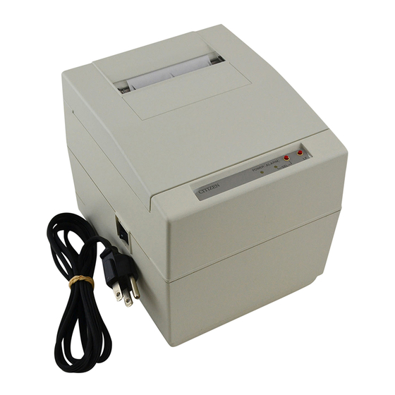
3. External Appearance and Parts Descriptions 3-1 External Appearance and Parts names Fig.1 Fig.2 CITIZEN 8/38... -
Page 9: Parts Descriptions
First press is cleared an alarm condition (ALARM RESET) and then one line print will be done by second press. 2) When the printer is in alarm state, this lamp keeps blinking at interval of 1/4 second. Remove the cause for alarm and press the SEL switch. (or re-switch the power on). - Page 10 (9) Printer Cover Open when replacing the cassette ribbon and paper. (10) Manual Paper Feed Knob Use to adjust the paper position (available only on pin tractor paper feeding model). (11) Rear Cover Cover for roll paper. (12) Stacker Basket for fan-fold paper.
-
Page 11: Preparation
User’s Manual 4. Preparation 4-1 Inserting / Removing the Printer Cover Inserting and removing the printer cover as shown in Fig. 3. Fig. 3 CITIZEN 11/38... -
Page 12: The Ribbon Cassette Installation
User’s Manual 4-2 The Ribbon Cassette Installation To insert a ribbon, disconnect the power source beforehand. When the printer has been printing for many hours, be careful not touch printer head as it might be hot. 1) Remove the printer cover 2) While inserting the ribbon into the space between the print head and the ribbon guide, press the cassette into the holder unit until it clicks into place. -
Page 13: Loading And Changing The Paper
3) Turn on the power switch and feed the paper by pushing the LF switch. 4) When the printing paper comes out of the clearance (paper cutter part) on the printer cover, fix the paper by means of paper holder, then set in on the main unit. -
Page 14: Using Fan-Fold Paper
Slide them to the appropriate position, and lock them back. 4) Hook some of the paper’s perforations on the sprockets and forward the paper into the printer mechanism by pulling and turning the paper-feed knob until the paper’s tip reaches the platen. -
Page 15: Setting / Removing The Paper Cover And Stacker
4-6 Alarm and Paper Near-End Detection This printer has the paper near-end sensor to stop the operation when the paper comes to near-end, sending out both BUSY and FAULT signals. This status is indicated by the SEL / ALARM lamp blinking at an interval of 1.0 second. -
Page 16: General Cautions
2) Replace ribbon cassette before it is worn with rents. 3) Be careful not to drop any foreign matters, such as paper clips, pins and the like into your printer. These can cause mechanical trouble. -
Page 17: Serial Interface
1. The signal for RS-232C use are based on EIA RS-232C level. 2. Please always maintain the “Mark state”, when received data is not being transferred. 3.Compatible connector (D-Sub connector) Printer side: Equivalent to AMPHENOL 17-13250 Cable side: Equivalent to AMPHENOL 17-23250 CITIZEN... -
Page 18: Input / Output Signals
5-3 Input / output Signals RS-232C Circuit Input (RD) [Printer side] [Host side] MAX232 or equivalent Output (DTR,FAULT) [Printer side] [Host side] MAX232 or equivalent : (-8V) BUSY : (+8V) READY FAULT : (-8V) Normal : (+8V) Abnormal CITIZEN 18/38... -
Page 19: Data Composition
5-4 Data Composition 1) Start bit 1/2 bit past the line dropping from MARK to SPACE, a status reading is taken again. If the reading is SPACE, a start bit is recognized. 2) Data bits and Parity bit Data bit and Parity bit are checked out every bit form the half point of start bit. Signal level of these points (Mark = 1, Space = 0) are read as input data. -
Page 20: Error Detection
The printer is designed to output DTR signals for each word. If the host computer neglects DTR signal and transmits the data, it may cause the “OVER-RUN ERROR”. In order to avoid such case, set up the host computer to observe DTR signals from the printer by following the connector pin assignments described in 5-2. -
Page 21: Parallel Interface
6. Parallel Interface 6-1 Specifications 1) Data Input System 2) Control Signal : ACK, BUSY, STB, FAULT, RESET(OPTION) 3) Compatible Connector : Printer side, Equivalent to AMPHENOL 57-40360 6-2 Connector Pin Assignment Pin No. Signal Name Data 1 Data 2... -
Page 22: Description Of Input / Output Signals
BUSY : This signal indicated that your printer is in a BUSY state. New data should be input when this signal is “LOW”. (Positive logic) FAULT : When your printer is in an alarm state, this signal is “LOW”. At this time, all control circuit of your printer are interrupted. (Negative logic) -
Page 23: Electrical Characteristics
“HIGH” Level = 2.4V Min. “LOW” Level = 0.4V Max. Input / Output Conditions All of the input signals are pulled up by 3.3K ohms. [Printer Side] 74LS373 or equivalent (7406 or equivalent only for RESET) 7406 or equivalent CITIZEN... -
Page 24: Timing Chart
6-5 Timing Chart Data Input and Print Timing T1 ……… 0.5 s Min. T2 ……… 0.5 s Min. T3 ……… 0.5 s Min. T4 ……… 270ns Max. T5 ……… 5.5 s Typ. T6 ……… 500ms Min. (When power switch is turned on) CITIZEN 24/38... -
Page 25: Dip-Switch Setting
7. Dip-Switch Setting 7-1 Dip-Switch (DS-1) Setting Function to chose SEL / DSEL State (when powered on) to chose CR code functions to chose Character Table to chose Character Table by the Country to chose output signal for external device - not used - - not used - U.S.A. -
Page 26: Dip-Switch (Ds-2) Setting
‘OLMODE’ or ON - Line Mode. In this mode, the SEL (select) switch on the operator panel is not used and the printer is always in the ‘SEL’ (selected) or ON – Line Mode. Also, the LF (linefeed) switch on the operator panel will function while the printer is this mode, even when the printer is in the ‘SEL’... -
Page 27: Dip-Switch Location
User’s Manual 7-3 Dip-Switch Location Power off and remove the printer cover before setting the Dip-Switches. CITIZEN 27/38... -
Page 28: Usage Of The Connectors (For Cash Drawers And Paper Winder)
7-4 Usage of the connectors (for cash drawers and paper winder) CN3 : connector for cash drawer and paper winder. SIGNAL DR 1 connector Printer side : 5045-04A (molex) Cable side : 5209-04 (molex) CN6 : connector for cash drawers. SIGNAL DR 1... - Page 29 Usage of the DIP switch Type Preset JP. Line JP 1 JP 2 JP 3 E type U-type *1. Do not connect External Device L1 (Drawer and Winder) to the connectors CN3-2 and CN6-2 at the same time. Note : 1) External device 1 and 2 can not be driven at the same time.
- Page 30 For U-type only (USA type) Your iDP3535 is equipped to drive up to 2 external device – Paper Winder and / or Cash Drawers. The 4 pin molex connector and the first driver of the modular connector (pins 2 & 3) are shared by the same driver and only one device can be connected to this driver.
-
Page 31: Print Control Functions
US code or line feed. Standard character designation. Carries out from feed performance after printing. Makes the printer SELECT (ON LINE) state. Only this code can be accepted irrespective of DESELECT (OFF LINE) state. Red printing is specified / released. Designation / release (alternative) of red one line printing is possible with this code. -
Page 32: Input Data Formats
When the input data become full to fill one line, the Full Buffer Print and one line feed will be automatically carried out. - Page 33 FF(0C) With this code, paper feed goes on. If there is data in the buffer when this code is input, the printer does from feed printing. The top of form for the next page is made in accordance with the page length which was specified with ESC + “C”...
-
Page 34: Initial Setting
User’s Manual 9. Initial Setting Following are automatically set after Power-on. (1) Printer head returns to its start position. (2) SELECT (ON-LINE) or DESELECT (OFF-LINE) status may be chosen by the Dip Switches for Pre-Setting. (3) Print buffer is cleared. -
Page 35: Maintenance
It is recommended that users perform periodic cleaning of their printer. (1) Exterior The exterior case of the printer can be cleaned with alcohol. Care should be taken to keep water from reaching the electronic parts and the printing mechanism. -
Page 36: Character Code Table
User’s Manual 11. Character Code Table 11-1 International Character Codes CITIZEN 36/38... -
Page 37: Individual Country Character Codes
User’s Manual 11-2 Individual Country Character Codes CITIZEN 37/38... -
Page 38: External Dimensions
User’s Manual 12. External Dimensions CITIZEN 38/38...
Need help?
Do you have a question about the iDP-3535 and is the answer not in the manual?
Questions and answers