Icom IC-78 Instruction Manual
Hf transceiver
Hide thumbs
Also See for IC-78:
- Service manualvice man (56 pages) ,
- Instruction manual (48 pages) ,
- Service manual (7 pages)
Table of Contents
Advertisement
Quick Links
Download this manual
See also:
Service Manual
INSTRUCTION MANUAL
HF TRANSCEIVER
i78
This device complies with Part 15 of the FCC rules. Operation is sub-
ject to the following two conditions: (1) This device may not cause
harmful interference, and (2) this device must accept any interference
received, including interference that may cause undesired operation.
Advertisement
Table of Contents

Subscribe to Our Youtube Channel
Related Manuals for Icom IC-78


Summary of Contents for Icom IC-78
- Page 1 INSTRUCTION MANUAL HF TRANSCEIVER This device complies with Part 15 of the FCC rules. Operation is sub- ject to the following two conditions: (1) This device may not cause harmful interference, and (2) this device must accept any interference received, including interference that may cause undesired operation.
-
Page 2: Explicit Definitions
RF output power to less than the lin- ear amplifier’s maximum input level, otherwise, the lin- ear amplifier will be damaged. Use Icom microphones only (supplied or optional). Other manufacturer’s microphones have different pin assignments, and connection to the IC-78 may dam- age the transceiver. DEFINITION... -
Page 3: Table Of Contents
IMPORTANT ... i EXPLICIT DEFINITIONS ... i PRECAUTIONS ... i 1 TABLE OF CONTENTS ... 1 SUPPLIED ACCESSORIES ... 1 2 PANEL DESCRIPTION ... 2 – 7 Front panel ... 2 Function display ... 4 Rear panel ... 5 Microphone (HM-36) ... 7 3 INSTALLATION AND CONNECTIONS ... -
Page 4: Panel Description
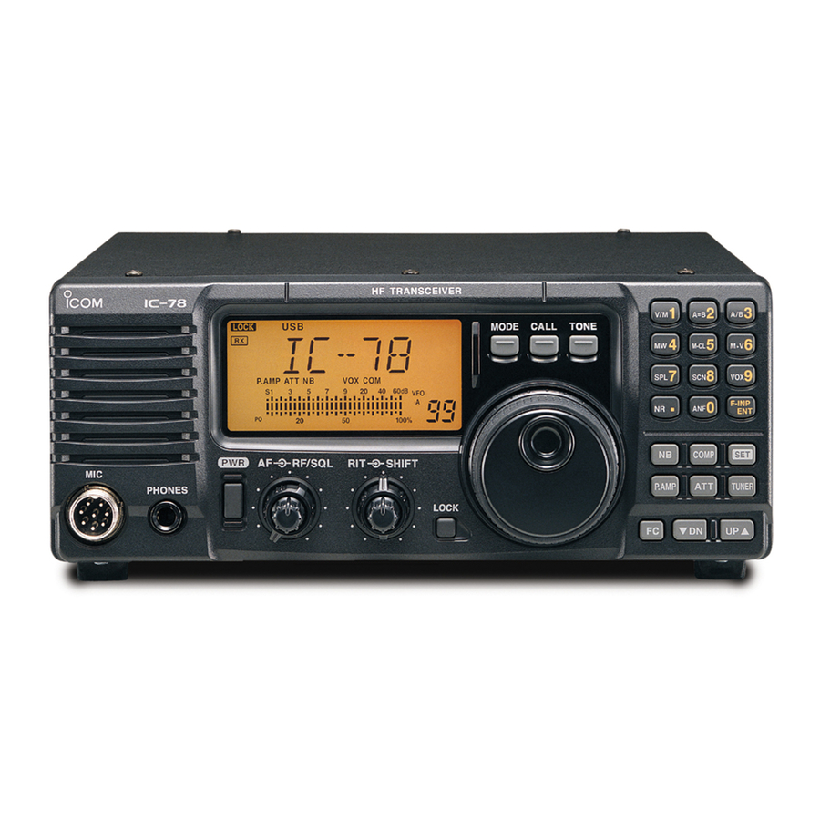
PANEL DESCRIPTION Front panel Speaker q POWER SWITCH [PWR] Push momentarily to turn power ON. • Turn the optional DC power supply ON in advance. Push for 1 sec. to turn power OFF. While pushing and holding [SET], push [PWR] to enter the initial set mode . - Page 5 !3 ATTENUATOR SWITCH [ATT] (p. 19) Push to turn the 20 dB attenuator function ON and OFF. !4 TUNER SWITCH [TUNER] (p. 18) Push to turn the antenna tuner function ON and OFF. Push for 1 sec. to manually tune the tuner. •...
-
Page 6: Function Display
PANEL DESCRIPTION Function display q LOCK INDICATOR (p. 14) Appears when the dial lock function is in use. w RECEIVE INDICATOR Appears while receiving a signal or when the squelch is open. e TUNE INDICATOR Appears or disappears when the connected au- tomatic tuner is tuned completely, depending on connected antenna tuner type. -
Page 7: Rear Panel
When connecting a paddle i ALC INPUT JACK [ALC] Connects to the ALC output jack of a non-Icom lin- ear amplifier. o SEND CONTROL JACK [SEND] Goes to ground while transmitting to control exter- nal equipment such as a linear amplifier. - Page 8 PANEL DESCRIPTION D D ACC SOCKET INFORMATION • ACC socket PIN # NAME SEND Goes to ground when transmitting. BAND Band voltage output. 9 10 11 12 1 2 3 4 13.8 V 13.8 V output when power is ON. Output current : Max. 1 A Rear panel TKEY Key line.
-
Page 9: Panel Description ................................... 2
Microphone (HM-36) • DESCRIPTION q UP/DOWN SWITCHES [UP]/[DN] Change the selected readout frequency or memory channel. • Continuous pushing changes the frequency or memory channel number continuously. • The [UP]/[DN] switch can simulate a key paddle. Preset in the CW PADDL in initial set mode. (p. 32) w PTT SWITCH Push and hold to transmit;... -
Page 10: Installation And Connections
In this case, an antenna tuner is useful to match the transceiver and antenna. Low SWR allows full power for transmitting even when using the antenna tuner. The IC-78 has an SWR meter to monitor the antenna SWR continuously. connect the [GND]... -
Page 11: Required Connections
Required connections • Front panel MICROPHONES (p. 45) HM-36 SM-20 or SM-6, SM-8 • Rear panel ANTENNA [Example]: 1.8–30 MHz bands GROUND (p. 8) Use the heaviest gauge wire or strap available and make the connection as short as possible. Grounding prevents electrical shocks, other... -
Page 12: Power Supply Connections
INSTALLATION AND CONNECTIONS Power supply connections Use an optional PS-85 DC POWER SUPPLY ing the IC-78 with AC power. Refer to the diagrams below. CONNECTING PS-85 DC POWER SUPPLY CONNECTING NON-ICOM DC POWER SUPPLY CONNECTING A VEHICLE BATTERY Grommet CAUTION: Before connecting the DC power cable, check the following important items. -
Page 13: Advanced Connections
[REMOTE] (pgs. 41, 42) Used for computer control and transceive operation, and cloning operation between transceivers. AH-2b or long wire ACC SOCKETS (p. 6) [SEND], [ALC] Used for connecting a non-Icom linear ampli- fier. EXTERNAL SPEAKER (p. 44) SP-21, etc. -
Page 14: Installation And Connections ......... 8
INSTALLATION AND CONNECTIONS External antenna tuners CONNECTING AN ANTENNA TUNER (p. 44) Long wire or optional AH-2b Coaxial cable (from the tuner) Control cable IC-78 AT-120/AT-130/AH-4 Ground Ground... -
Page 15: Operation
Selecting a channel The transceiver has 99 memory channels. However, the number of channels can be restricted in initial set mode (p. 32) depending on your needs. A total of 3 ways of channel selections are available to suit your operating style. -
Page 16: Frequency Indication
OPERATION Frequency indication By pushing the [FC], channel comment indication or frequency indication can be selected. D Transmit frequency indication By pushing the [TXF], transmit frequency is indicated, regardless channel comment or frequency indication. While transmit frequency is indicated, “ Lock function The lock function electronically locks the main dial to prevent accidental channel changing. -
Page 17: Basic Voice Receive And Transmit
[√ DN]/[UP ∫], or 10-key pad. • The S-meter shows signal strength when signal is received. Mode selection The following modes are available in the IC-78: SSB (LSB/USB), CW, CW REV (CW reverse), RTTY, RTTY REV (RTTY reverse) and AM. -
Page 18: Functions For Transmit
OPERATION Functions for transmit ï Output power and microphone gain • Setting output power q Push [SET] for 1 sec. to select quick set mode . w Push [∫ UP]/[√ DN] to select “RF POWER”. e Rotate the main dial to select the desired output. •... -
Page 19: Vox Operation
ï Microphone compressor IC-78 has a built-in, low distortion Mic compressor circuit. This circuit increases your average talk power in SSB mode and is especially useful when the re- ceiving station is having difficulty copying your signal. q Select USB or LSB mode. - Page 20 OPERATION ï Optional AT-120/AT-130/AH-4 operation The AT-120, AT-130 or AH-4 matches the IC-78 to a long wire antenna more than 7 m and above). • See p. 11 for connection. • See the connected antenna tuner’s instruction man- ual for installation and antenna connection details.
-
Page 21: Functions For Receive
Functions for receive ï RIT function The RIT (Receive Incremental Tuning) function com- pensates for off-frequencies of communicating sta- tions. The function shifts the receive frequency up to 1.2 KHz without moving the transmit frequency. q Rotate the RIT control to cancel the off-frequen- cies. - Page 22 OPERATION ï Meter peak hold The meter peak hold function freezes the highest dis- played bar segment in any meter function for about 0.5 sec. so that you can more easily read the meter. This function can be turned ON and OFF in initial set mode .
-
Page 23: Filter Selection
Filter selection The filter selection switches the IF passband width as shown in the table at right. The filter selection is for temporal setting. q Select the desired mode programmed channel. (p. 13) w Push [SET] for 1 sec. to enter quick set mode . e Push [UP Y] or [Z DN] several times until “FILTER”... -
Page 24: Filter Setting
OPERATION Filter setting When an optional filter is installed, set the optional fil- ters in initial set mode . Optional filters are not se- lected by default. (p. 33) D Optional filter setting q While pushing and holding [SET], push [PWR] to enter initial set mode . -
Page 25: Functions For Cw
Function for CW ï Connection for CW 9 10 11 12 1 2 3 4 [ELEC KEY] For no break-in operation: Connect an external switch such as [ACC] a foot switch; or use the RTTY SEND terminal for all bands. 9 10 11 (See p. -
Page 26: Electronic Cw Keyer
Push [MODE] for 1 sec. to switch between CW and CW-R modes. ï Electronic CW keyer The IC-78 has an electronic keyer. Both keying speed and weight (the ratio of dot : space : dash) can be set in quick set mode . -
Page 27: Functions For Rtty
Function for RTTY ï Connection for RTTY (FSK) Rear panel Rear panel view SQL* 9 10 11 12 AF out SEND 5 6 7 8 1 2 3 4 FSKK ï Connection for AFSK [MIC] connector (Front panel view) [ACC] connector Rear panel view SQL*... - Page 28 OPERATION ï RTTY (FSK) operation q Connect a terminal unit as at p. 25. w Select RTTY (or RTTY-R) mode with [MODE]. e Select the desired FSK tone and shift frequencies as below. r Set the desired frequency with the channel selec- tor.
-
Page 29: Channel Comment Programming
Channel comment programming The IC-78 has a capability to assign up to 8-character channel comments for each operating channel. This provides easy recognition of channel usage, or station names, etc. q Select desired channel [√ DN]/[UP ∫], rotating the channel selector, or using the keypad. -
Page 30: Set Mode
SET MODE General Set mode is used for programming infrequently changed values or conditions of functions. The IC-78 has 2 separate set modes: quick set mode and initial set mode . D Quick set mode operation q While power is ON, push [SET] for 1 sec. -
Page 31: Quick Set Mode Items
SET MODE Quick set mode items • RF power This item adjusts the RF output power. The RF output power can be adjusted from L, 1 to 99 and H by indication, however, it can be adjusted continuously. •The default is H (maximum power). Note that while adjusting the output power, the power meter is displayed auto- matically. - Page 32 SET MODE Quick set mode items — (continued) • BK-IN This item selects break-in type for CW operation. There are three selectable values: oF : No break-in operation available (default). SE : Semi break-in operation available. FL : Full break-in operation available •...
-
Page 33: Initial Set Mode Items
Initial set mode items • RF/SQL control action Select [RF/SQL] control action from RF/squelch, automatic (acts as squelch in AM modes; as RF in SSB/CW/RTTY modes), or the squelch. The default is Sq (squelch). • Beep A beep sounds each time a switch is pushed to confirm it. This function can be turned OFF for silent operation. - Page 34 The IC-78’s address is 62. When 2 or more IC-78s are connected to an optional CT-17 , rotate the main dial to select a different address for each IC-78 in the VERTER range 01H to 7FH.
- Page 35 SET MODE Initial set mode items — (continued) • OPTION Filter When an optional IF filer is installed, this selection is necessary, otherwise the filters cannot be selected. Selections available are FL-96, FL-222, FL-52A, FL- 53A, FL-257 and none (default). See p. 21 for usable filters for each mode and see p.
-
Page 36: Extra Features
EXTRA FEATURES INTRODUCTION Extra features, explained in this section, are available only on some versions of the IC-78. Therefore, the instructions in this section are not necessary for some versions. VFO operation D Entering VFO mode To enter VFO mode, push [FC] for 1 sec. -
Page 37: Channel Programming
D Channel programming The programmed frequencies, both transmit and re- ceive, in operating channel can be re-programmed from the VFO mode. • Simplex channel programming q Push [FC] for 1 sec. to enter VFO mode. w Push [√ DN]/[UP ∫] to select the desired channel. •... -
Page 38: 2-Tone Alarm Operation
EXTRA FEATURES D Channel clearing If un-necessary channels are available, the stored fre- quency can be cleared. The cleared channels are skipped in the channel mode operation, q Select desired channel in channel mode. (p. 13) w Enter VFO mode by pushing [FC] for 1 sec. •... -
Page 39: Dc Power Cable
CAUTION: DISCONNECT the DC power cable from the IC-78 before performing any work on the transceiver. Otherwise, there is danger of electric shock and/or equipment damage. q Remove the 5 screws from the top of the trans- ceiver and 4 screws from the sides, then lift up the top cover. -
Page 40: Cr-338 High Stability Crystal Unit
64.00000 MHz with C 16.) Optional IF filters Several IF filters are available for the IC-78. You can install 1 filter for 455 KHz IF. Choose the appropriate filter for your operating needs. (pgs, 21, 22) D Installation q Remove the bottom cover as shown on the p. -
Page 41: Maintenance
MAINTENANCE If you are not able to locate the cause of a problem or solve it through the use of this chart, contact your near- est Icom Dealer or Service Center. POSSIBLE CAUSE • Re-connect the DC power cable correctly. -
Page 42: Fuse Replacement
CAUTION: DISCONNECT the DC power cable from the transceiver when changing a fuse. The IC-78 has 2 types of fuses installed for transceiver protection. • DC power cable fuses ... FGB 20 A • Circuitry fuse ... FGB 4 A CIRCUITRY FUSE REPLACEMENT The 13.8 V DC from the DC power cable is applied to... -
Page 43: Remote Jack Information
RS-232C port. The Icom Communi- cations Interface-V (CI-V) controls the following func- tions of the transceiver. Up to 4 Icom CI-V transceivers or receivers can be connected to a personal computer equipped with an RS-232C port. See p. 32 for setting the CI-V condition using set mode. -
Page 44: Data Cloning Between Transceivers
• Data cloning The IC-78’s data (programmed frequencies, channel comment, both quick and initial set mode conditions, etc.) can be copied to the other IC-78. This function is useful when exactly the same setting of the IC-78s is required. • Cloning operation q Turn power OFF. -
Page 45: Specifications
GENERAL • Frequency range 0.030000–29.999999 MHz* 1.600000–29.999999 MHz* Guaranteed range: 0.5–29.999999 MHz Not guaranteed for some frequency bands • Mode : USB, LSB, CW, RTTY, AM • No. of memory channels : 99 • Frequency stability Less than ±200 Hz from 1 min. to 60 min. after power ON. -
Page 46: Options
OPTIONS PS-85 DC POWER SUPPLY Light weight switching regulator sys- tem power supply. • Output voltage: 13.8 V DC • Max. current drain: 20 A AH-2b ANTENNA ELEMENT A 2.5 m long an- tenna element for mobile operation with the AH-4. •... - Page 47 SM-6 DESKTOP MICROPHONE Electret condenser-type desktop mi- crophone. HM-36 HAND MICROPHONE Hand microphone equipped with [UP]/[DOWN] switches. Same as supplied. CT-17 CI-V LEVEL CONVERTER For remote transceiver control using a personal computer. You can change frequencies, operating mode, memory channels, etc. OPC-420 4-CONDUCTOR SHIELD CABLE For the connection between transceiver and antenna tuner.
- Page 48 A-5658H-1EX-w Printed in Japan 1-1-32 Kamiminami, Hirano-ku, Osaka 547-0003 Japan © 2000 Icom Inc.
Need help?
Do you have a question about the IC-78 and is the answer not in the manual?
Questions and answers