Advertisement
Quick Links
Advertisement

Related Manuals for ENTRYPASS EP.MINI


Summary of Contents for ENTRYPASS EP.MINI
- Page 1 Wiring Guide EP.MINI Version 1.00 Last Updated: 09-01-2010 ENTRYPASS...
- Page 2 There are currently 2 version of EntryPass Platform1 Access Control System available for different card number system 1) EntryPass Platform1 Access Control System (6 Digit Card Number System) cater for 6 digit card number installation 2)EntryPass Platform1 Access Control System (10 Digit Card Number System) cater for 10 digit card...
-
Page 3: Before You Begin
Model: EP.MINI Before you begin Technical Support If you cannot find the answer to your question in this manual or in the Help files, we recommend you contact your system installer. Your installer is familiar with your system configuration and should be able to answer any of your questions. -
Page 4: Considerations Prior To Installation
Considerations Prior to Installation Preparing Your EntryPass Controllers EntryPass controller contains numerous delicate electronic circuits and components which can become damaged as a result of electrostatic discharge (ESD). Thus, prior to installation, please follow the instruction below: •Observe precautions while handling the circuit board assembly by using proper grounding straps and handling precautions at all •Visually ensure no onboard parts is broken, damage or contains burn mark... - Page 5 Model: EP.MINI MiNi Description Encrypted Lock Control MiNi Reader (ELC) Keypad Display Unit ENTRYPASS...
- Page 6 Model: EP.MINI MiNi Color Description Encrypted Lock Control (ELC) Description MiNi Reader Color Description : +12VDC : +12VDC Black : GND / 0VDC Black : GND / 0VDC Orange : RCLK Pink : Door Sensor Yellow : RDAT Black : GND / 0VDC...
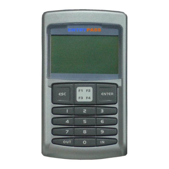
- Page 7 Model: EP.MINI MiNi reader keypad display unit White LCD Display Navigation Pad Enter Key Numbered Keypad LED Indicator ENTRYPASS...
- Page 8 Model: EP.MINI Power Supply Unit Specification ENTRYPASS Power Supply Unit Specification: • Switching Power Supply • 12V DC • 3 Amp (Minimum) ENTRYPASS...
- Page 9 Model: EP.MINI Connecting MINI to ELC Switching Mode Power Supply Unit (12V DC, 3A Minimum) +12 VDC Black (Gnd) Black (Gnd) Red (+12VDC) Red (+12VDC) Blue (RTX) Blue (RTX) Orange (RCLK) Orange (RCLK) Yellow (RDAT) Yellow (RDAT) The distance from MINI keypad reader to ELC should not more than 10 meter...
- Page 10 Model: EP.MINI Connecting the Lock (NC), Breakglass and Keyswitch to ELC Switching Mode Power Supply Unit (12V DC, 3A Minimum) White/Blue (CM1) White (NC1) Purple (+12VDC) Purple (+12VDC) Emergency Breakglass Emergency Keyswitch Electro-Magnetic Lock Diode(1N4002) must be installed at the locking devices in order to protect against back EMF...
- Page 11 Model: EP.MINI Connecting the Lock (NO) Switching Mode Power Supply Unit (12V DC, 3A Minimum) White/Blue (CM1) Grey/Yellow (NO1) Purple (+12VDC) Purple (+12VDC) Electro-Magnetic Lock (Drop Bolt) Diode(1N4002) must be installed at the locking devices in order to protect against back EMF...
- Page 12 Model: EP.MINI Connecting the Door Sensor and Door Release Button/Push Button Pink (Door Sensor) Pink (Push Button) Black (Gnd) Black (Gnd) Door Sensor Push Button The distance from door sensor to MINI and from push button to ELC should not more than 30 meter...
- Page 13 Model: EP.MINI Connecting the Exit Reader – MINI reader as an exit reader To configure MINI as a READER Mode, press: Switching Mode •F1 Power Supply Unit •123456 (12V DC, 3A Minimum) •01 Enter •01 Enter +12 VDC •05 Enter •1 Enter...
- Page 14 Model: EP.MINI Connecting the Exit Reader – 3 Party Reader Switching Mode Power Supply Unit (12V DC, 3A Minimum) +12 VDC Black (Gnd) Black (Gnd) Red (+12VDC) Red (+12VDC) Green (D0) Green (D0) White (D1) White (D1) Exit Reader The distance from MINI to exit reader should not more than 10 meter...
- Page 15 255.255.255.5 255.255.255.6 255.255.255.7 The unit address that you configure on the MINI 255.255.255.8 controller will determine the controller address on the 255.255.255.9 EntryPass Platform1 Access Control System software 255.255.255.10 255.255.255.11 To configure MINI unit address 255.255.255.12 (default: 00), press: •F1 255.255.255.13...
- Page 16 Model: EP.MINI Connecting to the PC using RS 232 mode DB 9 Female Connecter White to Pin 2 Black (Gnd) Green to Pin 3 Black to Pin 5 Green (RS 232 RX) White (RS 232 TX) EntryPass Platform1 Server Access...
- Page 17 Model: EP.MINI Connecting to the PC using RS 485 mode MINI 16 MINI 2 MINI 1 Unit Address: 15 Unit Address: 01 Unit Address: 00 Grey (C+) Grey (C+) Grey (C+) Purple (C-) Purple (C-) Purple (C-) To configure MINI unit address (default: 00), press: •F1...
- Page 18 Model: EP.MINI Connecting to the power supply unit Switching Mode Power Supply Unit (12V DC, 3A Minimum) +12 VDC Red/Yellow (+12VDC) Black (Gnd) ENTRYPASS...
-
Page 19: Complete Overview
Model: EP.MINI Complete overview Switching Mode Power Supply Unit (12V DC, 3A Minimum) +12 VDC Red/Yellow (+12VDC) Black (Gnd) Black (Gnd) Orange (RCLK) Orange (RCLK) Yellow (RDAT) Yellow (RDAT) Blue (RTX) Blue (RTX) Red (+12VDC) Pink (Push Button) Green (D0) - Page 20 Before connecting to the EntryPass Platform1 Access Control System Before you begin to connect to the EntryPass Platform1 Access Control System, please make sure all the wiring connection is correct. On the MINI keypad, please make sure the following setting...
- Page 21 •0 Enter (Press 1 to set it ON or press 0 to set it OFF) •02 Enter Advisable to •ESC X3 •ESC X3 •07 Enter EP.MINI unit address perform format •Key in the new door pin (6 digits) if there is more than Security Level Site Code 1 •10 Enter...
- Page 22 •ESC X3 Format Memory To configure the •Enter programming mode Advisable to Exit Button Tz Card+Pin Tz •01 Enter EP.MINI unit address •Enter programming mode •Enter programming mode •05 Enter perform format •01 Enter •01 Enter •03 Enter if there is more than memory for the •02 Enter...
- Page 23 •Flash all the cards to be installed (card by card) •ESC X3 •ESC X4 To configure the Transaction Advisable to Quick Delete •Enter programming mode EP.MINI unit address •Enter programming mode •02 Enter perform format •02 Enter if there is more than •02 Enter memory for the •01 Enter...
- Page 24 To configure the Security Level •Key in the new door pin timezone Advisable to •Enter programming mode Door Pin 1 •ESC X3 EP.MINI unit address •01 Enter •Enter programming mode perform format if there is more than •01 Enter •01 Enter...
- Page 25 Release Time •Enter programming mode Delete Card Advisable to •Enter programming mode •01 Enter •Enter programming mode EP.MINI unit address •01 Enter •04 Enter •02 Enter perform format •02 Enter •Key in the new time (HHMMSS) if there is more than •01 Enter...
- Page 26 •Key in the card number that need to perform pin reset (10 digits) •ESC X3 To configure the Advisable to Reset Lockout EP.MINI unit address •Enter programming mode perform format •02 Enter if there is more than memory for the •01 Enter...
-
Page 27: Cabling Information
(30 ft) To configure the Advisable to PC Communicator to RS 485 1000m 22 AWG, 2 Pairs, Shielded EP.MINI unit address perform format MINI (3000 ft) if there is more than memory for the 1 MINI controller MINI to exit reader...
Need help?
Do you have a question about the EP.MINI and is the answer not in the manual?
Questions and answers