
Subscribe to Our Youtube Channel
Related Manuals for ENTRYPASS EP.S3150


Summary of Contents for ENTRYPASS EP.S3150
- Page 1 HCB WIRING GUIDE EP.S3150 EP.N5150 EP.S3200 EP.N5200 EP.S3400 EP.N5400 Version: 1.18 Last Updated: 18-07-2018 ENTRYPASS TECHNICAL – WIRING GUIDE Copyright © Entrypass Corporation...
- Page 2 For existing site, P1 will detect its card database to determine 6 or 10 digits; For new site, user can change the digits as long as the card database is empty Please refer to separate EntryPass Platform1 User Manual for detail operation help. The Official EntryPass Platform1 User Manual can be downloaded from our website under “Download”...
- Page 3 Should you need additional information, please call our Technical Support Help desk, Monday to Friday 9:00 AM to 6:00 PM (GMT +8:00) Method Details Phone + 60 (3) - 8068 1929 Fax + 60 (3) - 8068 1922 Internet www.entrypass.net Email support@entrypass.net ENTRYPASS TECHNICAL – WIRING GUIDE Copyright © Entrypass Corporation...
- Page 4 Considerations Prior to Installation Preparing Your EntryPass Controllers EntryPass controller contains numerous delicate electronic circuits and components which can become damaged as a result of electrostatic discharge (ESD). Thus, prior to installation, please follow the instruction below: •Observe precautions while handling the circuit board assembly by using proper grounding straps and handling precautions at all •Visually ensure no onboard parts is broken, damage or contains burn mark...
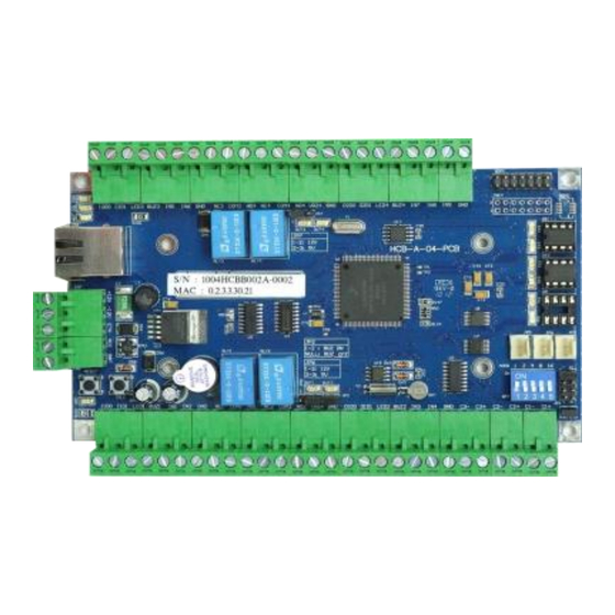
- Page 5 Cold Start, Switch Factory Default and AES Heartbeat Hard reset Selection Jumper Cold Address Start Switch Buzzer Relay Relay Supply Buzzer Relay MCU Battery RS485 Switch Voltage ON/OFF LEDs COMs Selector ENTRYPASS TECHNICAL – WIRING GUIDE Copyright © Entrypass Corporation...
- Page 6 - Supply Voltage Ground Connection For VR1+ to supply 12V, please make sure JP6 is at 1-2 pins For VR1+ to supply 5V, please make sure JP6 is at 2-3 pins ENTRYPASS TECHNICAL – WIRING GUIDE Copyright © Entrypass Corporation...
- Page 7 - Relay 4 Normally Open Connection For VR2+ to supply 12V, please make sure JP7 is at 1-2 pins For VR2+ to supply 5V, please make sure JP7 is at 2-3 pins ENTRYPASS TECHNICAL – WIRING GUIDE Copyright © Entrypass Corporation...
- Page 8 BAT/BS (Backup Battery Monitoring) point will monitor the backup battery voltage which will supply power to the board when AC power is cut off The minimum voltage for cutoff while using backup battery is 10.8V ENTRYPASS TECHNICAL – WIRING GUIDE Copyright © Entrypass Corporation...
- Page 9 Power Supply Unit Specification ENTRYPASS Power Supply Unit Specification: • Switching Power Supply • 12V DC • 3 Amp (Minimum) ENTRYPASS TECHNICAL – WIRING GUIDE Copyright © Entrypass Corporation...
- Page 10 Electro-Magnetic Lock or Drop Bolt Diode(1N4002) must be installed at the locking devices in order to protect against back EMF. It is advisable to connect EM lock COM to +12Vof PSU (Power Supply Unit) ENTRYPASS TECHNICAL – WIRING GUIDE Copyright © Entrypass Corporation...
- Page 11 NC1 COM1 NO1 COM2 VR1+ GND O1D0 O1D1 LED2 BUZ2 COM1 +12V – Striker Lock or Drop Bolt Diode(1N4002) must be installed at the locking devices in order to protect against back EMF ENTRYPASS TECHNICAL – WIRING GUIDE Copyright © Entrypass Corporation...
- Page 12 Breakglass 2 Keyswitch 2 Electro-Magnetic Lock 2 Emergency Emergency Breakglass 1 Keyswitch 1 Electro-Magnetic Lock 1 Diode(1N4002) must be installed at the locking devices in order to protect against back EMF ENTRYPASS TECHNICAL – WIRING GUIDE Copyright © Entrypass Corporation...
- Page 13 GND O1D0 O1D1 LED2 BUZ2 +12V Striker Lock or Drop Bolt 2 Striker Lock or Drop Bolt 1 Diode(1N4002) must be installed at the locking devices in order to protect against back EMF ENTRYPASS TECHNICAL – WIRING GUIDE Copyright © Entrypass Corporation...
- Page 14 Diode(1N4002) must be installed at the locking devices in order to protect against back EMF NC1 and NC2 connection for 4 Doors Mode, please refer to 2 Doors Mode NC connection 4 Doors Mode only applicable for N5400 and S3400 ENTRYPASS TECHNICAL – WIRING GUIDE Copyright © Entrypass Corporation...
- Page 15 Diode(1N4002) must be installed at the locking devices in order to protect against back EMF NO1 and NO2 connection for 4 Doors Mode, please refer to 2 Doors Mode NO connection 4 Doors Mode only applicable for N5400 and S3400 ENTRYPASS TECHNICAL – WIRING GUIDE Copyright © Entrypass Corporation...
- Page 16 Connecting the Door Sensor and Push Button Lower Connector I1D0 I1D1 LED1 BUZ1 NC1 COM1 NO1 COM2 VR1+ GND O1D0 O1D1 LED2 BUZ2 Door Sensor Push Button ENTRYPASS TECHNICAL – WIRING GUIDE Copyright © Entrypass Corporation...
- Page 17 (2 Doors Mode) Lower Connector I1D0 I1D1 LED1 BUZ1 NC1 COM1 NO1 COM2 VR1+ GND O1D0 O1D1 LED2 BUZ2 Door Sensor 1 Door Sensor 2 Push Button 1 Push Button 2 ENTRYPASS TECHNICAL – WIRING GUIDE Copyright © Entrypass Corporation...
- Page 18 VR2+ GND O2D0 O2D1 LED4 BUZ4 Upper Connection IN1,2,3,4 Connections for 4 Doors Mode please refer to 2 Doors Mode IN1,2,3,4 connections 4 Doors Mode only applicable for N5400 and S3400 ENTRYPASS TECHNICAL – WIRING GUIDE Copyright © Entrypass Corporation...
- Page 19 VR2+ GND O2D0 O2D1 LED4 BUZ4 Upper Connection Lower Connector I1D0 I1D1 LED1 BUZ1 NC1 COM1 NO1 COM2 VR1+ GND O1D0 O1D1 LED2 BUZ2 Reader 3 and Reader 4 only applicable for N5400 and S3400 ENTRYPASS TECHNICAL – WIRING GUIDE Copyright © Entrypass Corporation...
- Page 20 Power Supply Unit Power Supply Unit (12VDC, 1A) (12VDC, 1A) GND (Black) Cat 5e Network Switch Each of the Suprema device require power of 12VDC, 500mA ~ 1A depend on the model ENTRYPASS TECHNICAL – WIRING GUIDE Copyright © Entrypass Corporation...
- Page 21 Connecting the Reader – Entrypass BR100 Devices Lower Connector I1D0 I1D1 LED1 BUZ1 NC1 COM1 NO1 COM2 VR1+ GND O1D0 O1D1 LED2 BUZ2 Wiegand GND (Black) +12V (Red) Power Supply Unit Power Supply Unit (12VDC, 1A) (12VDC, 1A) GND (Black)
- Page 22 Please configure the interlock input as ‘Open Trigger’ in Platform1 Server, if interlock input is connected with NC relay output. Advisable to use analog input for detecting line open condition The cabling distance for cross-board interlock connection can up to 100 meter ENTRYPASS TECHNICAL – WIRING GUIDE Copyright © Entrypass Corporation...
- Page 23 RS-232: 10 meter (Communicator) EntryPass Platform1 Access Control System Serial connection (RS485) only applicable for maximum 16 sets S3150/S3200/S3400 The serial address format in Platform1 is 255.255.255.X where X is unit address ENTRYPASS TECHNICAL – WIRING GUIDE Copyright © Entrypass Corporation...
- Page 24 Unit Address: 1 Serial Port DB9 Female Connector RS-232: 10 meter EntryPass Platform1 Access Control System Serial connection (RS232) only applicable for a single S3150/S3200/S3400 The serial address format in Platform1 is 255.255.255.1 ENTRYPASS TECHNICAL – WIRING GUIDE Copyright © Entrypass Corporation...
- Page 25 The number in ( ) is the address of each individual switch of the dip switch Example: To obtain Address 11, 1 + 2 + 8 = 11, So just switch on switch 1, 2, 4 ENTRYPASS TECHNICAL – WIRING GUIDE Copyright © Entrypass Corporation...
- Page 26 N5150/N5200/N5400 (n) …. Cat-5e …. Network Switch EntryPass Platform1 Server Access Control System Network connection only applicable for N5150, N5200 and N5400 Factory default IP address for network controller is 192.168.1.100 ENTRYPASS TECHNICAL – WIRING GUIDE Copyright © Entrypass Corporation...
- Page 27 Connecting to Power Supply Unit Switching Mode Power Supply Unit (12V DC, 3A Minimum) +12V AC Fail (ACC) Backup Battery Monitoring (BAT/BS) ENTRYPASS TECHNICAL – WIRING GUIDE Copyright © Entrypass Corporation...
- Page 28 4. Release COLD switches when a long beeping sound heard Advisable to perform cold start for the first time you turn on the power The buzzer will only beep if jumper is placed on (JP2) 1-2 ENTRYPASS TECHNICAL – WIRING GUIDE Copyright © Entrypass Corporation...
- Page 29 Factory Default will change the IP Address back to 192.168.1.100, Server IP to 192.168.1.254 and Port to 2020 For the network controller support AES Encryption feature, factory default will disable the AES feature ENTRYPASS TECHNICAL – WIRING GUIDE Copyright © Entrypass Corporation...
- Page 30 2. Press RESET Switch and Release RESET switch AES setting in the controller will be reset If the controller is connected with AES enabled Platfrom1, Platfrom1 will sync and update AES setting with the controller ENTRYPASS TECHNICAL – WIRING GUIDE Copyright © Entrypass Corporation...
- Page 31 The Inputs are configurable to digital (default) or analog using Platform1 A resistor of 3600 ohm is required when using analog input This system is not support NO Analog device due to the architecture ENTRYPASS TECHNICAL – WIRING GUIDE Copyright © Entrypass Corporation...
- Page 32 Exit Reader +12V -12V Serial Controller – S3150, S3200, S3400 Network Controller – N5150, N5200, N5400 Emergency Emergency Breakglass Keyswitch ENTRYPASS Electro-magnetic Lock Platform1 Profile: In and Out Readers Power Supply Unit ENTRYPASS TECHNICAL – WIRING GUIDE Copyright © Entrypass Corporation...
- Page 33 Network Controller – N5150, N5200, N5400 Breakglass 2 Keyswitch 2 +12V -12V Electro-magnetic Lock 2 Emergency Emergency Keyswitch 1 Breakglass 1 ENTRYPASS Electro-magnetic Lock 1 Platform1 Profile: 2 Doors Power Supply Unit ENTRYPASS TECHNICAL – WIRING GUIDE Copyright © Entrypass Corporation...
- Page 34 Network Switch RS 232 Door Sensor 1 & Exit Button 1 Reader 1 Reader 2 EntryPass Platform1 Access Control System Electro-magnetic Lock 1 Platform1 Profile: 2 x In and Out Doors ENTRYPASS TECHNICAL – WIRING GUIDE Copyright © Entrypass Corporation...
- Page 35 Door Sensor 2 Door Sensor 1 & & Exit Button 2 Electro-magnetic Exit Button 1 Lock 2 Reader 1 Reader 2 EntryPass Platform1 Access Control System Electro-magnetic Lock 1 Platform1 Profile: 4 Doors ENTRYPASS TECHNICAL – WIRING GUIDE Copyright © Entrypass Corporation...
- Page 36 +12V -12V Access Control System Exit Barrier Serial Controller – S3150, S3200, S3400 Network Controller – N5150, N5200, N5400 ENTRYPASS Entry Barrier Power Supply Unit Platform1 Profile: In and Out Barriers ENTRYPASS TECHNICAL – WIRING GUIDE Copyright © Entrypass Corporation...
- Page 37 Network Loop Detector 1 Switch RS 232 Entry Reader Exit Reader 1 Entry Barrier 1 Exit Barrier 1 EntryPass Platform1 Access Control System ENTRYPASS TECHNICAL – WIRING GUIDE Platform1 Profile: 2 x In and Out Barriers Copyright © Entrypass Corporation...
- Page 38 EntryPass +12V -12V Platform1 Access Control System Serial Controller – S3150, S3200, S3400 Network Controller – N5150, N5200, N5400 ENTRYPASS Bidirectional Turnstile Platform1 Profile: In and Out Turnstile Power Supply Unit ENTRYPASS TECHNICAL – WIRING GUIDE Copyright © Entrypass Corporation...
- Page 39 Exit Reader Entry Reader EntryPass +12V -12V Platform1 Access Control System Serial Controller – S3150, S3200, S3400 Network Controller – N5150, N5200, N5400 ENTRYPASS Power Supply Unit Platform1 Profile: 2 Turnstile Mode ENTRYPASS TECHNICAL – WIRING GUIDE Copyright © Entrypass Corporation...
- Page 40 Controller Only Power Network Switch RS232 Entry Rea der 1 Exit R eader 1 Bidirectiona l Turnstile 1 EntryPass Platform1 Access Control System Platform1 Profile: 2 x In and Out Turnstiles ENTRYPASS TECHNICAL – WIRING GUIDE Copyright © Entrypass Corporation...
- Page 41 GND O1D0 O1D1 LED2 BUZ2 Network Port For Network Controller Only Power Network Switch RS232 Reader 1 Reader 2 Turnstile 1 Turnstile 2 EntryPass Platform1 Access Control System Platform1 Profile: 4 Turnstiles ENTRYPASS TECHNICAL – WIRING GUIDE Copyright © Entrypass Corporation...
- Page 42 22 AWG, 1 Pair Sensor (100 ft) Controller to Controller 100m for Cross-Board Contact 22 AWG, 1 Pair (300 ft) Interlock Serial Controller – S3150, S3200, S3400 Network Controller – N5150, N5200, N5400 ENTRYPASS TECHNICAL – WIRING GUIDE Copyright © Entrypass Corporation...
Need help?
Do you have a question about the EP.S3150 and is the answer not in the manual?
Questions and answers