
Related Manuals for ENTRYPASS EP.MINI


Summary of Contents for ENTRYPASS EP.MINI
- Page 1 EP.MINI WIRING GUIDE Version: 1.01 Last Updated: 21-06-2016 ENTRYPASS TECHNICAL – WIRING GUIDE Copyright © Entrypass Corporation...
- Page 2 There are currently 2 version of EntryPass Platform1 Access Control System available for different card number system 1) EntryPass Platform1 Access Control System (6 Digit Card Number System) cater for 6 digit card number installation 2) EntryPass Platform1 Access Control System (10 Digit Card Number System) cater for 10...
- Page 3 Should you need additional information, please call our Technical Support Help desk, Monday to Friday 9:00 AM to 6:00 PM (GMT +8:00) Method Details Phone + 60 (3) - 8068 1929 Fax + 60 (3) - 8068 1922 Internet www.entrypass.net Email support@entrypass.net ENTRYPASS TECHNICAL – WIRING GUIDE Copyright © Entrypass Corporation...
- Page 4 Considerations Prior to Installation Preparing Your EntryPass Controllers EntryPass controller contains numerous delicate electronic circuits and components which can become damaged as a result of electrostatic discharge (ESD). Thus, prior to installation, please follow the instruction below: •Observe precautions while handling the circuit board assembly by using proper grounding straps and handling precautions at all •Visually ensure no onboard parts is broken, damage or contains burn mark...
- Page 5 MINI Description Encrypted Lock Control MINI Reader (ELC) Keypad Display Unit ENTRYPASS TECHNICAL – WIRING GUIDE Copyright © Entrypass Corporation...
- Page 6 Purple : RS485 C- Brown : NO2 Grey : CM2 Green : RS232 RX Separated Green : NC2 White : RS232 TX Separated Purple : +12V DC Lock Purple : +12V DC Lock ENTRYPASS TECHNICAL – WIRING GUIDE Copyright © Entrypass Corporation...
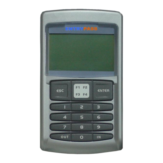
- Page 7 MINI Reader Keypad Display Unit White LCD Display Navigation Pad Enter Key Numbered Keypad LED Indicator ENTRYPASS TECHNICAL – WIRING GUIDE Copyright © Entrypass Corporation...
- Page 8 Power Supply Unit Specification ENTRYPASS Power Supply Unit Specification: • Switching Power Supply • 12V DC • 3 Amp (Minimum) ENTRYPASS TECHNICAL – WIRING GUIDE Copyright © Entrypass Corporation...
- Page 9 Black (Gnd) Red (+12VDC) Red (+12VDC) Blue (RTX) Blue (RTX) Orange (RCLK) Orange (RCLK) Yellow (RDAT) Yellow (RDAT) The distance from MINI keypad reader to ELC should not more than 10 meter ENTRYPASS TECHNICAL – WIRING GUIDE Copyright © Entrypass Corporation...
- Page 10 (12V DC, 3A Minimum) White/Blue (CM1) White (NC1) Purple (+12VDC) Purple (+12VDC) Emergency Breakglass Emergency Keyswitch Electro-Magnetic Lock Diode(1N4002) must be installed at the locking devices in order to protect against back EMF ENTRYPASS TECHNICAL – WIRING GUIDE Copyright © Entrypass Corporation...
- Page 11 (12V DC, 3A Minimum) White/Blue (CM1) Grey/Yellow (NO1) Purple (+12VDC) Purple (+12VDC) Electro-Magnetic Lock (Drop Bolt) Diode(1N4002) must be installed at the locking devices in order to protect against back EMF ENTRYPASS TECHNICAL – WIRING GUIDE Copyright © Entrypass Corporation...
- Page 12 Pink (Door Sensor) Pink (Push Button) Black (Gnd) Black (Gnd) Door Sensor Push Button The distance from door sensor to MINI and from push button to ELC should not more than 30 meter ENTRYPASS TECHNICAL – WIRING GUIDE Copyright © Entrypass Corporation...
- Page 13 • 01 Enter • 04 Enter Exit Reader • 1 Enter • ESC x3 To use MINI/N-MINI on exit reader side, you must enable the READER MODE function on the programming mode ENTRYPASS TECHNICAL – WIRING GUIDE Copyright © Entrypass Corporation...
- Page 14 Black (Gnd) Black (Gnd) Red (+12VDC) Red (+12VDC) Green (D0) Green (D0) White (D1) White (D1) Exit Reader The distance from MINI to exit reader should not more than 10 meter ENTRYPASS TECHNICAL – WIRING GUIDE Copyright © Entrypass Corporation...
- Page 15 255.255.255.8 255.255.255.9 255.255.255.10 255.255.255.11 The unit address that you configure on the MINI controller will determine the controller address on the 255.255.255.12 EntryPass Platform1 Access Control System software 255.255.255.13 255.255.255.14 255.255.255.15 ENTRYPASS TECHNICAL – WIRING GUIDE Copyright © Entrypass Corporation...
- Page 16 Green to Pin 3 Black to Pin 5 Green (RS 232 RX) White (RS 232 TX) EntryPass Platform1 Server Access Control System The distance from computer to MINI should not more than 10 meter ENTRYPASS TECHNICAL – WIRING GUIDE Copyright © Entrypass Corporation...
- Page 17 When the implementation consists of more than 1 MINI to be connected to the PC using the same bus/comport, the unit address for each MINI must be unique. Only a total of 16 controllers can be connected to each bus/comport. ENTRYPASS TECHNICAL – WIRING GUIDE Copyright © Entrypass Corporation...
- Page 18 Connecting to Power Supply Unit Switching Mode Power Supply Unit (12V DC, 3A Minimum) +12 VDC Red/Yellow (+12VDC) Black (Gnd) ENTRYPASS TECHNICAL – WIRING GUIDE Copyright © Entrypass Corporation...
- Page 19 Pink (Door Sensor) White (NC1) Purple (+12VDC) Grey (C+) Purple (C-) Emergency Breakglass Emergency Keyswitch Push Button Door Sensor Exit Reader EntryPass Platform1 (Pc Communicator) Server Access Control System ENTRYPASS TECHNICAL – WIRING GUIDE Electro-Magnetic Lock Copyright © Entrypass Corporation...
- Page 20 Before Connecting to the EntryPass Platform1 Access Control System Before you begin to connect to the EntryPass Platform1 Access Control System, please make sure all the wiring connection is correct. On the MINI keypad, please make sure the following setting has been done:...
- Page 21 •02 Enter •04 Enter •06 Enter •Key in the new unit address (00 - 15 sets) •Key in the new door pin (6 digits) •ESC X3 •09 Enter •01 •ESC X3 ENTRYPASS TECHNICAL – WIRING GUIDE Copyright © Entrypass Corporation...
- Page 22 •13 Enter •Enter programming mode •Key in the new auto release time zone •01 Enter •ESC X3 •02 Enter •09 Enter •Key in the new door pin time zone •ESC X3 ENTRYPASS TECHNICAL – WIRING GUIDE Copyright © Entrypass Corporation...
- Page 23 •Enter programming mode •03 Enter •01 Enter •When finish formatting, a beep sound will be heard •02 Enter •ESC X2 •16 Enter •Key in the new pin trials (00 – 09) •ESC X3 ENTRYPASS TECHNICAL – WIRING GUIDE Copyright © Entrypass Corporation...
- Page 24 Info Menu •Enter programming mode Quick Install •03 Enter •Enter programming mode •ESC X2 •02 Enter •01 Enter •04 Enter •Flash all the cards to be installed (card by card) •ESC X4 ENTRYPASS TECHNICAL – WIRING GUIDE Copyright © Entrypass Corporation...
- Page 25 •02 Enter •04 Enter •03 Enter •Key in the new unit address (00 - 15 sets) •Key in the new door pin (6 digits) •ESC X3 •06 Enter •01 •ESC X3 ENTRYPASS TECHNICAL – WIRING GUIDE Copyright © Entrypass Corporation...
- Page 26 •10 Enter •Enter programming mode •Key in the new auto release time zone •01 Enter •ESC X3 •02 Enter •06 Enter •Key in the new door pin time zone •ESC X3 ENTRYPASS TECHNICAL – WIRING GUIDE Copyright © Entrypass Corporation...
- Page 27 •Enter programming mode •03 Enter •01 Enter •When finish formatting, a beep sound will be heard •02 Enter •ESC X2 •13 Enter •Key in the new pin trials (00 – 09) •ESC X3 ENTRYPASS TECHNICAL – WIRING GUIDE Copyright © Entrypass Corporation...
- Page 28 Info Menu •Enter programming mode Quick Install •03 Enter •Enter programming mode •ESC X2 •02 Enter •01 Enter •04 Enter •Flash all the cards to be installed (card by card) •ESC X4 ENTRYPASS TECHNICAL – WIRING GUIDE Copyright © Entrypass Corporation...
- Page 29 ELC to Electro- Power 18 AWG, 1 Pair Magnetic Lock (100 ft) ELC to Push Button Contact 22AWG, 1 Pair (100 ft) MINI to Door Sensor Contact 22AWG, 1 Pair (100 ft) ENTRYPASS TECHNICAL – WIRING GUIDE Copyright © Entrypass Corporation...
Need help?
Do you have a question about the EP.MINI and is the answer not in the manual?
Questions and answers