Table of Contents
Advertisement
Quick Links
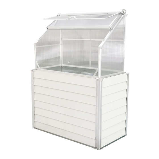
Balcony Mini-Greenhouse
Assembly Instruction
Overall Size/cm: L120 x W62 x H169
Overall Size/inch: L47"x W24.4"x H66.5"
IMPORTANT
You must read these instructions carefully before you start to assembly.
Please ensure that you find all parts in the correct type and
Please carry out the steps according to the instructions.
Do not tighten the steps until completing on
Keep the instruction manuals in a safe place for future reference.
quantity as mentioned in the list.
the assembly of the whole product.
9820510
Advertisement
Table of Contents

Related Manuals for Hanover HANGHGBMN-1WHT


Summary of Contents for Hanover HANGHGBMN-1WHT
- Page 1 Balcony Mini-Greenhouse Assembly Instruction Overall Size/cm: L120 x W62 x H169 Overall Size/inch: L47"x W24.4"x H66.5" 9820510 IMPORTANT You must read these instructions carefully before you start to assembly. Please ensure that you find all parts in the correct type and quantity as mentioned in the list.
-
Page 3: Product Size
SAFETY ADVICE We strongly recommend the use of work gloves during assembly. Do not attempt to assemble the greenhouse in windy or wet conditions, PRODUCT SIZE Do not touch overhead power cables with the aluminum profiles. Always wear shoes and safety goggles when working with extruded aluminum. -
Page 4: Parts List
PARTS LIST Qty. Qty. NO. Qty. NO. Qty. 43.3" 1102mm ST5x30 1102mm 522mm 43.3" ST5x20 20.5" ST5x10 M4x9 350mm 13.8" M6x9 615mm 726mm 28.6" 24.2" ST4x8 1102mm 45.7" M6x12 1161mm 43.3" 522mm M6x10 20.5" 581mm Qty. 22.8" 726mm 28.6" 45.7" 1158mm 0.86"... - Page 5 B10 x2 D2 x4 F3x8 B5 x4 B11 x2 Anchor Installation Ⅰ Ⅱ Attach the anchor B5 to the corner of base B10. Ⅲ Ⅳ Base and Frame Assembly Make sure all holes are all in alignment and then fix B5 anchors onto B10 and D2 by F3 screws. Repeat the step to complete anchor installation for other 3 corners.
- Page 6 B7 x1 B12 x2 F5 x8 F7 x12 Ⅰ Panels of platform B12 Installation Step I: Align holes for D2 and B12. Attach D2 & B12 with 12 pieces F7 screws. Ⅱ Step II: Attach P6 onto B7&B12 with 8 pieces F5 screws. Workbench Assembly Bottom of workbench P6 Installation...
- Page 7 F5 x4 F7 x4 Step 1: Ⅰ Fix the bottom panel P6 to the last piece B7 wall panel with 4 pieces F5 screws. F7 F7 Ⅱ Workbench Assembly Step 2: Install the last piece of wall panel B7 and the two frames D2 with 4 pcs F7 screws.
- Page 8 P8 x2 Water Pipe G3 Installation Back wall panels Installation G3 water pipe kit is composed by 2 parts,including connecting head and pipe. Ⅱ Ⅰ Step 2: Step 1: Insert wall panels P8 into parts D2, Rotate and tighten the water pipe G3. 2 pcs P8 panels for each wall.
- Page 9 P9 x4 Step 2: Step 1: Insert the second piece Insert the first piece wall panel P9 of same side wall panel P9. wall. Ⅱ Ⅰ Ⅲ Ⅳ Ⅴ Side wall panels Installation Step 3: Step 4: Ensure the bottom edge of Insert the second piece the first P9 panel inserted into Ensure the bottom edge of...
-
Page 10: Door Assembly
D1 x2 P7 x2 F6 x10 Step 1: Ⅲ 1.Put the 2 pieces panels P7 together; DOOR 2.Make sure the two panels are against each other; 3.Assemble them together in the middle with 2 pieces F6 screws. Ⅰ back back Door Assembly Edge frame D1 installation. - Page 11 B3 x2 F5 x2 Door sealer S10 Installation Cut the S10 adhesive stripe in 4 pieces,33" long. Stick the 4 pieces on the inside surfaces of the 2 pieces front D2 according to figure I. DOOR Planform of D2 Door Stopper B3 Installation DOOR DOOR There are 2 holes on parts B3.
- Page 12 Installation for base frame of greenhouse. Silicon F5 x10 1 x2 2 x2 Ⅰ Seal the gaps between every two panels. Silicon F5 x10 Silicon Step I: Place10 pieces F5 screws into the pre-drilled holes on the upper Ⅱ surfaces of B7 and B12, then mount the nuts but not fully locked.
- Page 13 F4 x9 3 x2 13 x2 Step I: Place 9 pieces F4 screws into the pre-drilled holtes on 1# profiles but don't fully tighten them. Installation for the frame of greenhouse Ⅰ F4 x9 Ⅱ Step II: Inserting the tail of F4 screws into the frame profiles 3# of mini greenhouse.
- Page 14 9 x2 F8 x2 F4 x13 5 x1 14 x2 7 x2 Ⅰ Ⅲ Ⅱ Step I,II,III,IV Pre-place 13 pieces F4 screws into 7#,9# and 5# parts. Ⅴ Ⅳ Step V Reinforcing rib 9# installation Fix the other end of part 9# on to part 1# with F8 screw.
- Page 15 P3 x2 F4 x7 B1 x2 12 x2 PC Panels for back wall Ⅱ Step II Ⅰ Roof frames installation Step I Pre-place 1 piece F4 screw into each 13# and 6# part. Ⅲ Amplifying detailed figure. Ensure the panels P3 inserted into the groove of part 13.
- Page 16 F6 x3 B6 x2 F4 x9 Ⅲ Ⅰ Ⅱ F4 x1 F4 x1 Step III: Pre-embedding 2 pieces F4 x2 F4 screws in the holes at each end of roof beam 8#. Step I,II: Pre-place 2 pieces F4 screws in each of profile 12. Pre-pance 1 pieces F4 screws in each of profile 13.
-
Page 17: Roof Panel Installation
F4 x2 F3x2 Step I: Roof Panel Installation Pre-place 2xF4 screws Ⅰ Step II: into the profile 10#. Ⅱ Inserting P5 PC panel into frame profiles 12 and cover the end edge with connecting profile 10. F4 x2 Ⅱ Assemble profile 10 on Part B1 and lock them. -
Page 18: Handle Installation
W5 x2 F3x8 F8 x2 W1 x3 W4 x2 S6 x2 Bottom Window Middle Window Window Ⅳ Ⅲ Ⅳ Handle Installation Step IV: Ⅲ Ⅰ 2 pieces F8 screws for one handle. Step III: 1.Note the direction of W4; 2.Note the parts P4 & W1 are involved in the groove Direction of W4. - Page 19 F3x2 11 x2 S3 x2 Ⅰ Installation for rail 11# Insert rail profile 11# into the grooves of profile 10#. Ⅱ Roof corner plastic caps S3 installation. -19-...
- Page 20 F2 x2 F1 x8 S5 x2 Installation for plastic end caps. Ⅰ Install S7L with 2 pieces F1 screws. Install S7R in same way. Ⅱ Install S9L with 2 pieces F1 screws. Install S9R in same way. Install S5 onto S9 with 1 piece F2 screws. -20-...
- Page 21 S1 x2 F3x6 Plastic corner caps S1,S1L and S1R installation Ⅰ Ⅱ Lock all F4,F5,F6,F8 Screws. Congratulation! You did it! -21-...
- Page 22 Display how to open and close the window and door -22-...
Need help?
Do you have a question about the HANGHGBMN-1WHT and is the answer not in the manual?
Questions and answers