Advertisement
Quick Links
Advertisement

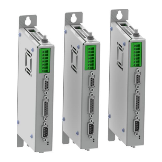
Summary of Contents for NTI AG LinMot B1100-VF
- Page 1 Analog Current Command Interface Quick Start Guide B1100-VF B1100-VF (-HC/-XC)
-
Page 2: Table Of Contents
The information in this documentation reflects the stage of development at the time of press and is therefore without obligation. NTI AG reserves itself the right to make changes at any time and without notice to reflect further technical advance or product improvement. -
Page 3: System Overview
For more detailed information about the functionality of the software please refer to the manuals above: Installation_Guide_B1100.pdf: data sheet, wiring and connections Usermanual_MotionCtrlSW.pdf: motion controller software description (state machine, motion interface) NTI AG, LinMot Quick Start Guide E1100-VF 13/04/2015 Page 3/16... -
Page 4: Connector Overview
Quick Start Guide B1100-VF Connector Overview Typical servo system B1100-XX-YY: Drive, motor and power supply. Page 4 of 16 Quick Start Guide B1100-VF 13.04.2015 NTI AG/ LinMot/... -
Page 5: Getting Started Current Command Mode
Connect your configuration PC using a 1:1 serial RS232 cable (female/female) with the drive’s Switch on the 24V logic supply. Start the LinMot-Talk configuration software. Login the drive. NTI AG, LinMot Quick Start Guide E1100-VF 13/04/2015 Page 5/16... - Page 6 Quick Start Guide B1100-VF Import the B1100_CurrCmd_QuickStart_Cfg.lmc configuration file: The following description is a short tour through the imported configuration. Page 6 of 16 Quick Start Guide B1100-VF 13.04.2015 NTI AG/ LinMot/...
-
Page 7: Io Configuration
Quick Start Guide B1100-VF IO Configuration In the quick start configuration the digital inputs and outputs are configured as shown: NTI AG, LinMot Quick Start Guide E1100-VF 13/04/2015 Page 7/16... - Page 8 Quick Start Guide B1100-VF The differential analog voltage input is configured as a current command input: Page 8 of 16 Quick Start Guide B1100-VF 13.04.2015 NTI AG/ LinMot/...
- Page 9 Quick Start Guide B1100-VF The scaling is done with the 10V current value and may be adapted regarding the motor’s and drive’s maximal current: NTI AG, LinMot Quick Start Guide E1100-VF 13/04/2015 Page 9/16...
- Page 10 In the next step the state machine is set to the special mode “Current Command Mode”: Now the motor can be configured with the motor wizard. The motor wizard guides you through the configuration: Page 10 of 16 Quick Start Guide B1100-VF 13.04.2015 NTI AG/ LinMot/...
- Page 11 Quick Start Guide B1100-VF NTI AG, LinMot Quick Start Guide E1100-VF 13/04/2015 Page 11/16...
- Page 12 Quick Start Guide B1100-VF Page 12 of 16 Quick Start Guide B1100-VF 13.04.2015 NTI AG/ LinMot/...
- Page 13 2um sensor simulation resolution. When the motor wizard is finished all the needed parameters are set accordingly. The system is now ready for operation. Switch on the motor supply. NTI AG, LinMot Quick Start Guide E1100-VF 13/04/2015 Page 13/16...
- Page 14 X14 5 is set. This indicates that the homing sequence has been completed. Set the input on X14.2 low to complete the homing. By setting the input on X14.3 the current command interface will be activated! Page 14 of 16 Quick Start Guide B1100-VF 13.04.2015 NTI AG/ LinMot/...
- Page 15 Otherwise the motor will accelerate in any direction and crash to a limit! If an error occurs, the output on X14.6 will go high. It can be acknowledged by a rising edge on the input X14.15. NTI AG, LinMot Quick Start Guide E1100-VF 13/04/2015 Page 15/16...
-
Page 16: Contact Addresses
Quick Start Guide B1100-VF Contact Addresses ----------------------------------------------------------------------------------------------------------------------------- SWITZERLAND NTI AG Haerdlistr. 15 CH-8957 Spreitenbach Sales and Administration: +41-(0)56-419 91 91 office@linmot.com Tech. Support: +41-(0)56-544 71 00 support@linmot.com skype:support.linmot Tech. Support (Skype) : Fax: +41-(0)56-419 91 92 http://www.linmot.com/ Web: ----------------------------------------------------------------------------------------------------------------------------- LinMot, Inc.


Need help?
Do you have a question about the LinMot B1100-VF and is the answer not in the manual?
Questions and answers