Table of Contents

Related Manuals for NTI AG LinMot C1400 Series


Summary of Contents for NTI AG LinMot C1400 Series
- Page 1 C1400 Servo Drives Installation Guide Eine Deutsche Version kann unter http://www.linmot.com bezogen werden! Please visit http://www.linmot.com to check for the latest version of this document! 0185-1107-E_6V4_IG_C1400 / May 2015...
- Page 2 The information in this documentation reflects the stage of development at the time of press and is therefore without obligation. NTI AG reserves itself the right to make changes at any time and without notice to reflect further technical advance or product improvement.
-
Page 3: Table Of Contents
5.12 S1 - S2 - S5......................14 6 Error Codes........................15 7 Physical Dimensions.....................16 8 Power Supply Requirements..................17 9 Regeneration of Power / Regeneration Resistor............17 10 Ordering Information....................18 11 International Certifications..................18 12 Declaration of Conformity CE-Marking..............20 13 Contact Addresses......................21 NTI AG / LinMot ® www.LinMot.com Page 3/20... -
Page 4: Important Safety Instructions
• It is up to the user to check whether they can be transferred to the particular applications. NTI AG / LinMot does not accept any liability for the suitability of the procedures and circuit proposals described. LinMot servo drives and the accessory components can include live and moving parts (depending on •... - Page 5 PE connection is required. The heat sink of the drive has an operating temperature of > 80 °C: Contact with the • heat sink results in burns. NTI AG / LinMot ® www.LinMot.com Page 5/20...
-
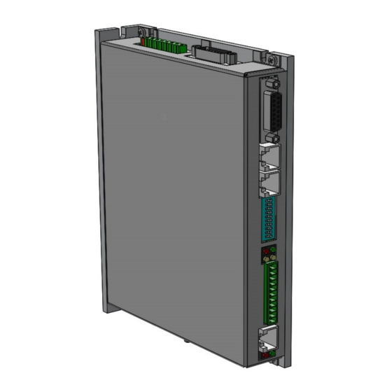
Page 6: System Overview
C1400 Installation Guide preliminary 2 System Overview Page 6/20 www.LinMot.com NTI AG / LinMot ®... -
Page 7: Functionality And Interfaces
● ● ● ● ● ● ● Configuration Interface RS232 ● ● ● ● ● ● ● ● ● ● 1Additional cooling and/or heat sink may be required to achieve rated performance NTI AG / LinMot ® www.LinMot.com Page 7/20... -
Page 8: Power Supply And Grounding
Each system component should be tied directly to the ground bus (star pattern), rather than daisy chaining from component to component. (LinMot motors are properly grounded through their power cables when connected to LinMot drives.) Page 8/20 www.LinMot.com NTI AG / LinMot ®... -
Page 9: Description Of The Connectors / Interfaces
- Conductor cross-section: 2.5mm (AWG 12) - Stripping length 7mm LinMot Article Number: 0150-3607 (DC01-C1400/X30) Operating of the drive is only allowed with the above article! No other type of connector shall be used! NTI AG / LinMot ® www.LinMot.com Page 9/20... - Page 10 GND Sense +5V Sense Cos- Cos+ Sin- Sin+ case shield DSUB-15 (m) Motor Link C is a high speed serial communication protocol to the motor encoder. Page 10/20 www.LinMot.com NTI AG / LinMot ®...
-
Page 11: X13
Max Output Frequency: 4 M counts/s with quadrature decoding, 250ns edge separation Differential Hall Switch Inputs (RS422): Input Frequency: <1kHz Enc. Alarm In: 5V / 1mA Sensor Supply: 5VDC max. 100mA / 9VDC 100mA (SW selectable) NTI AG / LinMot ® www.LinMot.com Page 11/20... -
Page 12: X17 - X18
S5.9. X7 is internally connected to X8 (Pin4, 5, 7 and 8) 5.9 X19 System Do not connect Do not connect RS232 Rx RS232 Tx Do not connect Do not connect RJ-45 Use isolated USB-RS232 converter (Art.-No. 0150-2473) for configuration over RS232. Page 12/20 www.LinMot.com NTI AG / LinMot ®... -
Page 13: Leds
Bus ID Low (0 … F). Bit 1 is the LSB, bit 4 the MSB. The use of these switches depends on the type of fieldbus which is used. Please see the corresponding manual for further information. NTI AG / LinMot ® www.LinMot.com... -
Page 14: Error Codes
The meaning of the error codes can be found in the Usermanual_MotionCtrl_Software_SG5 and the user manual of the installed interface software. These documents are provided together with LinMot-Talk configuration software and can be downloaded from www.linmot.com. Page 14/20 www.LinMot.com NTI AG / LinMot ®... -
Page 15: Physical Dimensions
Additional cooling and/or heat sink may be required to achieve rated performance Mounting place In the control cabinet Mounting position vertical Distance between drives mm (in) ≥ 15 (0.6) left and right ≥ 200 (8) top / bottom NTI AG / LinMot ® www.LinMot.com Page 15/20... -
Page 16: Power Supply Requirements
The max. threshold value must not exceed 780 VDC. Item Description Art. No. Regeneration Resistor RR01-68/100 (68 Ohm, 100 W, X1 connector is included) 0150-3373 Page 16/20 www.LinMot.com NTI AG / LinMot ®... -
Page 17: Ordering Information
ATTENTION: The connectors have to be ordered separately and are not included with the drive! Use isolated USB RS232 converter for configuration! 11 International Certifications Certifications Europe See chapter “12 EC Declaration of Conformity CE-Marking“ UL508C pending NTI AG / LinMot ® www.LinMot.com Page 17/20... - Page 18 C1400 Installation Guide preliminary Page 18/20 www.LinMot.com NTI AG / LinMot ®...
-
Page 19: Declaration Of Conformity Ce-Marking
EC directive. The product must be mounted and used in strict accordance with the installation instructions contained within the installation guide, a copy of which may be obtained from NTI AG. Company: NTI AG Spreitenbach, March 13, 2014... -
Page 20: Contact Addresses
Elkhorn, WI 53121 Sales and Administration: 877-546-3270 262-743-2555 Tech. Support: 877-804-0718 262-743-1284 Fax: 800-463-8708 262-723-6688 E-Mail: usasales@linmot.com Web: http://www.linmotusa.com/ Please visit http://www.linmot.com/ to find the distributor closest to you. Smart solutions are… Page 20/20 www.LinMot.com NTI AG / LinMot ®...
Need help?
Do you have a question about the LinMot C1400 Series and is the answer not in the manual?
Questions and answers