Table of Contents
Advertisement
Quick Links
PRELIMINARY
E14x0 Servo Controller
Installation Guide
Eine Deutsche Version kann unter http://www.linmot.com bezogen werden!
Please visit http://www.linmot.com to check for the latest version of this document!
This document applies to the following controllers:
E1400-GP-QN
E1430-DP-QN
E1450-PL-QN
E1450-EC-QN
E1450-PN-QN
E1450-IP-QN
E1450-SC-QN
Advertisement
Table of Contents

Related Manuals for NTI AG LinMot E14 0 Series


Summary of Contents for NTI AG LinMot E14 0 Series
- Page 1 PRELIMINARY E14x0 Servo Controller Installation Guide Eine Deutsche Version kann unter http://www.linmot.com bezogen werden! Please visit http://www.linmot.com to check for the latest version of this document! This document applies to the following controllers: E1400-GP-QN E1430-DP-QN E1450-PL-QN E1450-EC-QN E1450-PN-QN E1450-IP-QN E1450-SC-QN...
- Page 2 The information in this documentation reflects the stage of development at the time of press and is therefore without obligation. NTI AG reserves itself the right to make changes at any time and without notice to reflect further technical advance or product improvement.
-
Page 3: Table Of Contents
7 Error Codes........................16 8 Safety Wiring........................17 9 Physical Dimensions.....................18 10 Power Supply Requirements..................19 11 Regeneration of Power / Regeneration Resistor............19 12 Ordering Information....................20 13 International Certifications..................20 14 Declaration of Conformity CE-Marking..............21 15 Contact Addresses......................24 NTI AG / LinMot ® www.LinMot.com Page 3/24... -
Page 4: Important Safety Instructions
• It is up to the user to check whether they can be transferred to the particular applications. NTI AG / LinMot does not accept any liability for the suitability of the procedures and circuit proposals described. LinMot servo controllers and the accessory components can include live and moving parts •... - Page 5 PE connection is required. The heat sink of the controller has an operating temperature of > 80 °C: Contact with • the heat sink results in burns. NTI AG / LinMot ® www.LinMot.com Page 5/24...
-
Page 6: System Overview
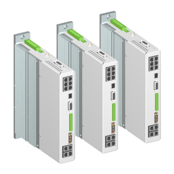
E1400 Installation Guide preliminary 2 System Overview Typical Servo System E14x0-XX: Servo Controller, Motor and Power Supply. ® Page 6/24 www.LinMot.com NTI AG / LinMot... -
Page 7: Functionality And Interfaces
169.254.255.254 (Subnet Mask 255.255.0.0). Please note that this process can take up to a minute until a valid address is assigned to the controller. 1 Firmware support planned 2 Firmware support planned NTI AG / LinMot ® www.LinMot.com Page 7/24... -
Page 8: Power Supply And Grounding
Each system component should be tied directly to the ground bus (star pattern), rather than daisy chaining from component to component. (LinMot motors are properly grounded through their power cables when connected to LinMot controllers.) ® Page 8/24 www.LinMot.com NTI AG / LinMot... -
Page 9: Description Of The Connectors / Interfaces
- Use a cross-head screw driver (PH1) - Use 60/75°C copper conductors only - Conductor cross-section: 0.25 – 4 mm (depends on Motor current) / AWG 24 -12 - Stripping length 10mm NTI AG / LinMot ® www.LinMot.com Page 9/24... - Page 10 - Conductor cross-section max. 1.5mm - Internal Fuse (F2): 3AT (slow blow, Schurter OMT125, 3404.0118.xx, UL File Number: E41599) CAUTION: For continued protection against risk of fire, replace only with same type and rating of fuse. ® Page 10/24 www.LinMot.com NTI AG / LinMot...
-
Page 11: X7 - X8
X7 is internally connected to X8 (1:1 connection) 6.7 X9 PROFIBUS DP (only available on E1430-DP-QN) Not connected (isolated) Not connected Not connected RxD/TxD-P RxD/TxD-N CNTR-P Not connected (isolated) case Shield DSUB-9 (f) Max. Baud rate: 12Mbaud NTI AG / LinMot ® www.LinMot.com Page 11/24... -
Page 12: X10 - X11
Max Output Frequency: 25 M counts/s with quadrature decoding, 40ns edge separation Differential Hall Switch Inputs (RS422): Input Frequency: <1kHz Enc. Alarm In: 5V / 1mA Sensor Supply: 5VDC max. 100mA / 9VDC 100mA (SW selectable) ® Page 12/24 www.LinMot.com NTI AG / LinMot... -
Page 13: X15 - X16
RJ-45 6.12 System Do not connect Do not connect RS232 Rx RS232 Tx Do not connect Do not connect case Shield RJ-45 Use adapter cable AC01-RJ45/Df-2.5-RS1 (Art.-No. 0150-2143) for configuration over RS232. NTI AG / LinMot ® www.LinMot.com Page 13/24... -
Page 14: X20
Switch 1: AnIn2 pull down (4k7 Pull down on X4.4). Set to ON, if X4.4 is used as digital output. Factory setting: all switches “on” except S5.5 (Bootstrap) and S5.6 (Override to DHCP) ® Page 14/24 www.LinMot.com NTI AG / LinMot... -
Page 15: Leds
Bus ID Low (0 … F). Bit 1 is the LSB, bit 4 the MSB. The use of these switches depends on the type of fieldbus which is used. Please see the corresponding manual for further information. NTI AG / LinMot ® www.LinMot.com... -
Page 16: Error Codes
The meaning of the error codes can be found in the Usermanual_MotionCtrl_Software_SG5 and the user manual of the installed interface software. These documents are provided together with LinMot-Talk configuration software and can be downloaded from www.linmot.com. ® Page 16/24 www.LinMot.com NTI AG / LinMot... -
Page 17: Safety Wiring
Safety Relay Ksr Nominal voltage 24 VDC Min. pick-up voltage at 20°C ≤ 16.8V Drop-out voltage at 20°C ≥ 2.4 V Coil resistance at 20°C 2'100 Ω ± 10% Type EN 50205, type A NTI AG / LinMot ® www.LinMot.com Page 17/24... -
Page 18: Physical Dimensions
≥ 40 (1.6) left (heat sink side) option EV01-E1400) ≥ 5 (0.2) right ≥ 200 (8) top / bottom Distance between Controllers (cold plate mm (in) ≥ 0 (0) left/right cooling) ≥ 200 (8) top / bottom ® Page 18/24 www.LinMot.com NTI AG / LinMot... -
Page 19: Power Supply Requirements
The max. threshold value must not exceed 780 VDC. Item Description Art. No. Regeneration Resistor RR01-68/100 (68 Ohm, 100 W) 0150-3373 NTI AG / LinMot ® www.LinMot.com Page 19/24... -
Page 20: Ordering Information
2.5m Regeneration resistor (68R, 100W, 1000V) 0150-3373 RR01-68/100 EV01-E1400 Fan Option for E1400 0150-5055 3-phase line filter (tbd) 13 International Certifications Certifications Europe See chapter “14 Declaration of Conformity CE-Marking“ UL508C pending ® Page 20/24 www.LinMot.com NTI AG / LinMot... -
Page 21: Declaration Of Conformity Ce-Marking
EN 5022 Radio disturbance (IT equipment) EN 5011 Radio disturbance (ISM) CISPR 22: 2005 Radio disturbance (IT equimpment) Company: NTI Ltd. Spreitenbach, June 07, 2011 ----------------------------------------------------------- R. Rohner / CEO NTI AG NTI AG / LinMot ® www.LinMot.com Page 21/24... - Page 22 E1400 Installation Guide preliminary ® Page 22/24 www.LinMot.com NTI AG / LinMot...
- Page 23 Preliminary E1400 Installation Guide NTI AG / LinMot ® www.LinMot.com Page 23/24...
-
Page 24: Contact Addresses
Elkhorn, WI 53121 Sales and Administration: 877-546-3270 262-743-2555 Tech. Support: 877-804-0718 262-743-1284 Fax: 800-463-8708 262-723-6688 E-Mail: us-sales@linmot.com Web: http://www.linmot-usa.com/ Please visit http://www.linmot.com/ to find the distributor closest to you. Smart solutions are… ® Page 24/24 www.LinMot.com NTI AG / LinMot...
Need help?
Do you have a question about the LinMot E14 0 Series and is the answer not in the manual?
Questions and answers