Table of Contents
Advertisement
Quick Links
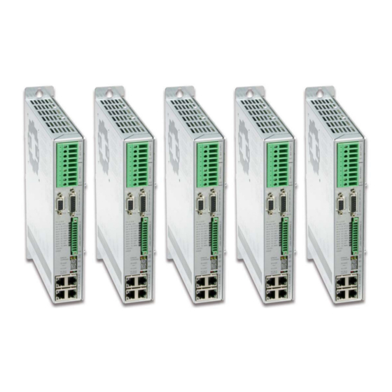
E1200 Servo Controller
Installation Guide
Eine Deutsche Version kann unter http://www.linmot.com bezogen werden!
Please visit http://www.linmot.com to check for the latest version of this document!
This document applies to the following controllers:
E1200-GP-UC
E1230-DP-UC
E1250-PL-UC
E1250-EC-UC
E1250-PN-UC
E1250-IP-UC
E1250-SC-UC
Advertisement
Table of Contents

Related Manuals for NTI AG LinMot E1200 Series


Summary of Contents for NTI AG LinMot E1200 Series
- Page 1 E1200 Servo Controller Installation Guide Eine Deutsche Version kann unter http://www.linmot.com bezogen werden! Please visit http://www.linmot.com to check for the latest version of this document! This document applies to the following controllers: E1200-GP-UC E1230-DP-UC E1250-PL-UC E1250-EC-UC E1250-PN-UC E1250-IP-UC E1250-SC-UC...
- Page 2 The information in this documentation reflects the stage of development at the time of press and is therefore without obligation. NTI AG reserves itself the right to make changes at any time and without notice to reflect further technical advance or product improvement.
-
Page 3: Table Of Contents
8 Physical Dimensions.....................16 9 Power Supply Requirements..................17 10 Regeneration of Power / Regeneration Resistor............18 11 Ordering Information....................18 12 International Certifications..................18 13 Classification of the safety functionality..............19 14 Declaration of Conformity CE-Marking..............19 15 Contact Addresses......................20 ® NTI AG / LinMot www.LinMot.com Page 3/20... -
Page 4: Important Safety Notes For E1200 Series Controllers
LinMot controllers LEDs have turned off. (Capacitors may not fully discharge for several minutes after power has been turned off). Failure to observe these precautions may result in severe damage to electronic components in LinMot motors and/or controllers. ® NTI AG / LinMot www.LinMot.com Page 4/20... -
Page 5: System Overview
LinMot Installation Guide 2 System Overview Typical Servo System E12x0-XX: Servo Controller, Linear Motor and Power Supply. ® NTI AG / LinMot www.LinMot.com Page 5/20... -
Page 6: Functionality And Interfaces
169.254.0.1 through 169.254.255.254 (Subnet Mask 255.255.0.0). Please note that this process can take up to a minute until a valid address is assigned to the controller. * LinMot Motor Communication ® NTI AG / LinMot www.LinMot.com Page 6/20... -
Page 7: Power Supply And Grounding
* Inside of the E1200 controller the PWR motor GND and PWR signal GND is connected together and to the GND of the controller housing. It is recommended that the PWR motor GND is NOT grounded at another place than inside of the controller to reduce circular currents. ® NTI AG / LinMot www.LinMot.com Page 7/20... -
Page 8: Description Of The Connectors / Interfaces
- Tightening torque: 0.5 - 0.6 Nm - Screw thread: M2.5 - Use 60/75°C copper conductors only - Conductor cross-section: 0.5 – 2.5mm (depends on Motor current) / AWG 21 -14 - Stripping length 13-15mm ® NTI AG / LinMot www.LinMot.com Page 8/20... - Page 9 DSUB-9 (f) Note : Use +5VDC (X3.3) and AGND (X3.8) only for motor internal hall sensor supply (max. 100mA). Caution : Do NOT connect AGND (X3.8) to ground or earth! Motor Wiring ® NTI AG / LinMot www.LinMot.com Page 9/20...
-
Page 10: X7 - X8
Use twisted pair (1-2, 3-6, 4-5, 7-8) cable for wiring. The built in CAN and RS485 terminations can be activated by S5.2 and S5.3. X7 is internally connected to X8 (1:1 connection) ® NTI AG / LinMot www.LinMot.com Page 10/20... -
Page 11: X10 - X11
Master Encoder Outputs: Amplified RS422 differential signals from Master Encoder IN (X10) The CAN bus can be terminated with S5.4. All devices, which are connected to X10/X11 must be referenced to the same ground. ® NTI AG / LinMot www.LinMot.com Page 11/20... -
Page 12: X13
Config Ethernet 10/100 Mbit/s Internal 2-Port 10BASE-T and 100BASE-TX Ethernet Switch with Auto MDIX. LEDs on the lower side of the device indicate “Link/Activity” per port, the upper ones are not used. RJ-45 ® NTI AG / LinMot www.LinMot.com Page 12/20... -
Page 13: X17 - X18
Use Adapter cable AC01-RJ45/Df-2.5-RS1 (Art.-No. 0150-2143) for Configuration over RS232. 6.12 Analog In (+-10V Differential Analog Input) (Do not connect) (Do not connect) Analog In - Analog In + (Do not connect) (Do not connect) case Shield RJ-45 ® NTI AG / LinMot www.LinMot.com Page 13/20... -
Page 14: Leds
Bus ID Low (0 … F). Bit 1 is LSB, bit 4 MSB. The use of these switches depends on the type of fieldbus which is used. Please see the corresponding manual for further information. ® NTI AG / LinMot www.LinMot.com Page 14/20... -
Page 15: Error Codes
18VDC. meaning error codes found Usermanual_MotionCtrlSW_SG5 and the user manual of the installed interface software. These documents are provided together with LinMot-Talk configuration software and can be downloaded from www.linmot.com. ® NTI AG / LinMot www.LinMot.com Page 15/20... -
Page 16: Physical Dimensions
0…40 at rated data 40...50 with power derating Relative humidity 95% (non-condensing) Max. Case Temperature °C Max. Power Dissipation Distance between mm (in) 20 (0.8) left/right Controllers 50 (2) top / bottom ® NTI AG / LinMot www.LinMot.com Page 16/20... -
Page 17: Power Supply Requirements
200mA (no load on the outputs) typ. 1.1A (all 10 outputs “on” with 100mA load and /Break with no load) max. 2.1A (all 10 outputs “on” with 100mA load and /Break with 1A load) ® NTI AG / LinMot www.LinMot.com Page 17/20... -
Page 18: Regeneration Of Power / Regeneration Resistor
72VDC/32A 0150-1761 E1230-DP-UC PROFIBUS-DP Servo Controller 72VDC/32A 0150-1766 E1200-GP-UC GENERAL PURPOSE Servo Controller 72VDC/32A 0150-1771 RS232 AC01-RJ45/Df-2.5-RS1 0150-2143 configuration cable 12 International Certifications Certifications Europe See chapter “14 Declaration of Conformity CE-Marking“ ® NTI AG / LinMot www.LinMot.com Page 18/20... -
Page 19: Classification Of The Safety Functionality
Power frequency magnetic field immunity EN 61000-6-4 Emission for industrial environment EN 55022 Class B Radiated Emission Company: NTI Ltd. / Spreitenbach / October 13, 2010 -------------------------------------------- R. Rohner / CEO NTI AG ® NTI AG / LinMot www.LinMot.com Page 19/20... -
Page 20: Contact Addresses
Elkhorn, WI 53121 Sales and Administration: 877-546-3270 262-743-2555 Tech. Support: 877-804-0718 262-743-1284 Fax: 800-463-8708 262-723-6688 E-Mail: us-sales@linmot.com Web: http://www.linmot-usa.com/ Please visit http://www.linmot.com/ to find the distributor closest to you. Smart solutions are… ® NTI AG / LinMot www.LinMot.com Page 20/20...
Need help?
Do you have a question about the LinMot E1200 Series and is the answer not in the manual?
Questions and answers