Sign In
Upload
Download
Table of Contents
Contents
Add to my manuals
Delete from my manuals
Share
URL of this page:
HTML Link:
Bookmark this page
Add
Manual will be automatically added to "My Manuals"
Print this page
×
Bookmark added
×
Added to my manuals
Manuals
Brands
Sigicom Manuals
Measuring Instruments
INFRA V10
Manual
Sigicom INFRA V10 Manual
Geophone
Hide thumbs
1
2
3
Table Of Contents
4
5
6
7
8
9
10
11
12
13
14
15
16
17
18
19
20
21
22
23
24
25
26
27
28
29
30
31
32
33
34
35
36
37
38
39
40
41
42
43
44
45
46
47
48
page
of
48
Go
/
48
Contents
Table of Contents
Bookmarks
Table of Contents
Table of Contents
Introduction
About this Manual
Features
Unpacking and Parts Identification
General Description
Design Features
Measurement Standards
Measurement Data
Display Device
Configuration and Operation
Mounting
Parameters
Quick Start V10 and V11
Quick Start V12
The LED
Consider this
Post-Processing of Data
Maintenance and Calibration
Accessories
Specific Accessories
Other Accessories
Contact and Support
Appendix A Specifications
Reference Conditions (Factory Calibration)
Accuracy
Overload Handling
Power Consumption
Mechanical Data
Approvals
Appendix B Glossary
Appendix C Standards
Appendix D Example of Using a Weighting Standard
Appendix E Removed Standards
Advertisement
Quick Links
Download this manual
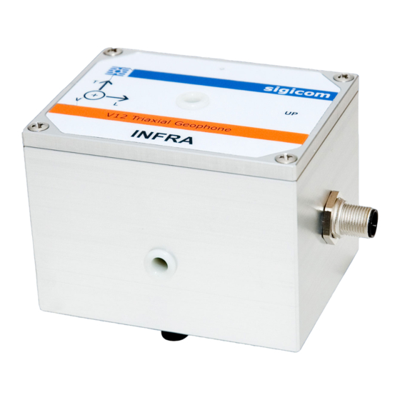
INFRA V10, V11 and
V12
Geophone
Art no.
080-03110-0,
080-03111-0 and
080-03112-0
Manual
ver. I
Copyright ©Sigicom AB
Valid for firmware version 2.2
Art.no ML089-0311x-0En
Manual
Table of
Contents
Previous
Page
Next
Page
1
2
3
4
5
Advertisement
Table of Contents
Need help?
Do you have a question about the INFRA V10 and is the answer not in the manual?
Ask a question
Questions and answers
Related Manuals for Sigicom INFRA V10
Measuring Instruments Sigicom INFRA V12 Manual
Geophone (48 pages)
Measuring Instruments Sigicom INFRA C20 Manual
Wireless vibration monitor (58 pages)
Measuring Instruments Sigicom INFRA C22 Manual
Wireless vibration monitor (77 pages)
Measuring Instruments Sigicom INFRA S50 Manual
Sound level meter (36 pages)
Measuring Instruments Sigicom INFRA S51 Manual
Sound level meter -with infrasound capabilities (35 pages)
Measuring Instruments Sigicom INFRA Point Manual
Vertical/triaxial vibration system (65 pages)
Measuring Instruments Sigicom INFRA C22 Manual
Wireless vibration monitor (77 pages)
Measuring Instruments Sigicom INFRA Master User Manual
(58 pages)
This manual is also suitable for:
Infra v11
Infra v12
Table of Contents
Print
Rename the bookmark
Delete bookmark?
Delete from my manuals?
Login
Sign In
OR
Sign in with Facebook
Sign in with Google
Upload manual
Upload from disk
Upload from URL


Need help?
Do you have a question about the INFRA V10 and is the answer not in the manual?
Questions and answers