
Related Manuals for ETOP ISA-E2

Summary of Contents for ETOP ISA-E2
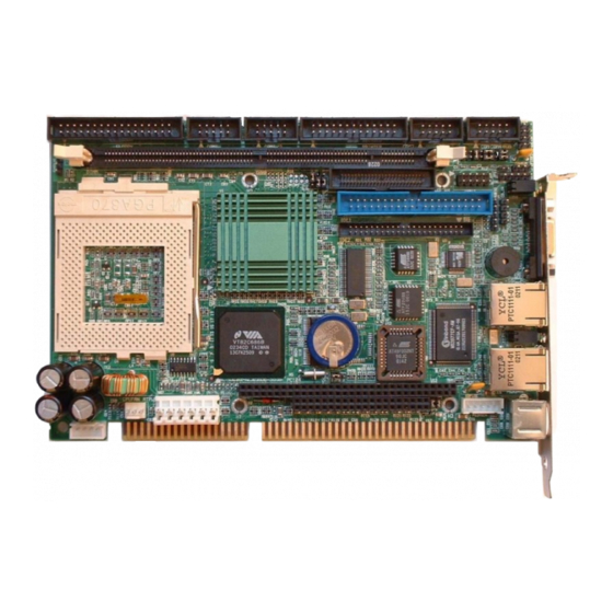
- Page 1 Pentium III Half-Size CPU Card With VGA, Audio & Dual LAN User’s Manual Version 1.4...
- Page 2 IBM, PS/2 are trademarks of International Business Machines Corporation. Intel, PentiumIII and Celeron are registered trademarks of Intel Corporation. Microsoft Windows is a registered trademark of Microsoft Corporation. All other product names or trademarks are properties of their respective owners. ISA-E2 User’s Manual...
-
Page 3: Table Of Contents
Intelligence ................9 Chapter 2 Installation ........11 CPU Installation..............12 Memory Installation .............12 Jumpers on the ISA-E2 ............13 Jumper Locations on the ISA-E2..........14 JP5 ~ JP6: CPU Frequency Selector........15 JP7 LCD PANEL Power Selection.........16 JP8: CMOS RAM Data ............16 JP9 JP10: WatchDog Timer Period Selection ......17 JPCOM4: COM2 RS232/RS422/RS485 Selection....17... - Page 4 Advanced BIOS Features ............48 Virus Warning ................48 CPU Internal Cache/External Cache ........49 CPU L2 Cache ECC Checking..........49 Processor Number Feature .............49 Quick Power On Self Test............49 First/Second/Third/Other Boot Device ........49 Swap Floppy Drive..............49 Boot Up Floppy Seek .............49 ISA-E2 User’s Manual...
- Page 5 Init Display First ..............58 IDE HDD Block Mode ............58 Onboard FDC Controller ............58 Onboard Serial Port 1/Port 2...........59 UART 2 Mode ................59 IR Function Duplex ..............59 TX,RX inverting enable............59 Onboard Parallel Port .............59 Onboard Parallel Port Mode ...........59 ISA-E2 User’s Manual...
- Page 6 Frequency/Voltage Control ..........68 Auto Detect DIMM/PCI CLK ..........68 Spread Spectrum Modulated ..........68 CPU Host Clock (CPU/PCI) ..........68 Load Fail-Safe Defaults............69 Load Optimized Defaults.............69 Supervisor/User Password Setting........70 Exit Selecting ................71 Save & Exit Setup ..............71 Exit Without Saving ...............71 ISA-E2 User’s Manual...
- Page 7 Contents Appendix ............72 A. I/O Port Address Map .............73 B. Interrupt Request Lines (IRQ) ........74 C. POST Beep................75 ISA-E2 User’s Manual...
-
Page 9: Chapter 1 Introduction
Chapter 1 Introduction Introduction This manual is designed to give you information on the ISA-E2 SBC card. The topics covered in this chapter are as follows: ♦ Checklist ♦ Description ♦ Features ♦ Specifications ♦ Intelligence ISA-E2 User’s Manual... -
Page 10: Checklist
User’s manual. PS/2 Keyboard and Mouse 1-to-2 Y-cable Description The ISA-E2 is a Pentium III Industrial single board computer (SBC) card based on VIA 8606 chipset and is fully designed for harsh industrial environment. It features one Socket370, that is compatible with Intel FC-PGA package Pentium III processor. - Page 11 133 MHz. The ISA-E2 comes with VIA integrated hardware monitoring device that monitors system and CPU temperature, voltages of all system power rails, and CPU fan speeds to prevent system crashes by warning the user of adverted conditions.
-
Page 12: Features
Low-Power Processors: Fully support Intel Coppermine, Tualatin and VIA C3 processor. Both Intel Tualatin and VIA C3 CPU adapt 0.13 process and operate at lower voltage. This provide the ISA-E2 system as a low power consumption system. • VIA Twister-T AGPset: Features VIA Twsiter-T AGPset... - Page 13 3D Enhanced AC97 Audio Codec: ALC201A features the high S/N ratio (> 90dB) and 3D enhancement. pin-headers allow user to wire CD_IN, Line-out and Mic signals to Front panel or bridge board. Complete OS drivers and Applications are bundled in Driver CD. ISA-E2 User’s Manual...
-
Page 14: Specifications
Enhanced ACPI BIOS and DMI 2.0 ISA Plug and Play (PnP) extension Power management Anti-Boot Virus • DMI BIOS Support: Desktop Management Interface (DMI) allows users to download system hardware-level information such as CPU type, CPU speed, internal/external frequencies and memory size. ISA-E2 User’s Manual... - Page 15 On-board 4-pin ATX power supply header (requires the passive backplane supports ATX power supply) On-board power button header for Soft power off, i.e. front panel turn off system power. Support Win95 and Win98 shutdown automatically turn off the system power. ISA-E2 User’s Manual...
- Page 16 Power Supply: 5A@ +5v typical; 300mA@ +12v typical 100mA@ -12V typical; 200mA@ +5VSTB (Option) Temperature: 0°C to 60°C operating; -40°C to 70°C storage Humidity: 5% to 95% Dimensions: 7.28"(L) x 5.0"(W) or 185mm (L) x 127mm (W) ISA-E2 User’s Manual...
-
Page 17: Intelligence
ISA half-size card form factor. The Secondary IDE connector is designed with 44-pin 2mm pitch connector. This allow user connector to a 2.5” HDD directly with out any bridge board. DOM users can choose 44-pin DOM for small package and save power cable connector. ISA-E2 User’s Manual... - Page 18 Chapter 1 Introduction This page is intentionally left blank. ISA-E2 User’s Manual...
-
Page 19: Chapter 2 Installation
Installations This chapter provides information on how to use the jumpers and connectors on the ISA-E2 in order to set up a workable system. The topics covered are: CPU Installation..............12 Memory Installation............... 12 Jumpers on the ISA-E2 ............13 Connectors on the ISA-E2 ............. -
Page 20: Cpu Installation
Chapter 3 BIOS Configuration CPU Installation The ISA-E2 Industrial SBC Card provides a 370-pins ZIF socket for Pentium II/III-processors and Celeron with FC-PAG and PPGA (Plastic Pin Grid Array) package. Before installing the processor into the Socket, ensure that the CPU fan is installed first. -
Page 21: Jumpers On The Isa-E2
Chapter3 BIOS Configuration Jumpers on the ISA-E2 The jumpers on the ISA-E2 allow you to configure your SBC card according to the needs of your applications. If you have doubts about the best jumper configuration for your needs, contact your dealer or sales representative. The following table lists the jumpers on ISA-E2 and their respective functions. -
Page 22: Jumper Locations On The Isa-E2
Chapter 3 BIOS Configuration Jumper Locations on the ISA-E2 JCOM4 JP5 JP6 JP10 JP9 P10 ISA-E2 User’s Manual... -
Page 23: Jp5 ~ Jp6: Cpu Frequency Selector
The CPU clock speed showed on the Boot message is not necessarily present the Memory Bus speed. User’s may program the BIOS setup to run Memory bus in different speed. Overclocking your processor and SDRAM module is not recommended. There is no guarantee for any over-speed operation. ISA-E2 User’s Manual... -
Page 24: Jp7 Lcd Panel Power Selection
(4) Put Jumper cap back to pin1& 2. (5) Turn on your computer, (6) Hold Down <Delete> during bootup and enter BIOS setup to enter your preferences. Setting Function Pin 1-2 Short/Closed Normal Operation (default) Pin 2-3 Short/Closed Clear CMOS Content ISA-E2 User’s Manual... -
Page 25: Jp9 Jp10: Watchdog Timer Period Selection
The COM4 port can be configured to operate with external devices on different interface mode. They are RS-232, RS-422 and RS485. JPCOM4. The following table describes how to configure the COM4 interface. JPCOM4 I/F TYPE RS-232 RS-422 RS-485 ISA-E2 User’s Manual... -
Page 26: Connectors On The Isa-E2
Chapter 3 BIOS Configuration Connectors on the ISA-E2 The connectors on the ISA-E2 allows you to connect external devices such as keyboard, floppy disk drives, hard disk drives, printers, etc. The following table lists the connectors on ISA-E2 and their respective page number. -
Page 27: Connector Locations On The Isa-E2
Chapter3 BIOS Configuration Connector Locations on the ISA-E2 IDE1 COM4 FLOPPY COM1 COM2 PRINTER IDE2 COM3 FRONT CANBUS ISOCAN CD_IN Audio Port A Port B ATX PWR AT P8 PC104 PS2KB PS2KB+MS ISA-E2 User’s Manual... -
Page 28: Front Panel Connector
LED will flash when the HDD is being accessed. IDE LED Signal Name Pin # IDE_ACT Ground Power-ON LED Connector The Power LED provide and interface to wire the system power on signal to front panel IDE LED Signal Name Pin # Ground ISA-E2 User’s Manual... -
Page 29: Cpu Fan Power Connector
This is a 3-pin header for the CPU fan. The fan must be a 12V fan. Pin # Signal Name Rotation +12V Ground USB Connectors The following table shows the pin outs of the USB connectors. USB1 USB0 Signal Name Pin# Pin # USB- USB+ Ground N.C. ISA-E2 User’s Manual... -
Page 30: Eide Connectors
Host data 0 Host data 15 Ground DRQ0 Ground Host IOW Ground Host IOR Ground IOCHRDY Host ALE DACK0 Ground IRQ14 No connect Address 1 No connect Address 0 Address 2 Chip select 0 Chip select 1 Activity Ground ISA-E2 User’s Manual... - Page 31 Host data 15 Ground DRQ1 Ground Host IOW Ground Host IOR Ground IOCHRDY Host ALE DACK1 Ground IRQ15 No connect Address 1 No connect Address 0 Address 2 Chip select 0 Chip select 1 Activity Ground Ground No connect ISA-E2 User’s Manual...
-
Page 32: Floppy Drive Connector
Drive select 1 Ground Drive select 0 Ground Motor enable 1 Ground Direction Ground Step Ground Write data Ground Write gate Ground Track 00 Ground Write protect Ground Read data Ground Side 1 select Ground Diskette change ISA-E2 User’s Manual... -
Page 33: Parallel Port Connector
PD2, parallel data 2 Select PD3, parallel data 3 Ground PD4, parallel data 4 Ground PD5, parallel data 5 Ground PD6, parallel data 6 Ground PD7, parallel data 7 Ground ACK, acknowledge Ground Busy Ground Paper empty Ground Select ISA-E2 User’s Manual... -
Page 34: Com1 Serial Port
RI, Ring indicator N.C. COM2 Serial Port COM2, a 10-pin header connector, is the onboard COM2 serial port of the ISA-E2. The following table shows its pin assignments while it is configured as RS-232 interface. Pin # Signal Name DCD, Data carrier detect... -
Page 35: Com3 Serial Port
Chapter3 BIOS Configuration COM3 Serial Port COM3, a 10-pin header connector, is the onboard COM3 serial port of the ISA-E2. The following table shows its pin assignments while it is configured as RS-232 interface. Pin # Signal Name DCD, Data carrier detect... -
Page 36: External Ps2 Keyboard Connector
To attach PS/2 Keyboard and mouse, users need to connect trough a PS/2 1-to-2 Y-cable and plug into this Mini-Din connector. All the ISA-E2 SBC boards come with a Y-cable. Contact with your dealer if the Y-cable is missing. -
Page 37: Vga Connector
RX_OUT CANBUS Connector There is CANBUS driver integrated on ISA-E2 board. This connector is used for wiring the buffered CANBUS signal to external CAN BUS board. If you decide to use this connector and on-board non-isolated CANBUS driver, please make sure you short pin3-4 of ISO_CAN connector together with a 2.54mm jumper... -
Page 38: Atx Power Connector
LAN- RJ45 Connector This connector is for the 10/100Mbps Ethernet capability of the CPU card. The figure below shows the pin out assignments of this connector and its corresponding input jack. TD+ (pin#1) TD- (pin#2) RD+ (pin#3) RD- (pin#5) ISA-E2 User’s Manual... -
Page 39: Lan Leds
The Power good signal will be generated by the circuit on the SBC card. Pin 1 is replace with +5V power to increase supply current. Pin # Signal Name +12V -12V ISA-E2 User’s Manual... -
Page 40: Cd_In Connectors
Pin # CD_Left CD_AGND CD_AGND CD_Right Audio Connectors Audio connector is designed for wire the audio signals out from the on-board Audio CODEC to external bracket kit. LAN LED Signal Name Pin # Line-IN_Left Line-IN_Right AGND AGND ISA-E2 User’s Manual... -
Page 41: Ttl Lcd Connector
LCD LVDS Connector LCD LVDS connector is designed for wiring the LVDS signals to the LCD Panel. Signal Name Pin # Pin # Signal Name VDD_SAFE VDD_SAFE PART No: CLK- CLK+ FI-SE20P-HF N.C. N.C. 1.25mm Right –Angle 20-pin. ISA-E2 User’s Manual... - Page 42 BLUE1 BLUE2 BLUE3 BLUE4 BLUE5 GREEN0 GREEN1 GREEN2 GREEN3 GREEN4 GREEN5 RED0 RED1 RED2 RED3 RED4 RED5 Select Penal ID 0 in BIOS Setup for 640x480 resolution. Select Penal ID 1 in BIOS Setup for 800x600 resolution. ISA-E2 User’s Manual...
- Page 43 BLUE_ EVEN _2 BLUE_ODD_3 BLUE_ EVEN _3 BLUE_ODD_4 BLUE_ EVEN _4 BLUE_ODD_5 BLUE_ EVEN _5 Select Panel ID 2 in BIOS setup for 1024x768 resolution. Note: Contact your dealer for LCD Cable kit and Video BIOS customization. ISA-E2 User’s Manual...
-
Page 44: Watchdog Timer Configuration
The timer has a tolerance of 20% for its intervals. The following describes how the timer should be programmed. Enabling Watchdog DX, 0443H DX, AX Disabling Watchdog DX, 043H DX, AX ISA-E2 User’s Manual... -
Page 45: Chapter 3 Bios Configuration
Chapter3 BIOS Configuration BIOS Configuration This chapter describes the different settings available in the Award BIOS that comes with the ISA-E2 CPU card. The topics covered in this chapter are as follows: BIOS Introduction..............38 Main Menu................41 Standard CMOS Setup ............43 Advanced BIOS Features............ -
Page 46: Bios Introduction
RAM so that it retains the Setup information when the power is turned off. The AwardBIOS™ installed in ISA-E2 SBC is a custom version of an industry standard BIOS. This means that it supports Intel PentiumII/III and Celeron processors in a standard IBM-AT compatible input/output system. -
Page 47: Using Setup
Use the left and right arrow keys to choose the menu you want to be in. To display a sub menu Use the arrow keys to move the cursor to the sub menu you want. Then press <Enter>. A “ ” pointer marks all sub menus. ISA-E2 User’s Manual... -
Page 48: Getting Help
These defaults have been carefully chosen by both Award and ISA-E2 manufacturer to provide the absolute maximum performance and reliability. Even a seemingly small change to the chipset setup has the potential for causing you to use the override. -
Page 49: Main Menu
Use this menu for basic system configuration. Advanced BIOS Features Use this menu to set the Advanced Features available on your system. Advanced Chipset Features Use this menu to change the values in the chipset registers and optimize your system's performance. ISA-E2 User’s Manual... -
Page 50: Integrated Peripherals
Supervisor / User Password Use this menu to set User and Supervisor Passwords. Save & Exit Setup Save CMOS value changes to CMOS and exit setup. Exit Without Save Abandon all CMOS value changes and exit setup. ISA-E2 User’s Manual... -
Page 51: Standard Cmos Setup
[1.44M, 3.5 in.] Drive B [None] Video [EGA/VGA] Halt On [All Errors] Based Memory 640K Extended Memory 64512K Total Memory 65536K ↑↓←→Move Enter: Select +/-/PU/PD: Value F10:Save ESC: Exit F1:General Help F5:Previous Values F6:Fail-safe defaults F7:Optimized Defaults ISA-E2 User’s Manual... - Page 52 All, but Disk/Key Base Memory Displays the amount of conventional memory detected during boot up Extended Memory Displays the amount of extended memory detected during boot up Total Memory Displays the total memory available in the system ISA-E2 User’s Manual...
-
Page 53: Primary Hdds / Secondary Hdds
↑↓←→Move Enter: Select +/-/PU/PD:Value F10:Save ESC:Exit F1:General Help F5:Previous Values F6:Fail-safe defaults F7:Optimized Defaults Use the legend keys to navigate through this menu and exit to the main menu. Use the Table listed below to configure the hard disk. ISA-E2 User’s Manual... - Page 54 Min = 0 **** Warning: Setting a value of Max = 65535 65535 means no hard disk Landing zone Min = 0 **** Max = 65535 Sector Min = 0 Number of sectors per track Max = 255 ISA-E2 User’s Manual...
-
Page 55: Drive A / Drive B
The system boot will not be halted for a disk error; it will stop for all other errors. All, But Disk/Key The system boot will not be halted for a key- board or disk error; it will stop for all others. ISA-E2 User’s Manual... -
Page 56: Advanced Bios Features
Activates automatically when the system boots up causing a warning message to appear when anything attempts to access the boot sector or hard disk partition table. Disabled No warning message will appear when anything attempts to access the boot sector or hard disk partition table. ISA-E2 User’s Manual... -
Page 57: Cpu Internal Cache/External Cache
Swap Floppy Drive If the system has two floppy drives, you can swap the logical drive name assignments. The choice: Enabled/Disabled. Boot Up Floppy Seek Seeks disk drives during boot up. Disabling speeds boot up. The choice: Enabled/Disabled. ISA-E2 User’s Manual... -
Page 58: Boot Up Numlock Status
Note: To disable security, select PASSWORD SETTING at Main Menu and then you will be asked to enter password. Do not type anything and just press <Enter>, it will disable security. Once the security is disabled, the system will boot and ISA-E2 User’s Manual... -
Page 59: Os Select For Dram > 64Mb
The choice: Enabled/Disabled. C8000 - CBFFF Shadow/DC000 - DFFFF Shadow Shadowing a ROM reduces the memory available between 640KB to 1024KB. These fields determine whether optional ROM will be copied to RAM or not. The choice: Enabled/Disabled. ISA-E2 User’s Manual... -
Page 60: Advanced Chipset Features
Such a scenario might well occur if your system had mixed speed DRAM chips installed so that greater delays may be required to preserve the integrity of the data held in the slower memory chips. ISA-E2 User’s Manual... -
Page 61: Dram Timing By Spd
The choice: Enabled, Disabled. Video RAM Cacheable Select Enabled allows caching of the video RAM , resulting in better system performance. However, if any program writes to this memory area, a system error may result. The Choice: Enabled, Disabled. ISA-E2 User’s Manual... -
Page 62: Frame Buffer Size
640x480 TFT, Direct Drive I/F, 1 Pixel/clock 800x600 TFT, Direct Drive I/F, 1 Pixel/clock 1024x768 TFT, Direct Drive I/F, 2Pixels/clock 1280x1024 TFT, Direct Drive I/F, 2Pixels/clock 1400x1050 TFT 2pixel/clk at 54MHz, LVDS I/F 800X600 DSTN, Direct Drive I/F 1024X768 DSTN, Direct Drive I/F ISA-E2 User’s Manual... -
Page 63: Boot Device Select
Select Enabled if your system contains a Universal Serial Bus (USB) controller and you have a USB keyboard. The choice: Enabled, Disabled. USB Mouse Support Select Enabled if your system contains a Universal Serial Bus (USB) controller and you have a USB Mouse. The choice: Enabled, Disabled. ISA-E2 User’s Manual... -
Page 64: Onchip Sound
Chapter 3 BIOS Configuration OnChip Sound This should be Auto if your system will use on-board Audio features. If select disable, it will disable on-board Audio controller and AC97 codec. The choice: Auto, Disabled. ISA-E2 User’s Manual... -
Page 65: Integrated Peripherals
The choice: Enabled, Disabled. OnChip IDE Channel 1 The chipset contains a PCI IDE interface with support for two IDE channels. Select Enabled to activate the secondary IDE interface. Select Disabled to deactivate this interface The choice: Enabled, Disabled. ISA-E2 User’s Manual... -
Page 66: Ide Prefetch Mode
Select Enabled if your system has a floppy disk controller (FDC) installed on the system board and you wish to use it. If you install and-in FDC or the system has no floppy drive, select Disabled in this field. The choice: Enabled, Disabled. ISA-E2 User’s Manual... -
Page 67: Onboard Serial Port 1/Port 2
Compatible, or SPP unless you are certain your hardware and software both support one of the other available modes. The choice: SPP, EPP, ECP, ECP+EPP. ECP Mode Use DMA Select a DMA channel for the parallel port for use during ECP mode. The choice: 3, 1. ISA-E2 User’s Manual... -
Page 68: Epp Mode Select
Select an address for the third and fourth serial ports. The choice: 3F0, 2F0, 3E0, 2E0, Disabled. Serial Port 3/Port 4 Use IRQ Select a corresponding interrupt for the third and fourth serial ports. The choice: 3, 4, 5, 7, 10, 11. ISA-E2 User’s Manual... -
Page 69: Power Management Setup
Management (ACPI). The choice: Enabled, Disabled. Power Management This category allows you to select the type (or degree) of power saving and is directly related to the following modes: HDD Power Down 2. Doze Mode 3. Suspend Mode ISA-E2 User’s Manual... -
Page 70: Pm Control By Apm
Monitor blanked when the systems enters the Suspend mode. Susp,Stby --> Off Monitor blanked when the system enters either Suspend or Standby modes. All Modes --> Off Monitor blanked when the system enters any power saving mode. ISA-E2 User’s Manual... -
Page 71: Video Off Method
RTC Alarm Resume When Enabled, your can set the date and time at which the RTC (real-time clock) alarm awakens the system from Suspend mode. ISA-E2 User’s Manual... -
Page 72: Irqs Activity Monitoring
IRQ3 (COM 2 ) IRQ4 (COM 1) IRQ5 (LPT 2) IRQ6 (Floppy Disk) IRQ7 (LPT 1) IRQ8 (RTC Alarm) IRQ9 (IRQ2 Redir) IRQ10 (Reserved) IRQ11 (Reserved) IRQ12 ( PS / 2 Mouse ) IRQ13 (Coprocessor) IRQ14 (Hard Disk) IRQ15 (Reserved) ISA-E2 User’s Manual... -
Page 73: Pnp/Pci Configuration Setup
Configuration Data (ESCD) when you exit Setup. The choice: Enabled, Disabled. Resource controlled by The Award Plug and Play BIOS has the capacity to automatically configure all of the boot and Plug and Play compatible devices. However, this capability means ISA-E2 User’s Manual... -
Page 74: Irq Resources
ISA bus architecture. Choices are Legacy ISA and PCI/ISA PnP. PCI/VGA Palette Snoop Leave this field at Disabled. Choices are Enabled, Disabled. Assign IRQ For VGA/USB Enable/Disable to assign an IRQ for USB/VGA. Choices are Enabled, Disabled. ISA-E2 User’s Manual... -
Page 75: Pc Health Status
↑↓←→ Move Enter: Select +/-/PU/PD: Value F10:Save ESC: Exit F1:General Help F5:Previous Values F6:Fail-safe defaults F7:Optimized Defaults Current CPU Temperature Shows CPU Temperatue. Current System Temp. Show System Temperature. Current CPU FAN Speed Shows CPU FAN speed. Vcore/2.5V/3.3V/5V/12V Voltages Show power rails voltages. ISA-E2 User’s Manual... -
Page 76: Frequency/Voltage Control
EMI. The choice: Enabled, Disabled. CPU Host Clock (CPU/PCI) This item allows you to select the CPU speed. Over-clocking may cause system hang or unstable. There is no guarantee for any over-speed operation. ISA-E2 User’s Manual... -
Page 77: Load Fail-Safe Defaults
When you press <Enter> on this item you get a confirmation dialog box with a message similar to: Load Optimized Defaults (Y/N) ? N Pressing ‘Y’ loads the default values that are factory settings for optimal performance system operations. ISA-E2 User’s Manual... -
Page 78: Supervisor/User Password Setting
Menu and its Security option. If the Security option is set to “System”, the password will be required both at boot and at entry to Setup. If set to “Setup”, prompting only occurs when trying to enter Setup. ISA-E2 User’s Manual... -
Page 79: Exit Selecting
Pressing <Enter> on this item asks for confirmation: Quit without saving (Y/N)? Y This allows you to exit Setup without storing in CMOS any change. The previous selections remain in effect. This exits the Setup utility and restarts your computer. ISA-E2 User’s Manual... -
Page 80: Appendix
Appendix I/O Port Address Map Interrupt Request Lines (IRQ) POST Beep ISA-E2 User’s Manual... -
Page 81: I/O Port Address Map
Parallel Port #1(LPT1) 360 - 36F Network Ports 3B0 - 3BF Monochrome & Printer adapter 3C0 - 3CF EGA adapter 3D0 - 3DF CGA adapter 3F0h - 3F7h Floppy Disk Controller 3F8h - 3FFh Serial Port #1(COM1) ISA-E2 User’s Manual... -
Page 82: Interrupt Request Lines (Irq)
Serial Port #1 IRQ5 Reserved IRQ6 Floppy Disk Controller IRQ7 Parallel Port #1 IRQ8 Real Time Clock IRQ9 Software Redirected to Int 0Ah IRQ10 Reserved IRQ11 Reserved IRQ12 PS/2 Mouse IRQ13 80287 IRQ14 Primary IDE IRQ15 Secondary IDE ISA-E2 User’s Manual... -
Page 83: Post Beep
This beep code consists of a single long beep followed by two short beeps. The other code indicates that your DRAM error has occurred. This beep code consists of a single long beep repeatedly. ISA-E2 User’s Manual...
Need help?
Do you have a question about the ISA-E2 and is the answer not in the manual?
Questions and answers