Table of Contents
Advertisement
Quick Links
Advertisement
Table of Contents

Related Manuals for Solplanet ASW75K-LT


Summary of Contents for Solplanet ASW75K-LT
-
Page 2: Table Of Contents
RS485 cable connection ..............................39 Ai-Dongle connection ..............................41 Commissioning ............................... 44 Inspection before commissioning ..........................44 Commissioning procedure ............................. 44 Solplanet app ................................. 45 Brief introduction ................................45 Download and install ..............................45 Create an account ................................45 Create a plant ................................. 47 Setting parameters................................. - Page 3 Technical data ................................ 65 10.1 AC/DC ..................................... 65 10.2 General data................................... 68 10.3 Protective device ................................69 Troubleshooting ..............................70 Maintenance ................................72 12.1 Cleaning the contacts of the DC switch ......................... 72 12.2 Cleaning air inlet and outlet ............................72 12.3 Fan maintenance ................................
-
Page 4: General Information
You will find the latest version of this document and further information on the product in PDF format at www.solplanet.net. It is recommended that this document is stored in an appropriate location and be available at all times. -
Page 5: Safety Warning Symbols Guide
1.4 Safety warning symbols guide DANGER Indicates a hazardous situation which, if not avoided, will result in death or serious injury. WARNING Indicates a hazardous situation which, if not avoided, could result in death or serious injury. CAUTION Indicates a hazardous situation which, if not avoided, could result in minor or moderate injury. NOTE Indicates a situation which, if not avoided, can result in property damage. -
Page 6: Safety
ranges and their installation requirements at all times. The product must only be used in countries for which it is approved or released by Solplanet and the grid operator. Use this product only in accordance with the information provided in this documentation and with the locally applicable ... - Page 7 DANGER Danger to life due to electric shock when touching live system components in case of a ground fault ! If a ground fault occurs, parts of the system may still be live. Touching live parts and cables results in death or lethal injuries due to electric shock.
-
Page 8: Symbols On The Label
2.3 Symbols on the label Beware of a danger zone This symbol indicates that the inverter must be additionally grounded if additional grounding or equipotential bonding is required at the installation site. Beware of high voltage and operating current The inverter operates at high voltage and current. Work on the inverter must only be carried out by skilled and authorized electricians. -
Page 9: Unpacking And Storage
3 Unpacking and storage 3.1 Scope of delivery Check the scope of delivery for completeness and any visible external damage. Contact your supplier if the scope of delivery is incomplete or damaged. Name Quantity Inverter Mounting-bracket Handle (Optional) Lifting ring (Optional) Expansion bolt Ai-Dongle RS 485 COM plug... -
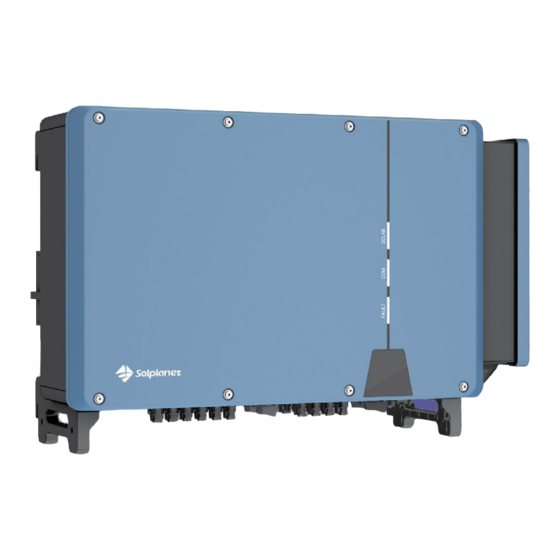
Page 10: Inverter Overview
4 Inverter overview 4.1 Product description Name Description Mounting ears Two ears hang the inverter onto the mounting-bracket. Fan assembly Maintain and replace the fan. Labels Warning symbols, nameplate, and QR code. Two handles, move the product and hang the inverter onto the Bottom handles mounting-bracket. -
Page 11: Dimensions
4.2 Dimensions Unit: mm 4.3 LED indicator The LED indicator can indicate the operation state of the inverter. LED indicator LED state Description The white LED is glowing when the product is operating Glowing normally. SOLAR The white LED is flashing when the product is self checking (White) Flashing automatically. -
Page 12: Circuit Diagram
4.5 Supported grid types The grid types supported by Solplanet is TN-S, TN-C,TN-C-S, TT, as shown in the figure below: For the TT grid structure, the effective value of the voltage between the neutral wire and the ground wire must be less than 20V. - Page 13 The smart meter that can be used with inverter product must be approved by Solplanet. For more information about the smart meter, please contact the local service team.
- Page 14 This product complies with IEC 62109-2 clause 13.9 for earth fault alarm monitoring. If an Earth Fault Alarm occurs, the red color LED indicator will illuminate. At the same time, the error code 38 will be sent to the Solplanet Cloud. (This function is only available in Australia and New Zealand).
-
Page 15: Communication Overview
4.7 Communication overview The communication overview with an Ai-dongle: The communication overview with a LTE Cat-1 stick: One Ai-dongle or LTE CAT-1 stick can connect with up to five devices: UM0030_ASW 75K-110K-LT_EN_V03_1023... - Page 16 The communication overview with Ai-Logger for a large PV plant: UM0030_ASW 75K-110K-LT_EN_V03_1023...
-
Page 17: Mounting
5 Mounting 5.1 Requirements for mounting DANGER Danger to life due to fire or explosion! Despite careful construction, electrical devices can cause fires. This can result in death or serious injury. Do not mount the product in areas containing highly flammable materials or gases. ... -
Page 18: Take Out The Product
Maintain the recommended clearances to other inverters or objects. In case of multiple inverters, ensure the appropriate clearance between the inverters. The product should be mounted such that the LED indicators can be viewed without difficulty. The DC switch of the product must always be readily accessible. ... - Page 19 5.3.1 Manual transport Step 1: Use the handles on the top and bottom of the enclosure to transport the inverter to the destination. Screw-in handles are optional. The product can be moved by them. 5.3.2 Hoisting transport Step 1: Screw the two lifting rings into the hangers of the inverter. Step 2:...
-
Page 20: Mounting
The lifting rings and the sling are not within the delivery scope. 5.4 Mounting CAUTION Damage to cable lines can cause personal injury! The walls may be covered with power cords or other lines (for example, gas or water). Make sure that no cables on the wall or inside the wall cavity are damaged when drilling. ... - Page 21 CAUTION Danger of personal injury due to falling inverter! If the hole depth and distance are not correct, the inverter may fall off the wall. Before inserting the bolts into the wall, measure the depth of the hole. Step 3: Clean the dust in the hole, plug 4 expansion bolts into the hole, fix them with a rubber hammer, and tighten the nuts with a wrench, fix the bolt tail, and remove the nut, spring washer and flat washer and reserve them for the next step.
- Page 22 Make sure that the four ears fit well with the groove. Step 7: Fix the inverter with screws. UM0030_ASW 75K-110K-LT_EN_V03_1023...
-
Page 23: Electrical Connection
6 Electrical connection 6.1 Overview of the connection area Item Name DC connector inputs 1-6(connected to DC switch 1) DC switch 1 DC connector inputs 13-16(connected to DC switch 3) DC switch 3 Ai-dongle port Reserved terminal AC cable - knockout seal Lock valve DC connector inputs 7-12(Connected to DC switch 2)... -
Page 24: Connecting Additional Grounding
6.2 Connecting additional grounding The inverter is equipped with a grounding fault monitoring device. The grounding fault monitoring device will disconnect the inverter from utility grid when it detects there is no ground conductor connected. Hence the product does not require additional grounding or equipotential bonding when operating. -
Page 25: Ac Connection
Step 3:Apply paint to the grounding terminal to ensure corrosion resistance. The grounding screws have been anchored to the side of the inverter before delivery, and do not need to be prepared. There are two grounding terminals. Use at least one of them to ground the inverter. 6.3 AC connection 6.3.1 Requirements for the AC connection Cable Requirements... - Page 26 Requirements for M12 OT/DT Terminal OT/DT terminals (not included in the delivery scope) are required for fixing AC cables to the terminal block. Purchase the OT/DT terminals according to the following requirements. Item Description a≤44mm 12.5mm≤b≤15.5mm C≤25mm Aluminium Cable Requirements If an aluminium cable is selected, use a copper to aluminium adapter terminal to avoid direct contact between the copper bar and the aluminium cable.
- Page 27 This is necessary, for example, in an IT system if there is no neutral conductor present and you intend to install the inverter between two line conductors. If you are uncertain about this, contact your grid operator or Solplanet.
- Page 28 Step 2: Remove the two screws from the wiring compartment using a torx screwdriver and open the wiring compartment. Step 3: Keep the wiring compartment opened during wiring through the limit lever attached to the cover. Step 4: Use a screwdriver to remove the waterproof ring at the bottom of the wiring compartment and store the removed screws properly.
- Page 29 Step 5: Cut the appropriate hole in the tower guard coil according to the selected AC wire outer diameter specification. Step 6: Lead the cable with the protective layer stripped through the waterproof ring. Step 7: Strip the protection layer and insulation layer by specific length, as described in the figure below. Step 8:...
- Page 30 Step 9: Secure the wires to corresponding terminals. Step 10: Reinstall the waterproof ring. UM0030_ASW 75K-110K-LT_EN_V03_1023...
- Page 31 If the PE cable is an independent single-core cable, inserted into the cabinet through the reserved grounding port. Step 11: Close the wiring compartment and tighten the two screws on the wiring compartment with a torx screwdriver. UM0030_ASW 75K-110K-LT_EN_V03_1023...
-
Page 32: Dc Connection
6.4 DC connection 6.4.1 Requirements for the DC connection Requirements for the PV modules per input: All PV modules should be of the same type. All PV modules should be aligned and tilted identically. On the coldest day based on statistical records, the open-circuit voltage of the PV array must never exceed the ... - Page 33 Cable requirements: Item Description Value Cable type PV cable External diameter 5-8 mm Conductor cross-section 2.5-6 mm² Number of copper strands At least 7 The rated voltage ≥1100 V Procedure: Step 1: Strip 12 mm off the cable insulation. Step 2: Insert the stripped cable into the DC connector up to the stop. Press the clamping bracket down until it audibly snaps into place.The stranded wire can be seen inside the clamping bracket chamber.
- Page 34 If the stranded wire is not visible in the chamber, the cable is not correctly inserted and the connector must be reassembled. To do this, the cable must be removed from the connector. Release the clamping bracket. To do so, insert a screwdriver (blade width: 3.5 mm) into the clamping bracket and pry the clamping bracket open.
- Page 35 Cable requirements: Item Description Value Cable type PV1-F,UL-ZKLA or USE2 External diameter 5-8 mm Conductor cross-section 2.5-6 mm² Number of copper strands At least 7 The rated voltage ≥1100 V Proceed as follows to assemble each DC connector. Step 1: Strip 12 mm off the cable insulation. Step 2:...
- Page 36 Step 4: Ensure that the cable is correctly positioned. 6.4.3 Connecting the PV array DANGER Danger to life due to high voltages in the inverter! When exposed to light, the PV modules generate high DC voltage which is present in the DC cables. Touching live DC cables may result in death or lethal injuries due to electric shock.
- Page 37 Step 3:Ensure that there is no ground fault in the PV array. Step 4:Check whether the DC connector has the correct polarity. If the DC connector is equipped with a DC cable having the wrong polarity, the DC connector must be reassembled. The DC cable must always have the same polarity as the DC connector.
- Page 38 Type 2 DC connector: Connect the assembled DC connectors to the inverter. Do not pull out the protective caps from unused DC input connectors. Check the positive and negative polarity of the PV strings, and connect the PV connectors to corresponding terminals only after ensuring polarity correctness.(The image below uses the type 2 connector as an example only.) Step 7:Ensure that all DC connectors and the DC connectors with sealing plugs are securely in place.
-
Page 39: Rs485 Cable Connection
6.5 RS485 cable connection NOTE Damage to the inverter due to electrostatic discharge. Internal components of the inverter can be irreparably damaged by electrostatic discharge. Ground yourself before touching any component. 6.5.1 Connection Procedure Step 1: Take out the relevant accessory from the package. Step 2:... - Page 40 Step 4: Strip the protection layer and insulation layer by specific length. Lock the shielded twisted-pair communication cable to the wiring terminal according to the sequence shown in the following figure, insert the wiring terminal into the sealing head, adjust the communication cable, insert the sealing ring, and lock the nut.
-
Page 41: Ai-Dongle Connection
6.5.2 Multi-inverter connection In case of multiple inverters, all the inverters can be connected via RS485 cables in a daisy chain configuration. The inverter has an impedance matching function of the 485 communication bus. If the communication bus needs to match the impedance, turn the DIP switch to the ON position. - Page 42 Step 3: Insert the wiring terminal into the sealing head, adjust the communication cable, insert the sealing ring, and lock nut. Step 4: Remove the dust and waterproof cover of the Ai-Dongle on the inverter and retain it. Step 5: Attach the Ai-Dongle to the connection port in place and tighten it into the port by hand with the nut in the modular.
- Page 43 NOTE Rotating the communication modular will damage the communication modular! The communication modular is protected by locking nuts to protect the reliability of the connection. If the body of the communication modular is rotated, the communication modular will be damaged. It can only be locked by a nut.
-
Page 44: Commissioning
Turn the DC switch of the inverter to the “ON” position. Set initial protection parameters via the Solplanet App. For details, please refer to “8.4 Create a plant”. Switch on the AC circuit breaker. If the irradiation and grid conditions meet the minimum thresholds, the inverter will operate normally. -
Page 45: Solplanet App
Procedure: Step 1: Open Solplanet App to enter the login screen, and tap “Don’t have an account” to enter the next screen. Step 2: The user groups “Business users” and “End user” need to be selected according to your identity, and tap “Next step”. - Page 46 Step 1 Step 2 Step 3 Step 4 Step 5 UM0030_ASW 75K-110K-LT_EN_V03_1023...
-
Page 47: Create A Plant
8.4 Create a plant Procedure: Step 1: Open Solplanet App to enter the login screen, enter the account name and password, and tap “Log in” to enter the next screen. Step 2: Tap the symbol “+” to enter the next screen, and tap “Create or Modify Plant”, then the camera of the smart device automatically turns on, and scan the QR code of the Wi-Fi stick to enter the next screen, tap “Create... - Page 48 Step 1 Step 2 UM0030_ASW 75K-110K-LT_EN_V03_1023...
- Page 49 Step 3 Step 4 Step 5 Step 6 UM0030_ASW 75K-110K-LT_EN_V03_1023...
- Page 50 Step 7 Step 8 Step 9 UM0030_ASW 75K-110K-LT_EN_V03_1023...
- Page 51 Step 10 Step 11 UM0030_ASW 75K-110K-LT_EN_V03_1023...
-
Page 52: Setting Parameters
8.5.1 Inverter configuration Solplanet’s products comply with local grid codes when leaving the factory. The grid code and the parameters according to the requirements of the installation site should still be checked and confirmed. Once configuration of the product is completed, the product will start operating automatically. - Page 53 8.5.2 Grid code settings For the Australia market, the inverter cannot be connected to the grid before the safety related area is set. Please select from Australia Region A/B/C to comply with AS/NZS 4777.2:2020, and contact your local electricity grid operator on which Region to select.
- Page 54 Step 1 Step 2 ○ ○ ○ ○ ○ ○ ○ ○ ○ ○ ○ Step 3 Step 4 UM0030_ASW 75K-110K-LT_EN_V03_1023...
- Page 55 Active power can increase at Active power can increase at a specific gradient once the a specific gradient once the voltage has returned to f voltage has returned to f reset reset Act. Power as a percentage of P , Linear Act.
- Page 56 Here, the Droop is different from the Droop S in section 3.7.2 of the standard EN 50549-1. ∆���� = × 100 The formula below should be used to manually configure the Droop S. (��������������������−����1)/�������� Droop S 8.5.2 Active power reduction at overvoltage P(U) There are five modes(Please refer to the following images)which can be chosen for this function and certain parameters can be configured according to the requirement of the local grid company.
- Page 57 ○ ○ ○ ○ ○ ○ ○ ○ ○ ○ ○ ○ Step 3 Step 4 Active power can increase at a Active power can increase at a specific gradient once the specific gradient once the voltage has returned to U voltage has returned to U reset reset...
- Page 58 Parameter Description Droop is defined as the active power as a percentage of P The active power will continuously move along the voltage characteristic curve Act. Power as a percentage of ○ in the voltage range of U to U start stop , Linear...
- Page 59 Step 1 Step 2 ○ ○ ○ ○ ○ Step 3 Step 4 Step 1: Tap“Reactive power settings”to enter to the next page. Step 2: Tap“Enable reactive power to choose the reactive power control mode and tap the left arrow to go back. Step 3:...
- Page 60 Table description Parameter Description ○ The active power as a percentage of P The displacement factor that is cosine of the phase angle between the ○ Cosφ fundamental components of the line to neutral point voltage and the respective current. ○...
- Page 61 Step 1: Tap “Reactive power settings” to enter to the next page. Step 2: Ttap “Enable reactive power” to choose the reactive power control mode and tap the left arrow to go back. Step 3: Tap “Q(U) curve settings” to enter to the next page. Step 4:...
- Page 62 Table description Parameter Description ○ The voltage as a percentage of U ○ The reactive power as a percentage of P ○ Phase Choose the over-excited or under-excited. The lock-in active power value that enables the automatic reactive power Activating power as a delivery mode.
-
Page 63: Decommissioning The Product
9 Decommissioning the product 9.1 Disconnecting the inverter from voltage sources Prior to performing any work on the product, always isolate it from all voltage sources as described in this section. Always adhere to the prescribed sequence. WARNING Danger to life due to electric shock from destruction of the measuring device due to overvoltage. Overvoltage can damage a measuring device and result in voltage being present in the enclosure of the measuring device. -
Page 64: Dismantling The Inverter
Step 6: Ensure that no voltage is present between the positive terminal and negative terminal at the DC inputs using a suitable measuring device. Step 7: Open the AC/COM cover junction box and use a multimeter to ensure that the AC wiring terminals isolated from an AC power source. -
Page 65: Technical Data
10 Technical data 10.1 AC/DC 10.1.1 ASW75K-LT/ASW80K-LT DC Input Type ASW75K-LT ASW80K-LT Maximum power of PV array 112500 Wp 120000 Wp 1100V Maximum in put voltage MPP voltage range 200-1000 V 460-850 V MPP voltage range at Pnom Rated input voltage... - Page 66 Power factor at rated power Adjustable displacement 0.8 inductive..0.8 c apacitiv e power factor Feed-in phase Connection phase Overvoltage category in accordance with IEC 60664-1 Efficiency Maximum efficiency 98,6% European weighted 98,1% efficiency The voltage range meets the requirements of the corresponding national grid code. The frequency range meets the requirements of the corresponding national grid code.
- Page 67 Inrush current <20% of nominal AC current for a maximum of 10ms Contribution to peak 330 A short-circuit current ip Initial short-circuit alternating current 158.8 A 174.7 A (Ik" first single period effective value) Short circuit current continuous [ms] 158.8 A 174.7 A (max output fault current) Recommended rated current of AC...
-
Page 68: General Data
10.2 General data General data ASW75K/80K/100K/110K-LT 984mm × 640mm ×330mm Width × he ight × dep th 85Kg Weight Topology Non-isolated -25℃…+60℃ Operating temperature range Allowable relative humidity 0% ... 100% range (non-condensing) Degree of protection for IP66 electronics in accordance with IEC 60529 Climatic category in accordance with IEC 60721... -
Page 69: Protective Device
10.3 Protective device Protective devices ASW75K/80K/100K/110K-LT DC reverse polarity Integrated protection Integrated DC isolator Ground fault monitoring Integrated AC short- circuit current Integrated capability All-pole sensitive residualcurrent Integrated monitoring unit Active anti-islanding Integrated protection PV string current monitoring Integrated DC current injection Integrated monitoring Low voltage ride through... -
Page 70: Troubleshooting
11 Troubleshooting When the PV system does not operate normally, we recommend the following solutions for quick troubleshooting. If an error occurs, the red LED will turn solid ON. The error code can be read from the Solplanet APP. Error code... - Page 71 PE wire connection fault Ensure the grounding connection of the inverter is connected and reliable. If this fault occurs often, contact Solplanet service. Contact Solplanet service if you encounter errors not listed in the table above. UM0030_ASW 75K-110K-LT_EN_V03_1023...
-
Page 72: Maintenance
12 Maintenance 12.1 Cleaning the contacts of the DC switch DANGER High voltage of PV string may cause life danger! If the DC connector is disconnected while the PV inverter is working, an electric arc may occur causing electric shock and burns. - Page 73 Fans inside the inverter are used to cool the inverter during operation. If the fans do not operate normally, the inverter may not be cooled down and inverter efficiency may decrease. Therefore, it is necessary to clean the dirty fans and replace the broken fans in time.
-
Page 74: Recycling And Disposal
When the customer needs warranty service during the warranty period, the customer must provide a copy of the invoice, factory warranty card, and ensure the electrical label of the inverter is legible. If these conditions are not met, Solplanet has the right to refuse to provide with the relevant warranty service. -
Page 75: Contact
16 Contact EMEA Service email: service.EMEA@solplanet.net APAC Service email: service.APAC@solplanet.net LATAM Service email: service.LATAM@solplanet.net AISWEI Pty Ltd. Hotline: +61 390 988 674 Add.: Level 40, 140 William Street, Melbourne VIC 3000, Australia AISWEI B.V. Hotline: +31 208 004 844 (Netherlands) +48 134 926 109 (Poland) Add.: Barbara Strozzilaan 101, 5e etage,kantoornummer 5.12, 1083HN Amsterdam, the Netherlands... - Page 76 UM0030_ASW 75K-110K-LT_EN_V03_1023...
Need help?
Do you have a question about the ASW75K-LT and is the answer not in the manual?
Questions and answers