
Subscribe to Our Youtube Channel
Related Manuals for Vetter ManuTel


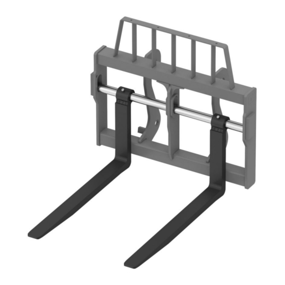
Summary of Contents for Vetter ManuTel
- Page 1 Operation manual Fork carrier with fork arms Read this manual prior to performing any task! Keep for future use! U163-530-US...
- Page 2 Fork carrier with fork arms...
- Page 3 This operating manual (hereinafter also referred to as “manual”) contains fundamental safety instructions for handling fork carriers with hook or shaft suspension as well as information about the fork arms of VETTER Forks, Inc. Incorrect use of the fork carrier and fork arms can result in serious injuries and even death.
-
Page 4: Table Of Contents
Table of contents TABLE OF CONTENTS OVERVIEW OF THE FORK CARRIER Range of application Designs SAFETY Symbols in this manual Intended use Operator obligations Dangers associated with handling the fork carrier and the fork arms Safety markings Personnel requirements 2.6.1 Qualifications 2.6.2 Unauthorized persons... - Page 5 Table of contents Replacing the fork arms Repairs and spare parts After completion of maintenance work TROUBLESHOOTING TECHNICAL DATA INDEX Fork carrier with fork arms...
-
Page 6: Overview Of The Fork Carrier
Scope This manual relates to both fork carrier types described (hook-on and shaft suspen- sion) in conjunction with VETTER fork arms. With regard to specific VETTER fork arms ® (e.g., VETTER SmartFork , VETTER folding fork arms or VETTER ManuTel fork arms), always observe the operating manual provided. -
Page 7: Safety
Safety Intended use Safety Symbols in this manual Safety instructions Safety instructions in this manual are marked by symbols. The safety instructions are introduced by signal words which express the extent of the danger. DANGER indicates a hazardous situation which, if not avoided, will result in L DANGER death or serious injury. - Page 8 Safety Intended use Risk of injury from incorrect use! L WARNING – Never neglect the general requirements for safety and due diligence. If in doubt, personally ensure that there are no people or obstacles in the danger zone of the carrier vehicle. –...
-
Page 9: Operator Obligations
Safety Operator obligations Operator obligations Operator The operator is the person who operates the fork carrier (with or without fork arms) on an carrier vehicle for industrial or commercial purposes, or who delegates use to a third party and bears the legal product responsibility during operation for the protection of personnel or third parties. -
Page 10: Dangers Associated With Handling The Fork Carrier And The Fork Arms
Safety Dangers associated with handling the fork carrier and the fork arms Dangers associated with handling the fork carrier and the fork arms Incompatibility Danger to life from the use of incorrect components! L WARNING – Only mount fork carriers on designated, exactly suitable carrier vehicle sus- pension. -
Page 11: Safety Markings
Safety Safety markings Incorrect loading Danger to life due to incorrectly lifted load! L WARNING – Always observe the load and load center distance of the load and use the load charts for the carrier vehicle and the fork arms to compare them. –... - Page 12 Safety Safety markings Fig. 1: Fork carrier type plate Article/serial number Dead weight Maximum permissible load Center of gravity Year of manufacture Load center - distance from fork back The use of the fork carrier without the prescribed type plate is considered incor- NOTICE rect use.
- Page 13 Safety Safety markings Hard stamping The hard stamping identifies (via the article number it contains) the version of the fork arm upon delivery. Fork arms without a marking must not be put into operation. The hard stamping of the fork arm is located on the fork back at the side (Fig. 2). The use of the fork arms without the prescribed markings is considered incor- NOTICE rect use.
-
Page 14: Personnel Requirements
Safety Personnel requirements > Qualifications Personnel requirements 2.6.1 Qualifications Risk of injury if personnel are not sufficiently qualified! L WARNING – Have all tasks carried out by personnel qualified to do so without exception. – Keep unqualified personnel away from the danger zones. If unqualified personnel perform work on the system or remain in the danger zone of the system, dangers arise that could cause serious injuries and signifi- cant material damage. -
Page 15: Unauthorized Persons
Safety Personal protective equipment 2.6.2 Unauthorized persons Danger to life for unauthorized persons due to dangers in the danger and work L WARNING area! – Keep unauthorized persons away from the danger and work area. – If in doubt, speak to these persons and tell them to leave the danger and work area. -
Page 16: Protection Of The Environment And Disposal
Safety Protection of the environment and disposal Protective clothing Protective clothing is close-fitting, with low resistance to tearing, with narrow sleeves and without protruding parts. Protective gloves Protective gloves are used to protect hands from friction, abrasions, punctures and deeper injuries. They also offer protection in the event of contact with hot surfaces. Safety shoes Safety shoes protect the feet against crushing, falling components and slipping on slip- pery floor surfaces. - Page 17 Safety Protection of the environment and disposal General disposal If there is no take-back agreement or disposal agreement in place, separate compo- instructions nents by material and send them for recycling: Sort and dispose of the other components according to their material characteris- tics.
-
Page 18: Structure
Structure Structure of hook-type suspension Structure Structure of hook-type suspension Example of design A Fig. 3: Fork carrier, example of design A Upper suspension for tool change device Contact surface Lock borehole for tool change device Locking screw Type plate Hook profile for ITA/square-hook forks Fork carrier with fork arms... - Page 19 Structure Structure of hook-type suspension Example of design B Fig. 4: Fork carrier, example of design B Contact surface Lock borehole for tool change device Upper suspension for tool change device Locking screw Type plate Hook profile for ITA/square-hook forks Fork carrier with fork arms...
-
Page 20: Structure Of Shaft-Type Suspension
Structure Structure of shaft-type suspension Structure of shaft-type suspension Fig. 5: Fork carrier, shaft suspension Upper suspension for tool change device Shaft suspension for shaft forks Lock borehole for tool change device Contact surface Safeguarding device (plate and 2 screws) Type plate Fork carrier with fork arms... -
Page 21: Fork Arm
Structure Fork arm Fork arm Fig. 6: Structure of the fork arm Fork head Upper hook Fork back 10 + 11 Suspension Fork bend Back height Fork thickness (GD) Locking pin Fork blade Spring 4 x 6 Cross section Lever Fork width (GB) Roll pin Taper... -
Page 22: Assembly
Assembly Fork arms with hook suspension Assembly Assembly site free of potentially explosive atmosphere! Never assemble or disassemble the fork carrier and fork arms inside potentially explo- sive atmospheres. Fork carrier Personnel: Driver of carrier vehicles Protective equipment: Protective clothing Industrial hard hat Protective gloves Safety shoes... - Page 23 Assembly Fork arms with hook suspension Assembly Assemble the fork arms on the fork carrier in the following order: Prepare the lifting device for large loads, e.g., indoor crane and lifting straps. The work must be carried out by 2 people. Move the fork carrier to the vertical position and move it to a height that allows for safe and comfortable assembly of the fork arms.
- Page 24 Assembly Fork arms with hook suspension Fig. 8: Pushing the fork arm onto the fork carrier L WARNING! Risk of hands and other body parts being crushed when aligning and pushing on! Grip the fork arm at the head and fork blade with someone else to assist you and carefully slide it onto the fork carrier from the outside using appropriate force (Fig.
-
Page 25: Fork Arms With Shaft Suspension
Assembly Fork arms with shaft suspension Fork arms with shaft suspension Personnel: Driver of carrier vehicles Protective equipment: Protective clothing Industrial hard hat Protective gloves Safety shoes Disassembly Ä Chapter 6.6 “Replacing the fork arms” Proper disassembly is described under on page 43. - Page 26 Assembly Fork arms with shaft suspension Fig. 9: Installing the shaft forks L WARNING! Risk of hands and other body parts being crushed when aligning and pushing on! Push the shaft through the outer elongated hole, the socket of the fork arm, and the middle elongated hole from the side.
-
Page 27: Operation
Operation Adjusting the distance between the fork arms Operation Adjusting the distance between the fork arms Personnel: Driver of carrier vehicles Protective equipment: Protective clothing Industrial hard hat Protective gloves Safety shoes Distance between the fork arms Set the distance between the fork arms in such a way that the load can be lifted safely. To do so, space the fork arms equally from the middle of the vehicle and lock them in position. - Page 28 Operation Adjusting the distance between the fork arms L WARNING! Risk of crush injuries to hands when closing the locking device! Close the locking device of the fork arms. When doing so, ensure your fingers are not in the danger zone and flip the lever again using appropriate force. Check that the fork arms are locked into the locking groove (Fig.
- Page 29 Operation Adjusting the distance between the fork arms If the position is to be fixed, fix both shaft fork arms in place on the shaft horizon- tally by tightening the screw connection at the adjusting rings or by using the locking screws (available in the scope of delivery depending on the configuration, not shown here).
-
Page 30: Maintenance
Maintenance Maintenance activities > Daily visual inspection performed by the driver Maintenance Maintenance intervals Routine maintenance Routine maintenance must be performed in order to ensure safe and fault-free opera- tion of fork carriers and fork arms. Interval Maintenance work Personnel daily Visual inspection performed by the driver Ä... -
Page 31: Checking The Fork Carrier
Maintenance Checking the fork carrier Hazard prevention at the workplace Danger to life due to unsecured vehicle or moving parts! L WARNING Always note the following prior to any maintenance measure: – Secure the carrier vehicle to prevent it from rolling away inadvertently. –... -
Page 32: Checking The Fork Arms
Maintenance Checking the fork arms > Checking the locking device and safeguarding device In addition, always observe the following: – Check the fork carrier for any permanent deformation at regular intervals. Immedi- ately prevent further use of deformed fork carriers and have them checked by a trained service specialist. -
Page 33: Checking The Suspension
Maintenance Checking the fork arms > Checking the suspension Hook suspension locking device Risk of injury from a defective locking device! L WARNING – Replace damaged locking devices immediately. – If the locking device is missing, it must be replaced before commissioning. –... - Page 34 Maintenance Checking the fork arms > Checking the suspension Damage to the hooks Danger to life due to damaged fork hooks! L WARNING Always observe the following: – Check the upper and lower hook for cracks, deformation, and wear. – Check the upper hook particularly in the area below the weld. Ä...
- Page 35 Maintenance Checking the fork arms > Checking the suspension Mount the fork arm on the fork carrier and close the locking device. Fig. 12: Upward bending of the hook (view from above) Use a measuring tool (e.g., feeler gage) to measure the gap between the block of the locking device and the head of the fork arm (Fig.
-
Page 36: Crack Test For Fork Arms
Maintenance Checking the fork arms > Deformation of the fork arms Fig. 13: Shaft fork arm suspension To ensure a reliable check, first dismantle Ä Chapter 6.6 “Replacing the fork arms” Ä Chapter 6.5 “Cleaning the fork carrier and fork arms” on page 43 and clean on page 42 the shaft fork arm. - Page 37 Maintenance Checking the fork arms > Deformation of the fork arms Bending of the blade Personnel: Service specialist Protective equipment: Protective clothing Industrial hard hat Protective gloves Safety shoes Special tool: Ruler Bent fork blade Danger to life due to bent fork arms! L WARNING –...
- Page 38 Maintenance Checking the fork arms > Deformation of the fork arms Measure the difference k between the ruler and fork blade at the edge of the fork tip. If the measured difference k (Fig. 14) exceeds the maximum permissible bend kmax, immediately ban any further use of the fork arm.
- Page 39 Maintenance Checking the fork arms > Deformation of the fork arms Mark (e.g., using a pencil) the distance from the fork bend horizontally and verti- cally at 19.69 inches (500 mm) without cracks. Fig. 15: Angularity of the fork arm Measure diagonal dimension d between both markings (Fig.
- Page 40 Maintenance Checking the fork arms > Deformation of the fork arms Deformed fork arms Danger to life due to deformed fork arms! L WARNING – Check the fork arms for deformation on a regular basis. – Never use fork arms that exceed the maximum permissible height difference. A difference in height between the fork tips of the mounted fork arms indicates deformation of the fork blade or that a fork arm has bent upwards.
-
Page 41: Wear On The Fork Arms
Maintenance Checking the fork arms > Wear on the fork arms Always observe the following: NOTICE – If the fork arms are too severely damaged or worn, do not use them any fur- ther and replace them in pairs. Damaged and worn fork tips (Fig. 17) are an injury risk or could damage the goods to be transported. -
Page 42: Cleaning The Fork Carrier And Fork Arms
Maintenance Cleaning the fork carrier and fork arms Conduct the measurement as follows: Have the values for the thickness of the fork arm on delivery to hand for compar- ison purposes. Fig. 18: Areas with increased wear Wear area, fork bend Wear area, fork tip Use a caliper gage to measure the thickness of the fork arm. -
Page 43: Replacing The Fork Arms
Maintenance Replacing the fork arms Replacing the fork arms Personnel: Driver of carrier vehicles Protective equipment: Protective clothing Industrial hard hat Protective gloves Safety shoes Danger when replacing only one fork arm! NOTICE – If one fork arm is damaged, always replace the fork arms in pairs. If one fork arm is damaged, it is to be expected that the other arm has, or will have, the same damage. - Page 44 Maintenance Replacing the fork arms Fig. 19: Pushing the fork arm down from the fork carrier L WARNING! Risk of hands and other body parts being crushed when pushing down! Grip the fork arm at the head and fork blade with someone else to assist you and push it down from the fork carrier with appropriate force (Fig.
- Page 45 Maintenance Replacing the fork arms Fork arms with shaft suspension Have a lifting device available for large loads, e.g., indoor crane. The work must be carried out by 2 people. Align the fork arms so that it is parallel with the ground. Place the fork arms on the ground with minimal contact by lowering the fork car- rier.
-
Page 46: Repairs And Spare Parts
Maintenance After completion of maintenance work Repairs and spare parts Repairs Loss of functionality due to incorrect repairs! NOTICE – Always use genuine components. – Observe the safety instructions in the relevant separate instructions. Incorrect repairs or the use of third-party components could lead to damage and a loss of functionality. -
Page 47: Troubleshooting
Troubleshooting Troubleshooting Should you have any technical difficulties or questions, contact customer service Ä “Customer service” on page 3. Fork carrier with fork arms... -
Page 48: Technical Data
Technical data Technical data Fig. 21: Dimensions A Total width of fork carrier (inches) B Working width of fork carrier (inches) Fork carrier with fork arms... - Page 49 Technical data Fig. 22: Rated load capacity C Load capacity of fork arms (lbs/pair) D For load center distance LC (inches) Fork carrier with fork arms...
-
Page 50: Index
Index INDEX Angularity ....... . 38 Incompatibility ......10 Applicable documents . - Page 51 Index Shaft fork arm locking device ....25, 28 Spacing Hook-on fork arm ..... . . 27 Shaft fork arm .
- Page 53 Deviations and changes are part of our ongoing review and improvement of the product. VETTER Industrie GmbH does not accept any responsibility or liability for errors that arise from the use and application of this document. This document, including all parts, is protected by copyright.
Need help?
Do you have a question about the ManuTel and is the answer not in the manual?
Questions and answers