Digikeijs DR4018 Instruction Manual
Switching decoder
Hide thumbs
Also See for DR4018:
- Instruction manual (37 pages) ,
- Manual (44 pages) ,
- Instruction manual (36 pages)
Advertisement
Quick Links
DR4018 Switch decoder
DR4018
Switching Decoder
Instruction Manual
© Copyright 2005 – 2021 Digikeijs, the Netherlands. All
rights reserved. No information, images or any part of
this document may be copied without the prior written
permission of Digikeijs.
www.digikeijs.com
*R-Bus, B-Bus are registered trademarks of Modelleisenbhan GmbH. XpressNet and RS-Bus are registered trademarks of Lenz
1
Advertisement

Related Manuals for Digikeijs DR4018


Summary of Contents for Digikeijs DR4018
- Page 1 DR4018 Switch decoder DR4018 Switching Decoder Instruction Manual © Copyright 2005 – 2021 Digikeijs, the Netherlands. All rights reserved. No information, images or any part of this document may be copied without the prior written permission of Digikeijs. www.digikeijs.com *R-Bus, B-Bus are registered trademarks of Modelleisenbhan GmbH. XpressNet and RS-Bus are registered trademarks of Lenz...
-
Page 2: General Information
(programming track) Signal patterns of the integrated signal decoders Special feature CV programming for control panels which switch off the programming track Resetting the DR4018 to factory settings for Control panels which switch off the programming track Programming examples with different... -
Page 3: Warranty And Warranty Conditions
We reserve the right to change the design of the product, software and/or firmware without prior notice. copyright All Digikeijs manuals and other written instructions supplied and/or downloadable are copyrighted. Duplication is not permitted without the written permission of Digikeijs. -
Page 4: Technical Specifications
2.1 General product information The DR4018 is a multiprotocol decoder that automatically detects DCC and MM. A rectifier is installed in the decoder so that the outputs always switch with DC voltage (DC). With the function mapping via CV programming it is possible to realize all imaginable tasks. -
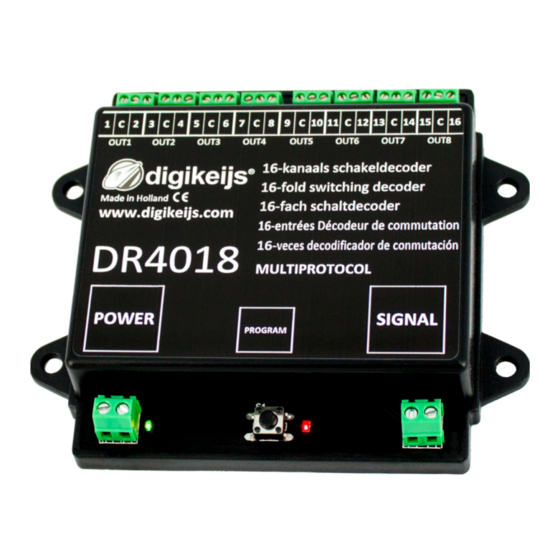
Page 5: Hardware Overview
DR4018 Switch decoder 2.3 Hardware Overview Connection Out 1 1 = - Power Connection C = + Recommendation min. 12V DC 3A Green Connection Out 2 3 = - Display Supply voltage present C = + 11 programming button Connection Out 3 5 = -... - Page 6 To read CV's on the programming track, the POWER and SIGNAL connections must be connected to the programming track of the central unit. In this case, please disconnect the external power supply at the DR4018. In addition, a resistor (150-270 Ohm) should be connected to "C" and terminal 1 of Out 1, otherwise no read confirmation can be detected by the central unit.
- Page 7 The turnout addresses are always assigned by a turnout command!!! Make sure the DR4018 is powered from the decoder's power connector. It is best to use a switching power supply with at least 12V DC output voltage and 3A output power. The signal connection of the decoder must be connected to the main track output of your control panel! Call up the desired magnetic article address which the DR4018 is to receive as the start address at the central unit, handset controller, app, etc.
- Page 8 (For further information on CV byte or CV bit programming, please refer to the operating instructions of your control panel) Now the desired CV value can be written to the DR4018 with the respective function Write POM of the central, app or handset controller.
- Page 9 Please note that reading out and programming the DR4018 via the programming track only works if the central unit does not switch off the programming track! Therefore, before attempting programming, check that the green LED next to the power connector is lit. Only if this is the case can the DR4018 be successfully pro- grammed as described in this section.
- Page 10 Switch the function F0 (light) on and off again to activate the locomotive in the control panel. Press the programming button on the DR4018. The red LED now lights up continuously and indicates that the DR4018 is in "programming mode".
- Page 11 Please note that reading out and programming the DR4018 via the programming track only works if the central unit does not switch off the programming track! Therefore, before attempting programming, check that the green LED next to the power connector is lit. Only if this is the case can the DR4018 be successfully pro- grammed as described in this section.
- Page 12 DR4018 indicates whether the programming track always outputs volt- age. If this does not light up continuously, the programming track is switched off. This leads to the DR4018 requiring a different programming or re- setting procedure than usual.
- Page 13 This is absolutely necessary to successfully complete the RESET. After approx. 30 seconds the desired connection can be restored. The DR4018 is now reset to factory settings. The POM address was reset to 9999 again and the DR4018 has the magnetic article address 1 again. By switching the mag- netic article address 1 it can be checked whether the RESET was successful.
- Page 14 DR4018 Switch decoder 4.0 Programming examples with different Control Panels Please note that it is impossible to create individual programming instructions for all control panels. On the following pages only an overview of the procedure is possible. www.digikeijs.com *R-Bus, B-Bus are registered trademarks of Modelleisenbhan GmbH. XpressNet and RS-Bus are registered trademarks of Lenz...
- Page 15 Press the programming button on the DR4018 once. The red LED lights up. Press the switch symbol once. The red LED on the DR4018 extinguishes and the switched turnout address is stored as start address (OUT1). Please also note point 3.1 of this manual! www.digikeijs.com...
- Page 16 The red LED lights up. Press the "Program" key in the Z21® App. Press the programming button on the DR4018 once. The red LED goes out. The DR4018 will now save and accept the settings you have made. The changes to the programmed settings are immediately active.
- Page 17 DR4018 Switch decoder 4.3 ROCO® Multi-mouse programming example Program start address Programming the start address (OUT1) Verbinden Sie den DR4018 mit dem 'Main Track' /'Track out' Ihrer Multimaus. Wählen Sie die gewünschte Weichenadresse aus die der DR4018 als Startadresse kommen soll.
- Page 18 4.4 ROCO® Multi-mouse POM Programming example CV programming via POM (Program On Main) Connect the DR4018 to the 'Main Track' / 'Track out' of your multi mouse. Create a new locomotive in the Multimause with locomotive address 9999 Enter a locomotive name e.g. "LOK1". Then press "OK".
- Page 19 The red LED lights up. You can now send the programming command by pressing 'OK' again. To exit the programming mode, press the programming button on the DR4018 again. The red LED goes out and the changes are saved. Please also note point 3.1 of this manual! www.digikeijs.com...
- Page 20 Press the programming button on the DR4018 once. The red LED lights up. Switch the desired address on your Intellibox® once. The red LED on the DR4018 goes out as soon as the module has received the correct address. Please also note point 3.1 of this manual! www.digikeijs.com...
- Page 21 DR4018 Switch decoder 4.6 Uhlenbrock® Intellibox® POM Programming example CV programming via POM (Program On Main) Connect the DR4018 to the main track of your Intellibox®. Program- Set the Intellibox to the "Programming Mode" by pressing the [mode] key. Until "programming mode" appears on the display.
- Page 22 DR4018 Switch decoder Lok#9999: Press the [Enter] key to send the desired CV value to the DR4018. To exit the programming mode, press the programming button on the DR4018. The red LED goes out and the changes are saved. Please also note point 3.1 of this manual! www.digikeijs.com...
- Page 23 4.7 LENZ® Programming example Program start address Programming the start address (OUT1) Connect the DR4018 to the J and K output (main track) of your LZV100 central station. Press [F] until [* B&W *] appears on the LH100 screen. Then press [ENTER].
- Page 24 DR4018 Switch decoder 4.8 LENZ® POM Programming example CV programming via POM (Programm On Main) Connect the DR4018 to the J and K outputs (main track) of your LZV100 central. Press the [ CI ] key and enter the locomotive address '9999'.
- Page 25 DR4018 Switch decoder To exit the programming mode, press the programming button of the DR4018 again. The red LED goes out and the changes are saved. Please also note point 3.1 of this manual! www.digikeijs.com *R-Bus, B-Bus are registered trademarks of Modelleisenbhan GmbH. XpressNet and RS-Bus are registered trademarks of Lenz...
- Page 26 5.1 The red LED goes out again although the programming button has not been pressed again. Some central units have the problem that after pressing the programming button of the DR4018, the red LED goes out again shortly after the program- ming mode has been activated and the DR4018 automatically terminates the programming mode.
- Page 27 DR4018 Switch decoder 6.0 Connection examples 6.1 Connection options Power and signal Connection Supply voltage Signal Connection to main track 12-18V DC/AC Power Connection to an external power supply Recommended Recommended for normal operation and for the POM programming Signal...
- Page 28 DR4018 Switch decoder 6.2 Connection examples with different presets (Preset CV47) The DR4018 can be easily parameterized for various switching tasks using the presets. These default settings are always made in CV 47. 0 1 2 3 6 13 PRESET 0...
- Page 29 DR4018 Switch decoder PRESET 7 PRESET 8 PRESET 11 DR4103 PRESET 9 PRESET 10 www.digikeijs.com *R-Bus, B-Bus are registered trademarks of Modelleisenbhan GmbH. XpressNet and RS-Bus are registered trademarks of Lenz...
- Page 30 DR4018 Switch decoder 7.0 CV Table CV CV Definition Range Value Decoder Version Manufacturer ID value '8' resets the decoder to factory settings. Long address high byte 192-255 Long address low byte 0-255 Configuration Data Bit Function Standard Value "0" = one-byte addressing (address in CV1), "1" = two-byte addressing “0”...
- Page 31 0 – 13 (This CV can only be written. Reading is not possible!) The DR4018 switching decoder has 13 possible presets to make programming easier. Of course, the individual CVs of the presets can also be adjusted individually. Number of addres-...
- Page 32 DR4018 Switch decoder CV Definition Range Value Dark time between the different signal transitions (only for DB signals) 1-255 Values for dimming the signals (night mode) 0-15 PWM period The resolution with which the internal PWM works to achieve effects and dimming values.
- Page 33 DR4018 Switch decoder CV Definition Range Value Output configuration Output 6 (See CV113 for Configuration) 0-255 Output configuration Output 7 (See CV113 for Configuration) 0-255 Output configuration Output 8 (See CV113 for Configuration) 0-255 Output configuration Output 9 (See CV113 for Configuration)
- Page 34 7.1 Vector groups Function mapping The following table shows how you can link the various outputs of the DR4018 module (1-16) with the turnout control panel of your control panel. This can be useful if you want to switch several outputs simultaneously via one key. If you want to switch several outputs in a group with one function key, then add the values.
- Page 35 IThis table shows how the different signal numbers (CV 131-134) are connected to output groups. It may be necessary to change this setting if you want to control turnouts and signals with the same DR4018. These CVs usually contain the value 0.
- Page 36 DR4018 Switch decoder 7.4 Signal patterns of the integrated signal decoders (CV131-134) The integrated signal decoder always uses a group of 4 addresses per signal. The combination of the first three addresses results in the signal pattern. In order to be able to call up the respective signal pattern, the first three addresses must therefore always be connected together.
Need help?
Do you have a question about the DR4018 and is the answer not in the manual?
Questions and answers