Table of Contents
Advertisement
Quick Links
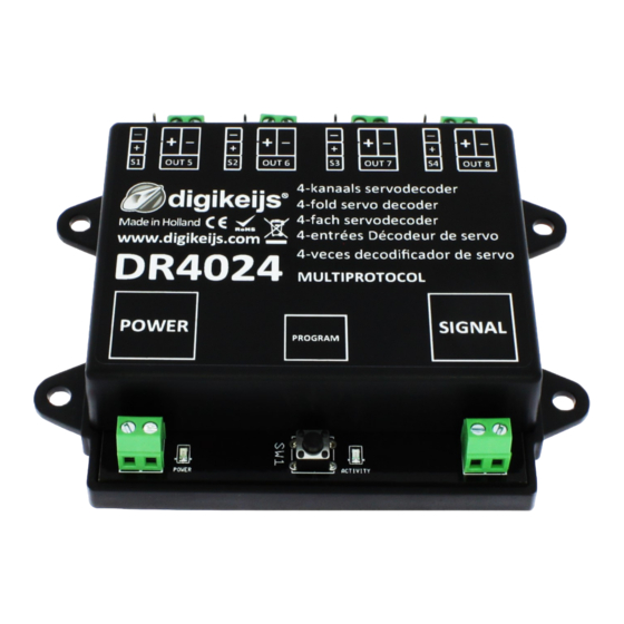
DR4024 servo decoder
DR4024
servo decoder
Instruction manual
© Copyright 2005 – 2021 Digikeijs, the Netherlands. All
rights reserved. No information, images or any part of
this document may be copied without the prior written
permission of Digikeijs.
1
www.digikeijs.com
*R-Bus, B-Bus are registered trademarks of Modelleisenbhan GmbH. XpressNet and RS-Bus are registered trademarks of Lenz
Advertisement
Table of Contents

Related Manuals for Digikeijs DR4024


Summary of Contents for Digikeijs DR4024
- Page 1 DR4024 servo decoder DR4024 servo decoder Instruction manual © Copyright 2005 – 2021 Digikeijs, the Netherlands. All rights reserved. No information, images or any part of this document may be copied without the prior written permission of Digikeijs. www.digikeijs.com *R-Bus, B-Bus are registered trademarks of Modelleisenbhan GmbH. XpressNet and RS-Bus are registered trademarks of Lenz...
-
Page 2: Table Of Contents
Special feature CV programming for control panels which switch off the programming track Please note! Resetting the DR4024 to factory settings for Control panels which switch off the This manual contains currently only the basic information and will be extended programming track step by step. -
Page 3: Warranty And Warranty Conditions
We reserve the right to change the design of the product, software and/or firmware without prior notice. Copyright All Digikeijs manuals and other written instructions that are supplied and/or downloaded are protected by copyright. Duplication is not permitted without written permission from Digikeijs. -
Page 4: Product Overview
With the function mapping via CV programming it is possible to realize all imaginable tasks. The DR4024 is a servo decoder with four servo outputs. Each servo output can be programmed to move to four different positions. The DR4024 also has four additional switching outputs which can be used, for exam- ple, for switch polarization or for controlling St. -
Page 5: Hardware Overview
DR4024 servo decoder 2.3 Hardware Overview Connection S1 Servo 1 (Output 1) Connection Out 5 (Output 5) Connection S2 Servo 2 (Output 2) Connection Out 6 (Output 6) Connection S3 Servo 3 (Output 3) Connection Out 7 (Output 7) Connection S4 Servo 4 (Output 4) -
Page 6: Programming
DR4024 servo decoder 3.0 Programming If the power input and the signal input of the DR4024 are connected to each other and are connected to the siding of the control unit, the control unit may shut down due to overload. -
Page 7: Programming The Magnetic Article Address
The turnout addresses are always assigned by a turnout command!!! Make sure the DR4024 is powered from the decoder's power connector. It is best to use a switching power supply with at least 12V DC output voltage and 2A output power. The signal connection of the decoder must be connected to the main track output of your control panel! Call up the desired magnetic article address which the DR4024 is to receive as the start address at the central unit, handset controller, app, etc. -
Page 8: Programming The Servo Positions A-D
3.2 Programming the servo positions A-D Make sure the DR4024 is powered from the decoder's power connector. It is best to use a switching power supply with at least 12V DC output voltage and 2A output power. The signal connector of the DR4024 must be connected to the main track output of your control panel! A locomotive with address 9999 and 128 speed steps DCC must be defined in the central unit, multi mouse, app etc.. -
Page 9: Programming Cv's Via Pom (Main Track Programming)
(For further information on CV byte or CV bit programming, please refer to the operating instructions of your control panel) Now the desired CV value can be written to the DR4024 with the respective function Write POM of the central, app or handset controller. -
Page 10: Programming Cvs On The Programming Track
Please note that reading out and programming the DR4024 via the programming track only works if the central unit does not switch off the programming track! Therefore, before attempting programming, check that the green LED next to the power connector is lit. Only if this is the case can the DR4024 be successfully programmed as described in this section. -
Page 11: Resetting The Dr4024 To Factory Defaults (Main Track Pom Programming)
Switch the function F0 (light) on and off again to activate the locomotive in the control panel. Press the programming button on the DR4024. The red LED now lights up continuously and indicates that the DR4024 is in "programming mode". -
Page 12: Resetting The Dr4024 To Factory Defaults (Programming Track)
Please note that reading out and programming the DR4024 via the programming track only works if the central unit does not switch off the programming track! Therefore, before attempting programming, check that the green LED next to the power connector is lit. Only if this is the case can the DR4024 be successfully programmed as de- scribed in this section. -
Page 13: Special Feature Cv Programming For Control Panels
LED next to the power connector of the DR4024 indicates whether the programming track always outputs voltage. If this does not light up continuously, the programming track is switched off. This leads to the DR4024 requiring a different programming or resetting procedure than usual. - Page 14 This is absolutely necessary to successfully complete the RESET. After approx. 30 seconds the desired connection can be restored. The DR4024 is now reset to factory settings. The POM address was reset to 9999 again and the DR4024 has the magnetic article address 1 again. By switch- ing the magnetic article address 1 it can be checked whether the RESET was successful.
-
Page 15: Troubleshooting
Some central units have the problem that after pressing the programming button of the DR4024, the red LED goes out again shortly after the programming mode has been activated and the DR4024 automatically terminates the programming mode. -
Page 16: Connection Examples
DR4024 servo decoder 5.0 Connection examples 5.1 Connection options Power and signal Connection Supply voltage Signal Connection to main track 12-18V DC/AC Power Connection to an external power supply Recommended min. 12V DC 2A Recommended for normal operation and for the POM... -
Page 17: Connection Dr4102 Relay Switch Polarization
DR4024 servo decoder 5.2 Connection DR4102 relay switch polarization + DC Important! Be sure to observe the polarity (+ and - ) of the DR4102! An incorrect connection will destroy the Out x switching output on the DR4024! DR4024 PRESET 1 www.digikeijs.com... -
Page 18: Enclosed Level Crossing With Flasher
DR4024 servo decoder 5.3 Railway crossing with barrier and interchangeable indicators 5.4 Wing signal NL www.digikeijs.com *R-Bus, B-Bus are registered trademarks of Modelleisenbhan GmbH. XpressNet and RS-Bus are registered trademarks of Lenz... -
Page 19: Index 2 6.0 Servo Installation And Connection
DR4024 servo decoder 6.0 Servo installation and connection • Servo connection cables should always be kept as short as possible to avoid interference. • With long servo cables, always use twisted connection cables with a cross-section of at least 0.35 mm² to minimize interference. -
Page 20: General Information 2 7.0 Cv Table
(this CV can only be written a read out is not possible!) The DR4024 servo decoder has four presets to make programming easier. Each preset configures the DR4020 so that you do not have to change CVs manually. For detailed information on these presets, see page 24. - Page 21 DR4024 servo decoder CV Definition Range Value 117 CVs 117-120 each have the same function as switching outputs 1-4. 0-179 Switching output 1 (OUT 5) Bits 0-1 sets the switching point for the 'on' position of the assigned switching output.
- Page 22 DR4024 servo decoder CV Definition Range Value Position A for Servo 2 0-255 Position C for Servo 2 0-255 Position B for Servo 2 0-255 Position D for Servo 2 0-255 Position A for Servo 3 0-255 Position C for Servo 3...
-
Page 23: Index 2 7.1 Function Mapping
7.1 Funktions Mapping The following table shows you how to connect the different outputs of the DR4024 module (1-8) to the turnout control panel of your control panel ver- knüpfen´werden. This can be useful if you want to switch several outputs simultaneously via one key. If you want to switch several outputs in a group with one function key, then add the values. - Page 24 DR4024 servo decoder 7.2 Presets (Preset 1-4) There are four preset CV sets to make programming easier. These presets are called with the CV47. The setting in CV47 automatically sets some default effects and settings. It is not possible to read the CV 47.
- Page 25 DR4024 servo decoder Default setting 3 (Preset 3) Level crossing with changeable indicators, two barriers and mass simulation Let your imagination run wild by using the presets as a starting point on which to build other effects. For example, you can use preset 2 as the basis for a signal that influences the behavior of the locomotive: Adjust the function mapping so that the outputs switch together with the servos and set the output configura- tion so that it switches when the green mode is reached.
Need help?
Do you have a question about the DR4024 and is the answer not in the manual?
Questions and answers