Sign In
Upload
Download
Table of Contents
Contents
Add to my manuals
Delete from my manuals
Share
URL of this page:
HTML Link:
Bookmark this page
Add
Manual will be automatically added to "My Manuals"
Print this page
×
Bookmark added
×
Added to my manuals
Manuals
Brands
Fisher & Paykel Manuals
Oven
OB60BCEW1
Service manual
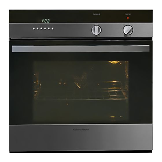
Fisher & Paykel OB60BCEW1 Service Manual
Hide thumbs
1
2
3
Table Of Contents
4
5
6
7
8
9
10
11
12
13
14
15
16
17
18
19
20
21
22
23
24
25
26
27
28
29
30
31
32
33
34
35
36
37
38
39
40
41
page
of
41
Go
/
41
Contents
Table of Contents
Bookmarks
Table of Contents
Table of Contents
Specifications
Model Descriptions
Electrical Ratings
Serial Label
Installation
Cabinetry
Securing the Oven
Air Circulation
Operation
Setting the Clock
Conditioning the Oven
Protecting the Enamel Surface
Condensation and Hot Knobs
Child Lock
Fat Filter
Cleaning
Door Glass
Enamel Surfaces
Catalytic Panels
Sliding Shelf Supports - Removal
Replacing the Oven Lamp
Servicing
Pyrolytic Ovens
Electronic Programmer
Operating Principles
Electronic Programmer Testing
Wiring Diagram (Old Version Programmer)
Wiring Diagram (New Version Programmer)
Door Lock Mechanism
Principles of Operation
Door Lock Related Issues
Door Latch Adjustments
Door Lock Clearance Adjustment
Door Lock Status Wiring Diagrams
Wiring Diagrams
Electronic Clock, 8 Function Ovens
Soft Touch Ovens
Pyrolytic, Electronic Clock Ovens
Double Ovens (1/2 Cavity on Top)
Double Oven under Bench
Function, Power Diagrams
Function Ovens (Double Top Ovens)
Function Ovens
Function Main Ovens
Soft Touch Ovens
Pyrolytic Ovens
Fault Codes
Electronic Oven Fault Codes
Pyrolytic Oven Fault Codes
Warranty
Advertisement
Quick Links
1
Specifications
2
Model Descriptions
3
Installation
4
Setting the Clock
5
Operation
Download this manual
Service Manual
Built in Ovens
Models:
OB60BCEW1
OB60BCEX1
OB60BDEM1
OB60BDEX1
OB60SCEW1
OB60SCEX1
OB60SCMW1
OB60SCMX1
OB60SDEM1
OB60SDEPM1
OB60SDEPX1
OB60SDEX1
OB60SDTM1
OB60SDTX1
OB60SLMFX1
OB60SVMX1
599390
Table of
Contents
Previous
Page
Next
Page
1
2
3
4
5
Advertisement
Table of Contents
Need help?
Do you have a question about the OB60BCEW1 and is the answer not in the manual?
Ask a question
Questions and answers
Related Manuals for Fisher & Paykel OB60BCEW1
Oven Fisher & Paykel OB60 Installation Instructions And User Manual
Ob60 single, double, and compact models (40 pages)
Oven Fisher & Paykel OB60 Series Installation Manual
(12 pages)
Oven Fisher & Paykel OB60B Installation Instructions Manual
Multifunction ovens (18 pages)
Oven Fisher & Paykel OB60B77CEX3 Quick Manual
Controls & setting the clock (3 pages)
Oven Fisher & Paykel OB60BCEX User Manual
(32 pages)
Oven Fisher & Paykel OB60B77CEX User Manual
(32 pages)
Oven Fisher & Paykel OB60 Series User Manual
Single, double, and compact models (36 pages)
Oven Fisher & Paykel OB60SL11 User Manual
(68 pages)
Oven Fisher & Paykel OB60SL models Installation Instructions Manual
Built-in oven (9 pages)
Oven Fisher & Paykel OB60DDEX2 Installation Instructions And User Manual
Built-in oven (36 pages)
Oven Fisher & Paykel OB60SC Installation Manual
(13 pages)
Oven Fisher & Paykel OB60SC7CEPX3 Installation Manual
(13 pages)
Oven Fisher & Paykel OB60D Series Installation Instructions Manual
Multifunction ovens (18 pages)
Oven Fisher & Paykel OB60SLC Installation Manual
(12 pages)
Oven Fisher & Paykel OB60SDPT Installation Manual
Built-in oven (12 pages)
Oven Fisher & Paykel OB60SL7DEX1 Care And Cleaning
(15 pages)
This manual is also suitable for:
Ob60bcex1
Ob60bdem1
Ob60bdex1
Ob60scew1
Ob60scex1
Ob60scmw1
...
Show all
Ob60scmx1
Ob60sdem1
Ob60sdepm1
Ob60sdepx1
Ob60sdex1
Ob60sdtm1
Ob60sdtx1
Ob60slmfx1
Ob60svmx1
80485
80486
80488
80487
80477
80478
80445
80446
80484
80483
80480
80479
80509
80482
80481
80499
80440
80441
80443
80442
80432
80433
80430
80431
80439
80438
80435
80434
80437
80436
80489
Table of Contents
Print
Rename the bookmark
Delete bookmark?
Delete from my manuals?
Login
Sign In
OR
Sign in with Facebook
Sign in with Google
Upload manual
Upload from disk
Upload from URL


Need help?
Do you have a question about the OB60BCEW1 and is the answer not in the manual?
Questions and answers