Advertisement
Quick Links
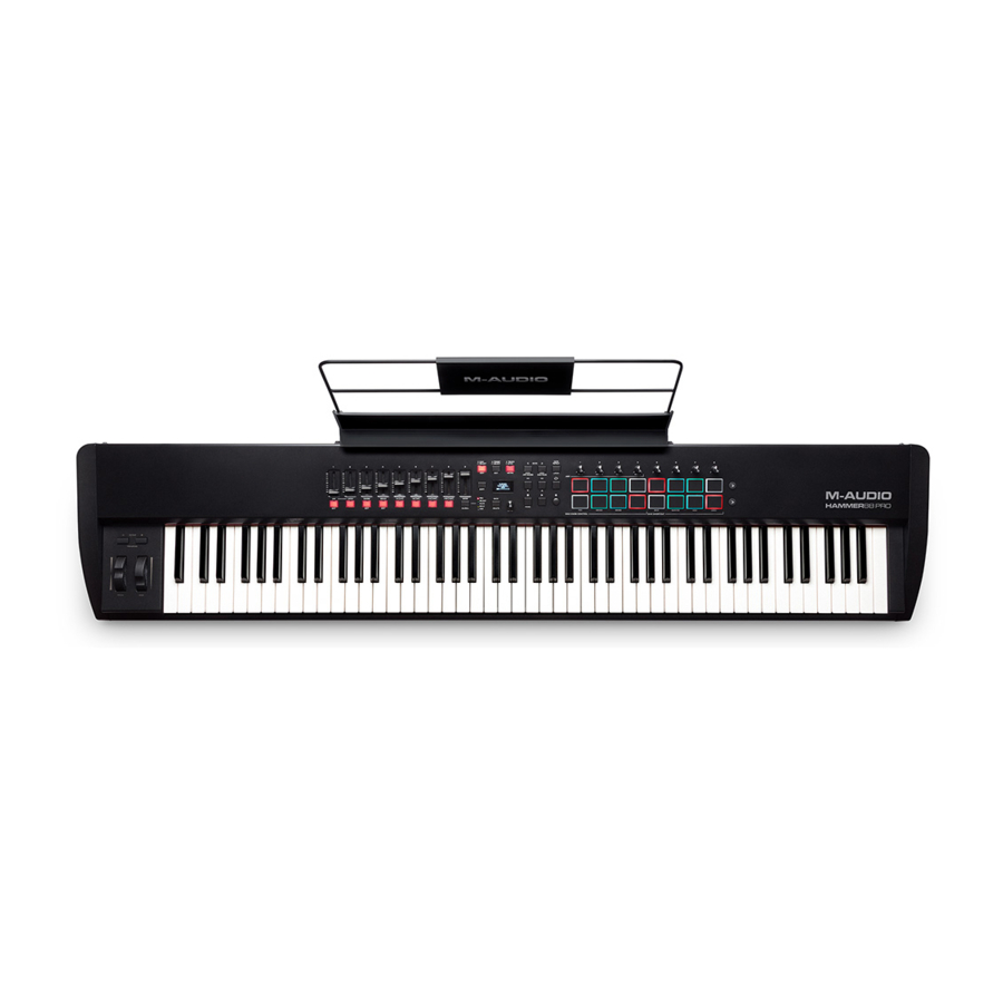
Hammer 88 Pro
This document contains sensitive proprietary information.
All recipients must have a current non-disclosure agreement
on file with M-Audio.
Do not make illegal copies of this document.
The information in this document contains privileged and confidential information. It is
intended only for the use of those authorized by M-Audio. If you are not the authorized,
intended recipient, you are hereby notified that any review, dissemination, distribution
or duplication of this document is strictly prohibited. If you are not authorized, please
contact M-Audio and destroy all copies of this document. You may contact M-Audio at
support@m-audio.com.
© Copyright M-Audio
Confidential
M-Audio
[MK49]
Service Manual
v1.0
2021-01-25
ATTENTION!
M-Audio Service Manual
Advertisement

Related Manuals for M-Audio Hammer 88 Pro


Summary of Contents for M-Audio Hammer 88 Pro
- Page 1 Do not make illegal copies of this document. The information in this document contains privileged and confidential information. It is intended only for the use of those authorized by M-Audio. If you are not the authorized, intended recipient, you are hereby notified that any review, dissemination, distribution or duplication of this document is strictly prohibited.
- Page 2 As the owner of the copyright to the Manual, M-Audio does not give you the right to copy the Manual, and you agree not to copy the Manual without the written authorization of M- Audio.
- Page 3 ALL REPAIRS DONE BY ANY ENTITY OTHER THAN AN AUTHORIZED M-AUDIO SERVICE CENTER SHALL BE SOLELY THE RESPONSIBILITY OF THAT ENTITY, AND M-AUDIO SHALL HAVE NO LIABILITY TO THAT ENTITY OR TO ANY OTHER PARTY FOR ANY REPAIRS BY THAT ENTITY.
-
Page 4: Safety Instructions
The product is exposed to water or excessive moisture, c. The AC power supply plug or cord is damaged, d. The product shows an inappropriate change in performance or does not operate normally, or e. The enclosure of the product has been damaged. Confidential M-Audio Service Manual... - Page 5 MIDI KEYBOARD HAMMER88 PRO SERVICE MANUAL...
- Page 6 Contents Layout & Connection....................3 General Exploded Drawing and List....................4 Circuit Boards..........................5 Parts List............................9 PCB Boards..........................1 7 Diagnosis............................20 Calib ration............................28 Spare Parts List..........................35...
-
Page 32: Cannot Turn On The Power
1. Cannot turn on the power Problem with the 5V USB power: Cannot turn on the instrument when using USB power. Check if the computer is turned on. Check if the USB port on computer is working properly. Check if the USB cable is damaged. Try with another USB cable. Check if the PIN1 on USB jack has 5V voltage. Check if the USB jack is properly soldered. If it is damaged, replace it. Check if the related components of the USB jack are properly soldered. Check both ends of FB2, the grounding should have 5V voltage. If not, then check if FB2 is properly soldered. If the FB2 is damaged, replace it. Check if the toggle switch is damaged. Check if the voltage on both ends of D8 and D9 is normal, if only one end has it, then D8 and D9 have virtual welding or damage, and the damage will be replaced. Problem with the 9V power adapter: Check if PIN1 of DJ1 detects 9V, Check if DJ1, L2, FB12, FB13, D11 and D2 are welded correctly or ... - Page 33 damaged, otherwise need to be replaced and repaired. Under the circumstance that DJ1 has 9V, U2's PIN3 can output 5V. If it still cannot be repaired after welding, U2 has been damaged and needed to be replaced. Use a multimeter to measure whether the voltage of 3.3V and 5V is short with the ground. If short, cut the line and check the location of short circuit. Determine whether U1 can output 3.3V, check whether PIN5 has 3.3V, if not, then replace the chip. Check whether there is 3.3V at both ends of L4 to determine whether there is virtual welding or damage. Determine whether U31 can output 3.3V, check whether PIN2 has 3.3V, if not, then replace the chip. Check whether there is 3.3V at both ends of L12 to determine whether there is virtual welding or damage. ...
- Page 34 Check if A1 chip is working properly: Check whether A1 (U4) chip circuit and SPI FLASH (U11) welding is normal. Test whether there is 12MHz waveform on crystal oscillator resistor R1/R3 to determine whether the crystal oscillator circuit is normal. Check whether the PIN1 of reset chip U6 rises to 3.3V and appears about 40ms later than the power supply when it is powered on. If abnormal, check the relevant circuit. Test whether the associated signal to SPI FLASH is normal. If all the above are normal, A1 and SPI FLASH chips need to be replaced. 2. No response from function buttons Check the cable connection between the keyboard circuit, the function board and the mainboard. Check whether each key button is installed correctly. No response when pressing the keyboard: Check the ribbon cable on the keyboard circuit, the ribbon cable/socket between the keyboard circuit and the mainboard are properly soldered or if it’s damaged. Check the mainboard’s 88‐key socket to A1 keyboard PIN, check if it’s properly soldered or if there’s short‐circuit. No response when pressing the control buttons: Check if the buttons and LED circuit are properly soldered. Check if the key circuit welding is normal, whether there is virtual welding, leakage welding. Make sure that the wiring and sockets connected from the key board to the main board are welded, connected or damaged. ...
- Page 35 Check whether the keys have a scan signal. 3. LED Display Error Check whether the connection line and socket between the small board where the LED is and the main board are normal. Check whether the power supply and grounding of the small board where the LED is located are normal. Check whether the LED circuit is welded normally and whether the device is damaged by false welding. Check the LED for scanning signal. 4. OLED Display Error Check whether the connection line and socket between the OLED panel and the motherboard are normal. ...
- Page 36 OLED connector OLED backlight booster circuit 5. Cannot save the data For the SPI FLASH issues, please refer to the A1 chip part in this section Cannot turn on the power. Check if the SPI FLASH is properly soldered, or if the chip is damaged. 6. MIDI issues Check whether MIDI block and MIDI line are normal. Check if the MIDI Out circuit is properly soldered. If the triode is damaged, replace it. ...
- Page 37 7. Hit PAD issues Check that the PAD structure is installed correctly. Check whether the connection line and socket between the PAD and the motherboard are normal. Check whether the power and ground are normal on the PAD. Check whether r125/165 is welded normally on the PAD. Check PAD strike signal, otherwise the sensor is damaged. Check whether the U27/33 (4051) circuit is welded normally. If PIN3 has no output, replace 4051. 8. Issues related to the pedal, slider, knob Pedal circuit includes CC PEDAL/SUSTAIN. Check if the sockets and related circuit is properly soldered or damaged. Slider issues: Check whether the connection line and socket are connected properly. Check whether the power supply and ground are normal on the small plate where the push rod is located. Check whether the push rod circuit is welded normally and whether the device is damaged by virtual welding. Check whether the U5 (4051) circuit is welded normally and PIN3 cannot output signals, then replace the 4051. ...
- Page 38 Appendix: Circuit board panorama Figure 1: Motherboard front Figure 2: Back of the main board ...
Need help?
Do you have a question about the Hammer 88 Pro and is the answer not in the manual?
Questions and answers