
Related Manuals for ADC WorldDSL UTU-701C


Summary of Contents for ADC WorldDSL UTU-701C
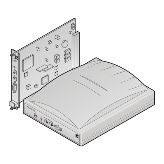
- Page 1 WorldDSL WorldDSL UICK NSTALLATION UIDE UTU-701C List 1 Rate Selectable Line Unit Part Number: 150-1422-01C ETU-751C List 1 Rate Selectable Desktop Unit Part Number: 150-1432-01C l d D G . 7...
- Page 2 In no event shall ADC be liable for any damages resulting from loss of data, loss of use, or loss of profits, and ADC further disclaims any and all liability for indirect, incidental, special, consequential or other similar damages.
- Page 3 Unpack each container and inspect the contents for signs of damage. If the equipment has been damaged in transit, immediately report the extent of damage to the transportation company and to ADC DSL Systems, Inc. Order replacement equipment, if necessary.
- Page 4 Unpack and Inspect Your Shipment 700-701-900-02, Revision 02 June 5, 2002 UTU-701C and ETU-751C List 1...
-
Page 5: Table Of Contents
700-701-900-02, Revision 02 Table of Contents ABLE OF ONTENTS Overview _______________________________________________ 1 Rate Selectable HDSL ............. 1 UTU-701C Line Unit ............... 1 ETU-751C Desktop Unit ............2 Transmission Ranges ............... 2 Compatibility ................3 Shelves and Enclosures for UTU-701C ....3 Connector Adapters for ETU-751C...... - Page 6 Table of Contents 700-701-900-02, Revision 02 Viewing Status __________________________________________18 Main Console Screen..............18 Monitor Screens ..............20 Monitor LTU and NTU Interface Screens ....20 Monitor HDSL Span 1 Screen .........22 Product Support_________________________________________23 Certification and Warranty _________________ Inside Back Cover June 5, 2002 UTU-701C and ETU-751C List 1...
- Page 7 700-701-900-02, Revision 02 List of Figures IST OF IGURES UTU-701C Front Panel ................4 ETU-751C Front Panel................4 ETU-751C Rear Panel................7 Line and Desktop Unit Jumper Settings..........9 UTU/ETU Console Port and Maintenance Terminal Pinouts ....14 IST OF ABLES Transmission Ranges with ETSI Noise..........
- Page 8 List of Tables 700-701-900-02, Revision 02 viii June 5, 2002 UTU-701C and ETU-751C List 1...
-
Page 9: Overview
700-701-900-02, Revision 02 Overview VERVIEW ™ This guide contains installation information for the ADC WorldDSL UTU-701C List 1 and ETU-751C List 1 Rate Selectable HDSL line and desktop units. HDSL ELECTABLE WorldDSL RS (rate selectable) is a single pair High-bit-rate Digital Subscriber Line (HDSL) solution that offers extended reach capabilities through the use of industry-leading multi-rate DSL technology. -
Page 10: Etu-751C Desktop Unit
Overview 700-701-900-02, Revision 02 The UTU-701C accepts the DTE payload at its G.703 port and transports the data to the remote unit at the selected HDSL rate. The UTU-701C requires -36 to -72 Vdc from a local power supply or an enclosure’s AC-to-DC power supply;... -
Page 11: Compatibility
700-701-900-02, Revision 02 Overview OMPATIBILITY The UTU-701C and ETU-751C are compatible with the following ADC WorldDSL products. Shelves and Enclosures for UTU-701C • EMS-830 List 2 Exchange Office Management Shelf, rear connector access (part number 150-1400-11). • EMS-832 List 2 Exchange Office Management Shelf, front connector access (part number 150-1402-11). -
Page 12: Front Panels
Overview 700-701-900-02, Revision 02 RONT ANELS The components on the UTU-701C and ETU-751C front panels are shown below. Their functions are described on page 5 page HDSL LEDs I/F ALM LED Loopback LEDs and push buttons Bar code label (located on circuit side of line card) V.24 (RS-232) console port Warranty control... -
Page 13: Utu And Etu Front Panel Components
700-701-900-02, Revision 02 Overview UTU and ETU Front Panel Components Item Function HDSL SYNC LED Displays synchronization state for the HDSL loop. HDSL ALM LED Displays alarm state for the HDSL loop. I/F ALM LED Displays alarm state for the G.703 data port. LOC LPBK LED Displays local (LOC) loopback state. -
Page 14: Utu And Etu Front Panel Led Indications
For information on loopback testing and loopback LED indications, see the WorldDSL RS user guide, document number 700-701-100-xx. This document can be downloaded from the ADC website at www.adc.com. To order a hard copy, please contact your sales representative. June 5, 2002... -
Page 15: Etu-751C Rear Panel
700-701-900-02, Revision 02 Overview ETU-751C R ANEL The components on the ETU-751C rear panel are shown and described below. Ω Power cord D15F 120 D9F HDSL line receptacle connector G.703 connector Ω Ω BNC 75 BNC 75 On/Off switch G.703 In Connector G.703 out connector ETU-751C Rear Panel ETU-751C Rear Panel Components... -
Page 16: Installation
Before installing the line or desktop unit, inspect it for signs of damage. If the unit has been damaged in transit, immediately report the extent of the damage to the transportation company and to ADC DSL Systems, Inc. AFETY To ensure your safety when servicing and installing this equipment, please... -
Page 17: Line And Desktop Unit Installation
700-701-900-02, Revision 02 Installation INE AND ESKTOP NSTALLATION This section describes the jumper and cable connections required when installing the UTU-701C line unit and the ETU-751C desktop unit. Wear an antistatic wrist band connected to earth ground when installing these units. Avoid unnecessary contact with board-mounted components. -
Page 18: Line Unit Installation
Installation 700-701-900-02, Revision 02 In compliance with the ITU G.703, jumper P8 allows connection of the outer conductor of the coaxial pair, or the screen of the symmetrical pair, to earth (frame ground) at the G.703 input data port. Do one of the following: •... -
Page 19: Desktop Unit Installation
700-701-900-02, Revision 02 Installation Desktop Unit Installation The ETU chassis must be connected to earth ground for protection of the equipment and for personnel safety. Die Geraete Erdung des ETU muss via die Haupt-Erdung (Erdpotential) guarantiert werden, um das Geraet zu schuetzen und die Sicherheits des Personals zu gewaehrleisten. -
Page 20: Hdsl Startup And Synchronization
Installation 700-701-900-02, Revision 02 Connect the HDSL line cable from the DTE to the mating connector on the ETU rear panel. The pinouts for the HDSL line connector are listed at the top of page 12. HDSL Line Connector Pinouts Signal Description HDSL_RING_A... -
Page 21: System Configuration
700-701-900-02, Revision 02 System Configuration YSTEM ONFIGURATION After synchronization is established, the HDSL system can be configured and performance can be monitored from the local unit. If the HDSL link is down, the only parameters that can be changed are those on the local unit. The LTU also provides a special lockout feature that prevents users connected to the NTU console port from changing the circuit configuration. -
Page 22: Logging On
System Configuration 700-701-900-02, Revision 02 UTU/ETU Console Port and Maintenance Terminal Pinouts OGGING To log on to the maintenance terminal Console screen: Press the SPACEBAR several times to activate the autobaud feature and to display the Logon Password screen. ENTER Pressing the key activates the factory default password. -
Page 23: Navigating Menus
700-701-900-02, Revision 02 System Configuration AVIGATING ENUS Use the keys described in the following table to navigate the Console screen and its menus. Console Screen Navigation Keys These Keys Perform this Function Alpha-numeric Type the underlined or highlighted letter to select and execute a menu keys item. -
Page 24: System Settings
System Configuration 700-701-900-02, Revision 02 YSTEM ETTINGS The following table lists the settings available in the Config System Settings menu. The settings in boldface type are factory default settings. Settings in Config System Settings Menu Settings Description Application Mode SINGLE System uses a single pair of twisted copper wires to transport data. -
Page 25: Ltu And Ntu Interface Settings
700-701-900-02, Revision 02 System Configuration NTU I NTERFACE ETTINGS The following table lists the settings available in the Config LTU and Config NTU Interface menus. The settings in boldface type are factory default settings. Settings in Config LTU and Config NTU Interface Menus Settings Description Primary Timing... -
Page 26: Hdsl Payload Rates
Viewing Status 700-701-900-02, Revision 02 HDSL P AYLOAD ATES As illustrated in the following table, time slots 0 and 16 cause the rate selectable G.703 system to increase the selected HDSL payload rate by either 128 kbps (1 through 30 time slots selected) or 64 kbps (31 time slots selected). In structured mode, however, time slots 0 and 16 do not contain data and are transparent to the G.703 input. -
Page 27: Information Displayed In Main Console Screen
700-701-900-02, Revision 02 Viewing Status Information Displayed in Main Console Screen Field Description Circuit Configuration G.703 Indicates the interface standard for G.703 data port. n TS Indicates the number of time slots (n) mapped to the G.703 interface. Timing Indicates the primary source the unit uses for clock synchronization: External 2.048 MHz clock. -
Page 28: Monitor Screens
Viewing Status 700-701-900-02, Revision 02 Information Displayed in Main Console Screen (Cont.) Field Description Loss of Clock Applies to loss of external clock when EXT timing is used. The external (LOC) clock was lost for the previous second. This alarm is reset when the clock is active again. - Page 29 700-701-900-02, Revision 02 Viewing Status Information Displayed in Monitor LTU and NTU Interface Screens Field Description G.703 Port Errored Seconds The number of one-second intervals in which at least one bipolar (ES) 24 Hour violation (BPV) or one CRC-4 error was detected at the G.703 input Count port during the last 24hours.
-
Page 30: Monitor Hdsl Span 1 Screen
Viewing Status 700-701-900-02, Revision 02 Monitor HDSL Span 1 Screen The following table lists the information displayed in each field of the Monitor HDSL Span 1 screen. Information Displayed in Monitor HDSL Span 1 Screen Field Description Current Margin Indicates the excess signal-to-noise ratio relative to a 10 bit error (dB) (MAR) rate. -
Page 31: Product Support
ADC Customer Service Group provides expert pre-sales and post-sales support and training for all its products. Technical support is available 24 hours a day, 7 days a week by contacting the ADC Technical Assistance Center at the number listed below. • Quotation Proposals Sales Assistance •... - Page 32 Product Support 700-701-900-02, Revision 02 June 5, 2002 UTU-701C and ETU-751C List 1...
- Page 33 60-month warranty period per ADC's instructions and which product is confirmed by ADC not to comply with the foregoing warranty. ADC warrants that, for a period of 90 days from the date of purchase, the software furnished with its products will operate substantially in accordance with the ADC published specifications and documentation for such software.
- Page 34 ADC DSL Systems, Inc. 14402 Franklin Avenue Tustin, CA 92780-7013 Tel: 714.832.9922 Fax: 714.832.9924 Technical Assistance ISO 9001/TL 9000 DNV Certification, Inc. REGISTERED FIRM : 700-701-900-02 OCUMENT ´,C4¶20¨ 1235202...
Need help?
Do you have a question about the WorldDSL UTU-701C and is the answer not in the manual?
Questions and answers