cetoni NEMESYS Operating Manual
Hide thumbs
Also See for NEMESYS:
- Hardware manual and reference (57 pages) ,
- Hardware manual and reference (28 pages)
Table of Contents
Advertisement
Quick Links
Advertisement
Table of Contents

Related Manuals for cetoni NEMESYS


Summary of Contents for cetoni NEMESYS
- Page 1 Original Setup and Operating Manual 2.01 – May 2015 neMESYS OEM Hardware Manual...
- Page 2 The information and data contained in this document are subject to change without prior notice. No part of this document may be copied or transmitted without the express consent of cetoni GmbH, irrespective of the means used for this purpose – electronic or mechanical. The general terms of cetoni GmbH apply.
- Page 3 (LAN). Copying or any other duplication of the entire software or parts thereof or mixing and connecting it with other software products is expressly prohibited. For backup purposes the buyer may create a single copy of the software. Cetoni GmbH reserves the right to alter, develop, improve or replace the software.
- Page 4 GmbH Wiesenring 6 D- 07554 Korbussen Germany Tel.: +49 (0) 36602 338-0 Fax: +49 (0) 36602 338-11 E-Mail: info@cetoni.de Internet: www.cetoni.de neMESYS Hardware Manual...
-
Page 5: Table Of Contents
4. Technical Data ................16 4.1. Performance Data ................. 16 4.2. Dimensional Drawing of Pump .............. 18 4.3. Standard Valve ..................19 4.4. Dimensional Drawing of Valve .............. 19 4.5. Dosing Performance ................20 5. Transport and Storage ..............21 neMESYS Manual - Content... - Page 6 7.3. CAN Interface (J3 / J4) ................32 7.3.1. Pin Assignment ..................32 7.3.2. Technical Data ..................32 7.3.3. Connecting neMESYS to CAN bus line CiA DS-102 ........ 32 7.4. RS-232 Connection (J5) ................. 33 7.4.1. Pin Assignment ..................33 7.4.2.
- Page 7 9.4.3. Data Connection through RS232 ............53 9.5. Step 3 – Power Supply of additional Modules ........53 9.6. Step 4 – Data Connection to additional Modules ......... 53 9.7. Step 5 – CAN Bus Termination .............. 53 10. Disposal ..................55 neMESYS Manual - Content...
-
Page 8: Revision History
1.2. Revision History Date Modification 1.03 17.08.2010 Creation of Manual 2.00 09.01.2015 Revision for new Hardware RS232 cable modified (DSub jack instead of plug) 2.01 30.03.2015 Added logic table for valve switching neMESYS Manual - Content... -
Page 9: Introduction
2. Introduction 2.1. Preface Thank you for purchasing a cetoni product. With this manual we would like to support you in using the device. For additional questions or comments please feel free to contact us directly. 2.2. Symbols and Keywords... -
Page 10: Basic Information
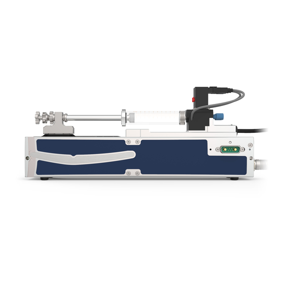
II A has been issued. 3.2. Intended Use 3.2.1. General Description of the Component neMESYS devices are syringe pumps. They enable emptying and filling of syringes through a linear relative movement between a syringe holder and a piston holder. -
Page 11: Proper Use
3.2.2. Proper Use The neMESYS syringe pump system is intended for high-precision and pulsation- free dosing of fluids in a range from nanoliters to milliliters per second. Depending on the device being used, pressures in excess of several hundred bar may be reached. - Page 12 The information provided in the “Technical Data” section with respect to the maximum operating temperature must be observed. cetoni GmbH is not liable for potential impacts caused by the user extending the system with peripheral devices in a way that causes one or both of these values to be exceeded.
-
Page 13: Measures For Safe Setup
3.2.6. Safe Operation Measures 3.2.6.1 Electromagnetic Emissions The neMESYS syringe pump system is designed for usage in any facility directly connected to a public supply network that also supplies buildings used for residential purposes. -
Page 14: Condition Of Devices
The devices left our facilities in perfect condition and may only be opened by cetoni GmbH. If a device is opened by an unauthorized person, all warranty and liability claims shall be void, in particular those referring to personal injury. - Page 15 GmbH or an authorized party, and if the devices are used in accordance with the user manual. The neMESYS syringe pump system complies with the applicable safety rules and standards. cetoni GmbH reserves all property rights for the relevant wiring, processes, names, software and devices.
-
Page 16: Technical Data
1 Mbit / s (standard 1 Mbit / s) RS232 RxD; TxD max. 115200 bit / s (115200 bit / s) Mechanical Data Weight approx. 1100 g Dimensions (L x W x H) 310 x 47 x 130 mm Attachments M3 screws neMESYS Manual – Technical Data... - Page 17 3-pole plug JST XARR-03V plug connector: 3-pole socket JST XAP-03V-1 on device: 4-pole plug JST XARR-04V RS232 plug connector: 4-pole socket JST XAP-04V-1 Signal on device: 12-pole plug JST XARR-12V plug connector: 12-pole socket JST XAP-12V-1 neMESYS Manual – Technical Data...
-
Page 18: Dimensional Drawing Of Pump
4.2. Dimensional Drawing of Pump neMESYS Manual – Technical Data... -
Page 19: Standard Valve
There is a danger of damaging the housing or sealing material. Before using the valve for the first time, please check the chemical compatibility of the media you want to use with the PEEK housing material and the FFKM (perfluoroelastomer) sealing material. neMESYS Manual – Technical Data... -
Page 20: Dosing Performance
Min. pulsation-free speed [µm/s] 14.648 1.042 0.502 Max. speed [mm/s] 6.33 3.06 1 ml syringe Min. flow [µl/min] 0.065 0.065 0.065 with 60 mm Min. pulsation-free flow [µl/min] 14.648 1.042 0.502 stroke Max. flow [ml/min] 6.33 3.05 neMESYS Manual – Technical Data... -
Page 21: Transport And Storage
When used properly the device is maintenance-free. Should you encounter problems that you cannot fix yourself or which require opening the device, please contact cetoni GmbH to discuss further actions. The device may only be opened by cetoni GmbH or authorized service staff. Violating this rule will void the warranty. -
Page 22: Hardware Operation
6. Hardware Operation 6.1. Installing a Syringe The syringe holder on neMESYS modules allows the use of syringes with outside diameters of 6 to 30 mm and a maximum piston stroke of 65 mm. IMPORTANT Use high-quality glass syringes with outside diameters of 6 to 30 mm to guarantee precise flow rates. - Page 23 The syringe position can be varied somewhat by shifting the piston holder. To do that, loosen the screw with a 4mm Allen wrench. neMESYS Manual – Hardware Operation...
- Page 24 Put the clamping piece back on and insert the adapter plate matching the piston diameter in such way that the piston head sits between the piston holder and the adapter plate. neMESYS Manual – Hardware Operation...
-
Page 25: Fluidic / Valve
6.2. Fluidic / Valve The neMESYS module can be fitted with an optional valve. This valve allows you to switch the syringe connector between your application (outlet) and a reservoir (intake), thereby enabling automatic refilling of the syringe. - Page 26 A FFKM membrane (shaded green area) connected to the rocker seals off the fluidic flow. The membrane also limits the valve’s operating pressure to 3 bar. CAUTION Please observe the maximum operating pressure of 3 bar to avoid damage to the standard valve. neMESYS Manual – Hardware Operation...
-
Page 27: Removing Valves
Please observe the correct placement of the valve plug. The white area should face the valve, while the rocker should point away from the valve. Rocker You can then simply lift the valve to remove it. neMESYS Manual – Hardware Operation... - Page 28 Manual – Hardware Operation...
-
Page 29: Electrical Interfaces
(figure 1). The following interfaces are available: Figure 1 – Electrical Interfaces Connector Interface J1 / J2 Power supply 24VDC In / Out J3 / J4 CAN interfaces In / Out RS232 interface I/O signal interface neMESYS Manual – Electrical Interfaces... -
Page 30: Power Supply (J1 / J2)
Typical current draw of one module: 0.3 A Surge current draw of one module: 0.6 A Information regarding contacts Plug Molex mini-Fit Jr.TM 2-pole type (39-01-2020) connectors Crimp contacts Molex mini-Fit Jr.TM crimp socket (444-76-1111) Crimp tool Molex crimp tool (69008-0724) neMESYS Manual – Electrical Interfaces... - Page 31 Manual – Electrical Interfaces...
-
Page 32: Can Interface (J3 / J4)
Maximum bit rate 1 Mbit/s Protocol CANopen DS-301, DS-402 Node ID Software 7.3.3. Connecting neMESYS to CAN bus line CiA DS-102 neMAXYS CAN 9 Pin D-Sub (DIN41652) Pin 1 “CAN_H” Pin 7 “CAN_H” high bus line Pin 2 “CAN_L” Pin 2 “CAN_L” low bus line Pin 3 “CAN_GND”... -
Page 33: Rs-232 Connection (J5)
RS232 shield 7.4.2. Technical Data Maximum input voltage ± 30 V Output voltage typically ± 9 V @ 3k grounded Maximum bit rate 115200 bit/s (standard 38 400 bit/s) Internal RS232 driver/receiver EIA RS232 Standard neMESYS Manual – Electrical Interfaces... -
Page 34: Connecting Nemesys To A Pc
7.4.3. Connecting neMESYS to a PC neMESYS RS-232 (JST) PC RS-232 (DSUB) Pin 1 “neMESYS TxD” Pin 2 “PC RxD” Pin 2 “neMESYS RxD” Pin 3 “PC TxD” Pin 3 “GND” Pin 5 “GND” IMPORTANT Please observe the maximum Baud rate of the RS232 interface on your PC or micro controller. -
Page 35: Signal Connection (J6)
DigOUT 2 Digital output 2 “multi-purpose” / valve switching DigOUT 5 Digital output 5 “multi-purpose” Digital signal ground +24 VDC Auxiliary voltage 24 VDC +5 VDC Auxiliary voltage output 5 VDC AGND Analog signal ground neMESYS Manual – Electrical Interfaces... -
Page 36: Analog Input 1 And 2 (Pin 1 And 2)
Figure 4 – Analog input 1 and 2 7.5.3. Digital Inputs 1 and 2 (Pin 3 and 4) “Multi-purpose” inputs can be freely configured and utilized by the user. DigIN1 Pin [3] DigIN2 Pin [4] Pin [9] Type of input Single ended neMESYS Manual – Electrical Interfaces... - Page 37 < 0.8 VDC Level 1 typically > 2.0 VDC Input resistance typically 8 k Input current at level 1 typically 270 µA @ 5 VDC Switching delay < 300µs Figure 5 – Digital input 1 and 2 neMESYS Manual – Electrical Interfaces...
-
Page 38: Digital Input 7 (Pin 5)
-7.5 … + 12.5 VDC Level 0 typically < 0.8 VDC Level 1 typically > 2.0 VDC Input resistance typically 20 k against GND Max. input frequency 2.5 MHz Figure 6 – Digital input 7 “single-ended” neMESYS Manual – Electrical Interfaces... -
Page 39: Digital Output 1 And 2 (Pin 6 And 7)
Switching delay <3 µs Figure 7 – Digital output 1 and 2 7.5.5.2 Wiring Examples DigOUT “Drain” Maximum input voltage +36 VDC Maximum load current 50 mA Maximum voltage drop <1.0 V @ 50 mA neMESYS Manual – Electrical Interfaces... - Page 40 Figure 8 – Digital output 1 and 2 wiring example “drain” DigOUT “Source” 5V – 0.75V – (I x 2200 ) Output voltage load 2 mA Maximum load current load Figure 9 – Digital output 1 wiring example “source” neMESYS Manual – Electrical Interfaces...
-
Page 41: Digital Output 5
<10 ns Figure 10 – Digital output 5 7.5.6.2 Wiring Examples DigOUT “Drain” 3.3 VDC Maximum input voltage 24 mA Maximum load current x 100 ) Maximum voltage drop <0.55 V + (I drop neMESYS Manual – Electrical Interfaces... - Page 42 Figure 11 – Digital output 5 “drain” DigOUT “source” 3.3V – 0.75V – (I x 100 ) Output voltage load 24 mA Maximal load current load Figure 12 – Digital output 5 wiring examples “source” neMESYS Manual – Electrical Interfaces...
-
Page 43: Can-Bus Termination
1 to 0 after approximately 1 second. This causes the voltage of the coil current to decrease (15 V) and thereby lessens the heating effect. To switch the valve to the other direction simply set both outputs to 0. neMESYS Manual – Electrical Interfaces... - Page 44 Activating the coil in the valve for an extended period of time causes the coil to heat up, which, in case of low flow rates, may warm up the medium flowing through the valve. Lowering the valve voltage after switching lessens this heating-up effect. neMESYS Manual – Electrical Interfaces...
-
Page 45: Cable Set
2 x 1.5 mm Side A Cable end sleeves 1.5 mm Side B Molex Mini-Fit Jr. 39-01-2020 Molex Mini-Fit Jr. crimp contact socket 444-76-xxxx 8.2. Power Connection cable Pins A Signal Pins B Ground – Power GND neMESYS Manual – Cable Set... -
Page 46: Can Cable (Terminated Dsub Socket)
3 x 0.125 mm , twisted pair, shielded Side A D-Sub socket DIN 41652, 9-pole type, with attachment screws, 120 resistor between CAN high (7) and CAN low (2) Side B 3-pole socket JST XAP-03V-1 neMESYS Manual – Cable Set... -
Page 47: Can Cable (Dsub Plug)
CAN high Technical Data Cable size 3 x 0.125 mm , twisted pair, shielded Side A D-Sub plug DIN 41652, 9-pole type, with attachment screws Side B 3-pole socket JST XAP-03V-1 8.5. CAN Connection Cable neMESYS Manual – Cable Set... -
Page 48: Can Terminator
3-pole socket JST XAP-03V-1 8.6. CAN Terminator Pins A Signal Pins B CAN high CAN low CAN GND Technical Data Termination 120 resistor between CAN high (1) and CAN low (2) Plug connector 3-pole socket JST XAP-03V-1 neMESYS Manual – Cable Set... -
Page 49: Rs232 Cable (Dsub Socket)
TxD neMESYS RxD Technical Data Cable size 3 x 0.125 mm , twisted pair, shielded Side A D-Sub plug DIN 41652, 9-pole type, with attachment screws Side B 4-pole socket JST XAP-04V-1 8.8. USB-to-CAN Adapter neMESYS Manual – Cable Set... - Page 50 CAN shield CAN GND CAN low CAN high Technical Data Cable Size 3 x 0.125 mm , twisted pair, shielded Side A D-Sub plug DIN 41652, 9-pole type, with attachment screws Side B USB type A neMESYS Manual – Cable Set...
-
Page 51: Setup & Cable Connection
Use M3 bolts for attachment. 9.2. Introduction to Cable Connection Two different cable connections are required for installing neMESYS pumps: 1. Connection of the first module to the power supply and the controller (PLC, PC) 2. -
Page 52: Step 2 - Data Connection
USB-to-CAN adapter. Option 2 – If you want to integrate the neMESYS pumps into an existing CAN bus, please use the CAN cable (DSub plug). Connect the cable to CAN interface of the first neMESYS OEM module. -
Page 53: Data Connection Through Rs232
OEM CAN termination plug. If a neMESYS OEM module is the first device in your CAN network, insert the CAN terminator into CAN connector J3. If you use the CAN cable (terminated DSub socket), this will not be necessary since the resistor is already integrated into the neMESYS Manual –... - Page 54 DSub socket. If a neMESYS OEM module is the last module in your CAN network, insert the CAN terminator into CAN connector of this module. neMESYS Manual – Cable Connection...
-
Page 55: Disposal
10. Disposal Please send your old devices back to cetoni GmbH. We will take care of proper disposal pursuant to the relevant laws and regulations. Before you send a device back to cetoni, please decontaminate it, if required, and add a completed contamination declaration to your shipment.
Need help?
Do you have a question about the NEMESYS and is the answer not in the manual?
Questions and answers