Table of Contents
Advertisement
Quick Links
Advertisement
Table of Contents

Related Manuals for LAVAZZA blue LB 1200 USA CLASSY PRO 120V


Summary of Contents for LAVAZZA blue LB 1200 USA CLASSY PRO 120V
- Page 1 LB 1200 USA CLASSY PRO 120V TECHNICAL SUPPORT MAINTENANCE MANUAL...
- Page 2 LB 1200 USA CLASSY PRO 120V Machine code 18000248 Rel. 0.00 Edition 02/2020 © Copyright LAVAZZA S.p.A. To request technical support, contact: TECHNICAL SERVICE LAVAZZA sending an e-mail to: technicalservice@lavazza.com phoning n°: +39 011 2398429, or consulting the website: https://ts.lavazza.com...
-
Page 3: Table Of Contents
Technical support maintenance manual CONTENTS 1. GENERAL INFORMATION OF MANUAL ... 1 7.2.1.5. Power off ............10 1.1. STRUCTURE OF MANUAL ......1 7.2.2. TECHNICAL MENU ........10 1.1.1. Scope and contents ........1 7.2.2.1. Recipes ............11 1.1.2. Messages used ........... 1 7.2.2.2. - Page 4 Technical support maintenance manual CONTENTS 12.10. EXTRACTING THE WATER TANK INLET VALVE ............36 12.11. REMOVING THE CAPSULE DRAWER SENSOR ........... 37 12.12. REMOVING THE INTERFACE BOARD . 37 12.13. REMOVING THE POWER CABLE CONNECTOR ........... 38 12.14. EXTRACTING THE DISPENSING UNIT . 38 12.14.1.
-
Page 5: General Information Of Manual
This manual is intended for technicians qualified to per- the contents of this manual. If in doubt as to how to cor- form maintenance on the machine. Lavazza will not be rectly interpret the instructions, contact Lavazza S.p.A. for clarifications thereof. -
Page 6: General Safety Standards
Structural damage, improper modifications, tampering, machine. Lavazza will not be held liable for damage alterations or repairs can endanger the safety of the caused by failure to comply with the general safety machine. -
Page 7: Handling And Storage
Technical support maintenance manual - Do not use water jets for washing any part of the ap- 4. DEMOLITION AND WASTE DISPOSAL pliance because running water can seriously damage 4.1. INSTRUCTIONS FOR END-OF-LIFE electrical and electronic components. DISPOSAL TREATMENT - During hot water and steam dispensing, do not direct This product conforms to Directive 2012/19/EU and the the jets toward others or yourself. -
Page 8: Overview Of The Machine
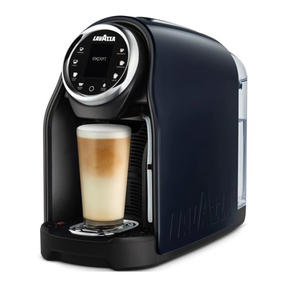
Technical support maintenance manual 5. OVERVIEW OF THE MACHINE 5.1.3. TECHNICAL FEATURES Power supply voltage 120 V 5.1. MODEL Power supply frequency 60 Hz LB 1200 USA CLASSY PRO 120V Installed power 1450 W Water tank capacity 60.8 US fl. oz. (1.8 L) Boiler type THERMOBLOCK Through the... -
Page 9: External Components
Technical support maintenance manual 5.2.1. EXTERNAL COMPONENTS 5.2.2. INTERNAL COMPONENTS 1) Tank cover 1) Dispensing unit 2) Water tank 2) 3-way solenoid valve 3) Power cable 3) Ceramic valve 4) Capsule loading lever 4) Y-valve 5) User interface 5) Electronic board 6) Milk tube 6) Thermoblock 7) Dispensing spout... -
Page 10: User Interface
Technical support maintenance manual 6. INSTALLATION, COMMISSIONING AND CONFIGURATION 6.1. UNPACKING Open the package taking care not to damage it. Extract the machine, pulling it out of the protective casing. Environment The components making up the packaging must be separated based on the nature of the materials and disposed of in compliance with laws in force regarding separate waste collection and disposal. -
Page 11: Start-Up Procedures
Adjust the dose as follows: guide; - insert a capsule Lavazza BLUE or EXPERT in the rel- - remove the water tank, rinse and fill it using only fresh evant compartment;... -
Page 12: Machine Menus And Available Functions
Technical support maintenance manual - release the button; For the implementation of the procedures to follow, the - dispensing begins; indications are shown on the display. [Programming allows to adjust the dose of each of the USER MENU TECHNICAL MENU parts that compose the beverage, i.e. -
Page 13: Recipes
Technical support maintenance manual 7.2.1.1. RECIPES Warning The FROTHER RINSING must be carried out after Viewing and editing of data relating to the delivery of each preparation of a milk based beverage. the drinks. - Insert one end of the milk tube into the hole on the drip Espresso temp. -
Page 14: Technical Menu
Technical support maintenance manual 7.2.2. TECHNICAL MENU Auto switch off (Stand-by) To access, select “Technical Menu” inside the user Setting the inactivity times that passes before the unit menu and confirm with the MULTIFUNCTION button. automatically goes into Standby. The unit requires inputing a password (default is 1111). 10 minutes Below are the functions, sub-menu and available pa- 20 minutes... -
Page 15: Recipes
Technical support maintenance manual 7.2.2.1. RECIPES Functions Sub-menu Parameters Partial Viewing and editing of data relating to the delivery of Reset partial the drinks. Total Statistics Display partial Espresso temp. Display total Back Parameter allows you to adjust three temp. levels for the espresso: Exit BTLE activation... - Page 16 Technical support maintenance manual B) Brew unit rinsing Note C) Clean milk spout D) System filling By factory default, this unit value is set to “0 - 160 ppm (0 - 9° dH)”. E) Blocking milk F) Blocking timeout Descaling A) FROTHER RINSING The “Descaling”...
-
Page 17: Settings
Technical support maintenance manual Note RESET ALL RECIPES If the frother is not rinsed, the milk drink buttons remain switched off and cannot be selected. F) BLOCKING TIMEOUT Reset successful Defines the maximum time (min 5 hours and max 30 Please press key hours) in which it is possible to dispense drinks before the FROTHER RINSING is required. -
Page 18: Statistics
Technical support maintenance manual ECO mode Total Setting the inactivity time that passes before the unit Reading the total statistics of the products dispensed. automatically goes into Eco mode. TOTAL STATISTICS 5 minutes PRODUCTS 10 minutes Espresso: Lungo: 15 minutes Coffee 8 oz.: 20 minutes Macchiato:... -
Page 19: Service
Technical support maintenance manual INPUTS 1 BLUETOOTH INFORMATION MAC address: Flow Water Firmware: Tray Lever CLOSE Connected: Please press key Press the MULTIFUNCTION button to return to the sub- The “Flow” sensor indicates the pulses of the volumet- menu. ric metering device. The “Water”... - Page 20 Technical support maintenance manual • Screen 5/9 CER. VALVE Test operation of the pump. K1 Init. K4 Pos up K5 Pos down PUMP K1 Pump K4/5 0 INIT Flow 0 ml/min I-Zero I-Switch - Pressing button ESPRESSO “T1” sets valve milk in Position “0 INITIAL”.
- Page 21 Technical support maintenance manual • Screen 6/9 • Screen 9/9 Screen 6 displays the status of the 3-way solenoid Screen 9 displays the end of the test. valve. EXIT VALVE K1 Valve EXIT WITH POWER KEY Press the MULTIFUNCTION button to return to the By pressing the button ESPRESSO “T1”...
- Page 22 Technical support maintenance manual Each button is associated with a small square that cor- Note responds to its position on the display. Use the scroll arrows ▲ ▼ to pass from one screen- By pressing a button, the corresponding LED turns off and a green dot fills the corresponding square.
-
Page 23: Credit
Technical support maintenance manual • Screen 14/14 B) DISPLAY PHONE Screen 14 displays the end of the test. Enable or disable the display of the technical assistance number during the error reports. Exit 14/14 C) RESET EXIT WITH POWER KEY Elimination of the technical assistance phone number. -
Page 24: User Menu
Technical support maintenance manual Statistics Display alarm Parameter “Statistics” shows the number of residual Enabling the viewing of credit statistics when powering credits and the alarm threshold. on the unit. CREDIT STATISTICS CREDIT STATISTICS Rest credit: Rest credit: Alarm at: Alarm at: Please press key Please press key... -
Page 25: Routine Maintenance
“CLEAN MILK SPOUT” function in the unit menu the LAVAZZA descaling product and water, as indi- - unless there are specific indications, clean the exter- cated on the package of the descaling product;... - Page 26 Technical support maintenance manual Warning When the machine is used intensively, perform the cleaning operations more frequently. Note Do not leave water in the circuit and tank for more than 3 days. If this should occur, empty, rinse and refill the tank with fresh water. Then run a dispens- ing cycle (with no capsule) before dispensing bev- erages.
-
Page 27: Recommended Tools For Disassembly And Assembly Operations
Technical support maintenance manual 9. RECOMMENDED TOOLS FOR DISASSEMBLY AND ASSEMBLY OPERATIONS T6 Torx Screwdriver T10 Torx Screwdriver T20 Torx Screwdriver Flat-headed screwdriver 0.5x3 Long nose pliers Standard pliers Rel. 0.00 / February 2020... -
Page 28: General Operations
Technical support maintenance manual 10. GENERAL OPERATIONS Attention The machine has electric components and components which generate high temperatures. Disconnect the machine from the electrical mains and wait for the hot parts to cool off before performing disassembly and assembly operations. During disassembly and assembly operations, wear clothing and/or personal protec- tive equipment intended by current legislation regarding safety at work. -
Page 29: Removal Of Hydraulic Connections
Technical support maintenance manual Figure C: disconnect this type of wiring by separating the male con- nector from the female by pulling it outwards. 10.2. REMOVAL OF HYDRAULIC CONNECTIONS This paragraph describes all the types of disconnection of the hydraulic pipes on the machine. Figure A: remove the type of hy- draulic pipe shown in the figure by pulling the pipe outwards to dis-... - Page 30 Technical support maintenance manual Note Recover the gaskets (3) and in- sert them in the pipes as shown in figure C. Replace the gaskets if worn. Rel. 0.00 / February 2020...
-
Page 31: Disassembling The Body
Technical support maintenance manual 11. DISASSEMBLING THE BODY 11.1. PULLING OUT THE MILK TUBE Figure A: pull down on the tube and pull it from the unit 11.2. EXTRACTING THE DRIP TRAY / USED CAPSULE DRAWER AND WATER TANK Figure A: after having removed the power cable from the socket, remove the DRIP TRAY / USED CAPSULE TRAY. -
Page 32: Removing The Top Cover
Technical support maintenance manual Figure B: extract the side panels by applying upward force. 11.4. REMOVING THE TOP COVER Figure A: use a flathead screw- driver to lift and release the clips on the top cover (three per side and one at the front). Figure B: open the capsule load- ing lever and extract the top cover. -
Page 33: Removing The Machine Base
Technical support maintenance manual 11.5. REMOVING THE MACHINE BASE Figure A: unscrew the six screws indicated. Extract the base. 12. REMOVING INTERNAL COMPONENTS The internal parts can be accessed after having removed the body parts. 12.1. DISASSEMBLING THE PUMP Warning Wait for the boiler to cool off before performing these operations. -
Page 34: Dismantling The Steam Discharge Unit
Technical support maintenance manual Figure C: pull the PUMP slightly out of its housing to remove the bottom water connection. Then extract the component. 12.2. DISMANTLING THE STEAM DISCHARGE UNIT Figure A: remove the water con- nection and the two screws indi- cated. -
Page 35: Dismantling The Water Level Capacitive Sensor
Technical support maintenance manual Figure B: remove the four water connections, after pull outing the clips present. Warning Pay attention to the position of the tubes during reassembly. Figure C: lift the indicated tab and pull out the ceramic valve (1). 12.4. -
Page 36: Removing The 3-Way Solenoid Valve
Technical support maintenance manual 12.5. REMOVING THE 3-WAY SOLENOID VALVE Figure A: unscrew the screws indicated and disconnect the two water lines. Figure B: remove the solenoid valve from the unit and separate it from the support (1), pressing the lever (2) outward. -
Page 37: Dismantling The Thermoblock
Technical support maintenance manual Note When replacing the solenoid valve unit assy, the pair of O- RINGS within each connection point must be replaced with the TEFLON PIPES, as shown in figure D. 12.6. DISMANTLING THE THERMOBLOCK Warning Wait for the boiler to cool off before performing these operations. DANGER OF BURNS. Figure A: remove the two water connections indicated and the wiring highlighted by the CPU... -
Page 38: Y-Valve Dismantling
Technical support maintenance manual Figure C: remove the two screws and remove the heater. 12.7. Y-VALVE DISMANTLING Figure A: disconnect the water connections and unscrew the screw. Pull out the Y-valve (1). 12.8. REMOVING THE FLOWMETER Figure A: in the base of the ma- chine, press down on the indicat- ed interlocking lever and slightly extract the volumetric meter (1). -
Page 39: Extracting The Mechanical Filter
Technical support maintenance manual Warning The water connection to the tank drain valve must be re- moved from the water tank inlet valve (2), as shown in Figure B. The second connection with the mechanical filter (3) can instead be removed from the flowmeter. 12.9. -
Page 40: Extracting The Water Tank Inlet Valve
Technical support maintenance manual 12.10. EXTRACTING THE WATER TANK INLET VALVE Figure A: disconnect the water hose connected to the flowmeter and unscrew the two indicated screws. Warning The water connection to the flowmeter must be removed from the water tank inlet valve, as shown in Figure B. -
Page 41: Removing The Capsule Drawer Sensor
Technical support maintenance manual 12.11. REMOVING THE CAPSULE DRAWER SENSOR Figure A: disconnect the indicat- ed electrical wiring from the CPU BOARD. Figure B: unscrew the screw in the machine base and extract the sensor (1). 12.12. REMOVING THE INTERFACE BOARD Figure A: in the machine base, remove the electrical connection and the indicated screw. -
Page 42: Removing The Power Cable Connector
Technical support maintenance manual 12.13. REMOVING THE POWER CABLE CONNECTOR Figure A: disconnect the two elec- trical connections indicated by the CPU board and the grounding ca- ble (heater side). Figure B: lift the indicated tabs (two on one side of the unit, one on the other) and pull out the con- nector (1). -
Page 43: Disassembling The Dispensing Unit
Technical support maintenance manual Figure B: disconnect the indi- cated water connection, removing the fastening FORK. 16.44 Figure C: unscrew the four fas- tening screws of the Unit (two per side. Lift the capsule loading lever and extract the Dispensing unit. 12.14.1. - Page 44 Technical support maintenance manual Figure B: Extract the micro (2) and actuator (3). Figure C: unscrew the two high- lighted screws and extract the dis- pensing spout (4). Figure D: unscrew the indicated screw and remove the ejector (5). Rel. 0.00 / February 2020...
- Page 45 Technical support maintenance manual Attention During re-assembly, do not force the ejector back into its housing, but rather insert it in the indicated hole, following its particular shape. Figure F: with the capsule loading lever half-lowered, pull the slide (6) outward and lift it. Extract the capsule frame (7).
- Page 46 Technical support maintenance manual Figure H: with the capsule load- ing lever raised, extract the slide base (8) outward, making a slight clockwise movement. Repeat the steps described in Figures G - H for the right-hand slide. Figure I: in the Unit base, extract the indicated clip and pull out the dispensing hose fitting (9).
- Page 47 Technical support maintenance manual Figure M: remove the capsule loading lever. Note To replace the lever, the three screws in the base must be un- screwed. Figure N: at the same time as the extraction of the lever spacers, also remove the piercer assembly (11).
-
Page 48: Extracting The User Interface
Technical support maintenance manual Figure P: extract the indicated gasket and check its wear. If it needs to be replaced, make sure it is lubricated before being inserted in its housing. Figure Q: extract the coffee outlet gasket (13) to clean or replace it if necessary. - Page 49 Technical support maintenance manual Figure B: unscrew the two indi- cated screws in the machine base. Figure C: hold the display and push it upward to release the side fastening teeth (1). Figure D: pry with a screwdriver at the point indicated (one per side) to pull out the user interface assembly.
- Page 50 Technical support maintenance manual Figure E: remove the LED sup- port (2). Figure F: in the lower part of the user interface, pull the two indi- cated side tabs and pull the milk module (3) downward to extract it. Figure G: remove the two screws indicated and remove the coffee outlet support (4).
-
Page 51: Extracting The Cpu Board
Technical support maintenance manual Figure I: unscrew the four screws of the display, disconnect the two marked connectors and separate the display from the user interface. 12.16. EXTRACTING THE CPU BOARD Figure A: disconnect all the wires present, unscrew the indicated screw and push upward on the BOARD to extract it. -
Page 52: Diagrams
Technical support maintenance manual 13. DIAGRAMS 13.1. WIRING DIAGRAM BTLE Modul Machine components Thermoblock Water level capacitive sensor Thermoblock thermal fuse Capsule drawer sensor Thermoblock temperature probe Capsule loading lever micro Power cable connector Micro ceramic valve (step) Pump Micro ceramic valve (zero) Pump thermal protector CPU board 3-way solenoid valve... -
Page 53: Hydraulic Diagram
Technical support maintenance manual 13.2. HYDRAULIC DIAGRAM Milk Machine components Tank NANO flowmeter Mechanical filter Pump Thermoblock Y-valve 3-way solenoid valve Ceramic valve Steam discharge unit Milk module Drip tray Dispensing unit Rel. 0.00 / February 2020...
Need help?
Do you have a question about the blue LB 1200 USA CLASSY PRO 120V and is the answer not in the manual?
Questions and answers