Table of Contents
Advertisement
Available languages
Available languages
Quick Links
Advertisement
Table of Contents

Related Manuals for Dresser RR 16


Summary of Contents for Dresser RR 16
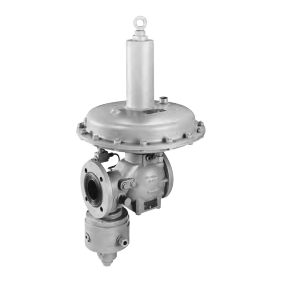
- Page 1 Gas Regulators Gasdruckregler RR 16 Gas Pressure Regulator RR 16 Régulateur de pression RR 16 Регулятор давления газа RR 16 111-099-2801 Betriebsanleitung Instruction Manual Mode d’emploi Руководство по эксплуатации...
-
Page 3: Table Of Contents
Inhaltsverzeichnis / Contents / Contenu / Содержание Seite Page Страница DE Schematische Darstellung Regelgerät / Materialangaben . . . . . . . . . . . . . . . . . . . . . . . . . . . . . . . . . . . . 4 Beschreibung / Technische Daten / Typ-Auswahl . -
Page 4: Schematische Darstellung Regelgerät / Materialangaben
RR 16 Schematische Darstellung / Schematic section / Représentation schématique / Схематическое представление Justierschraube “ Adjusting screw Atmungsanschluss Vis de tarage Breather line connection Юстировочный винт Raccordement évent Присоединение дыхательной линии “- EO 12 Membrane Messleitungsanschluss Diaphragm Sensing line connection Мембрана... -
Page 5: Beschreibung / Technische Daten / Typ-Auswahl
Beschreibung Der RR 16 ist ein direkt wirkender, federbelasteter Gasdruckregler . Durch unterschiedliche Stellantriebe und Düsengrößen kann der Regler für alle Aufgaben der Gasversorgung im Kommunal-, Gewerbe- und Indus- triebereich jeweils optimal an die geforderten Durchflussleistungen angepasst werden . Technische Daten • Eingangsdruck pu:... -
Page 6: Führungsbereiche Regler Und Sav
130 - 230 mbar 65 – 115 mbar 955-203-77 orange 210 - 480 mbar 100 – 240 mbar 955-203-76 schwarz Regelgerät RR 16 Ü (Überström-Regelgerät) Stellantriebgehäuse / DN / wds Feder-Nr Farbe Draht-Ø (mm) DN 25 DN 50, 80 10 – 20 mbar 955-202-70 20 –... - Page 7 + pdsu 1,0 – 1,7 bar 955-201-68 schwarz Grenzwerte SAV SL-IZ…; 033; 022 und SID* Bei den Gas-Druckregelgeräten RR 16 bestimmt allein die Membrangehäusegröße des Regler-Stellantriebes den höchsten Abschaltdruck pdso des SAV’s: Stellantriebsgehäuse-Ø Max . höchster Einstelldruck pdo des SAV’s 12“-Membrangehäuse 0,3 bar über pds...
-
Page 8: Sicherheitshinweise Und Eu Konformitätserklärung
• Bei Korrosionsgefahr im Innen- und Außenbereich muss das Gerät regelmäßig untersucht werden und bei merklicher Korrosion aus dem Verkehr genommen werden . • Das innere Volumen des Druckraumes des RR 16 beträgt: . Geräte-Typ V = . . L... - Page 9 • Abhängig vom Aufstellungsort des Gerätes sind gegebenenfalls Schallschutzmaßnahmen zu treffen . Hinweise für den Ex-Einsatz (ATEX): • Wenn in der unmittelbaren Reglerumgebung Flugrost möglich ist, sind alle Aluminium-Außenteile ent- sprechend zu schützen (z . B . durch Lackieren) . •...
-
Page 10: Einbauanleitung Regler Und Sav / Wartung Und Reparatur
Installation Atmungsleitung • Der maximale Eingangsdruck in der Anlage darf • Atmungsanschluss G “ nicht höher sein als der max . zulässige Eingangs- • Der Atmungsanschluss am Regelgerät ist zur Si- druck des Reglers . cherstellung für schnelle Lastwechsel an folgende • ... -
Page 11: Dämpfungsmaßnahmen / Strömungsscheibe
Wartung und Reparaturen Alle Arbeiten am Regelgerät sind nur im drucklosen Zustand durchzuführen . Die Sicherheitsvorschriften, insbesondere die UVV’s, sowie die DVGW-Arbeitsblät- Stellantrieb H ter G 491 und G 495 sind zu beachten: “-Außen-Vierkant • Absperrventil auf der Ein- und Ausgangsseite ist zu schließen • ... - Page 12 Strömungsscheibe für Durchflussmengen < 10 % von qmax (< 1:10) DN 25 DN 50 DN 80 Konstruktionsstand bis April 1998 Konstruktionsstand bis April 1998 TM Ventilteller 111-360-20 111-163-10 Düsen ø 24 111-163-10 Düsen ø 24 Düsen ø 54 Konstruktiosstand ab Mai 1998 (Bankett an der Unterseite) 111-363-15 für Düsen ø...
-
Page 13: Einbau Schalldämmeinrichtung / Sav-Stellungsanzeiger
Schalldämmeinrichtung Schalldämm- Montagehilfe: einrichtung 3-mal M4x10 DIN 912 Zur Montage/Demontage Innensechskanntschrauben M 4 x 10 einschrauben und Schalldämmeinrichtung mittels Werkzeug Nr . 74-111-381 . 0 1 herausschrau- ben (nur DN 50), DN 25 und DN 80 direkt mit 6-kt-Steckschlüssel SW 22 . SAV-Stellungsanzeiger Initiator Rückstellwelle... -
Page 14: Beschreibung Selbstschließendes Druckausgleichsventil
Selbstschließendes Druckausgleichsventil, Technische Daten: Typ BV Nennweite: DN 5, m . Anschl . G “ • zum Anbau an Gasdruckregelgeräte mit integriertem max . Betriebsdruck: SAV: = 16 bar Das Druckausgleichsventil BV besteht aus einem rechteckigen Aluminium-Profil, mit einem in Längs- Temperaturbereich: richtung eingebauten, druckausgeglichenem Kolben . -
Page 15: Inbetriebnahme Sav 033, Sl-Iz
Sicherheitsabsperrventil 033 Inbetriebnahme Anschlag Messleitungsanschluss Die Reihenfolge der Inbetriebnahme des SAV-033 hat wie nachfolgend beschrieben, zu er- folgen! Bei Nichteinhaltung der Reihenfolge wird der Ventiltellerarm an der noch in Auslöseposition stehenden Verriegelung des Auslösehebels (3) vorbei geführt und die Verriegelungskante des Ventiltellerarmes kann verbogen werden! a) ... - Page 16 Sicherheitsabsperrventil SL-IZ… Inbetriebnahme Abblase-/ Atmungsanschluss “B” Messleitungs- anschluss „A” Die Reihenfolge der Inbetriebnahme des SAV-SL-IZ hat wie nachfolgend beschrieben, zu er- folgen! Bei Nichteinhaltung der Reihenfolge wird der Ventiltellerarm an der noch in Auslöseposition stehenden Verriegelung des Auslösehebels (3) vorbei geführt und die Verriegelungskante des Ventilteller- armes kann verbogen werden! a) ...
- Page 17 Sicherheitsabsperrventil 022 Inbetriebnahme Anschlag Messleitungsanschluss Die Reihenfolge der Inbetriebnahme des SAV-022 hat wie nachfolgend beschrieben, zu er- folgen! Bei Nichteinhaltung der Reihenfolge wird der Ventiltellerarm an der noch in Auslöseposition stehenden Verriegelung des Auslösehebels (3) vorbei geführt und die Verriegelungskante des Ventiltellerarmes kann verbogen werden! a) ...
- Page 18 Sicherheitsabsperrventil SID- Inbetriebnahme Atmungsanschluss 6 . 1 Messleitungsanschluss NOT AUS Die Reihenfolge der Inbetriebnahme des SAV-SID hat wie nachfolgend beschrieben, zu er- folgen! Bei Nichteinhaltung der Reihenfolge wird der im Reglerventilkörper befindliche Ventilteller- arm an der noch in Auslöseposition stehenden Verriegelung des Auslösehebels (3) vorbeigeführt und die Verriegelungskante des Ventiltellerarmes kann verbogen werden! a) Druckausgleich durch Öffnen des selbsttätig schließenden Druckausgleichventils, bis sich Schließdruck einstellt .
-
Page 19: Description / Technical Data / Type-Selection
Description The RR 16 is a direct-acting, spring loaded gas pressure regulator . With different actuators and orifices, the regulator is used for gas supply networks, industries, heating plants and for all installations with continuous consumption or rapid variations of flow-rate . -
Page 20: Spring Range Regulator And Ssv
130 - 230 mbar 65 – 115 mbar 955-203-77 orange 210 - 480 mbar 100 – 240 mbar 955-203-76 black Regulator RR 16 Ü (Relief regulator) Actuator / DN / wds Spring-No . : Colour Wire-Ø (mm) DN 25 DN 50, 80 10 –... - Page 21 Limiting values of set points for SSV SL-IZ…; 033; 022 and SID* With RR 16 gas pressure regulators, only the diaphragm size of the regulator actuating drive deter-mines the highest shut-off pressure pdo of the SSV . Actuating Drive Body-Ø...
-
Page 22: Safety Instructions And Eu Declaration Of Conformity
V in litres 10,6 13,6 • The inner chamber volume of the RR 16 regulator amounts to:: • The cleaning of the devices has to be done without using any alcohol containing solvent or cleaning agents . • The device is not appropriate for floods and loads by earthquakes . - Page 23 Remarks for use in potentially explosive atmospheres (ATEX): • If film of rust is possible (flying rust in the immediate product surroundings), all outer aluminium parts have to be protected accordingly (e . g . by varnish) . • The product must be electrically connected to adequately earthed installation . •...
- Page 24 Installation Breathing line • Check that the maximum inlet pressure is not • Breathing connection G “ higher than the design pressure of the regulator . • To realize fast load changes of the regulator, the fol- • Regulator should be lifted only with belts around lowing cross sections of breathing line are to ob- the body .
-
Page 25: Instruction Of Installation Regulator And Ssv / Service And Repair
Service and repair • All work on the regulator is to carry out only in the pressure-free condition . The safety reg- ulations, in particular the UVV‘s, as well as the Actuator unit H DVGW papers G 491 and G 495 are to be con- “-Square head sidered: • ... - Page 26 Flow Disc for flow volumes < 10 % of qmax (< 1:10) DN 25 DN 50 DN 80 Design framework till April 1998 Design framework till April 1998 Valve disk assy . 111-360-20 orifice 111-163-10 orifice ø 24 111-163-10 orifice ø 24 ø...
-
Page 27: Installation Silencer / Ssv-Position Indicator
Assembly (optional) of silencer, respectively SSV position indicator: Silencer Assembly aid: 3 M 4 x 10 DIN 912 For assembly/disassembly, screw in Allen screws M 4 x 10 and screw out sound insulation with tool no . 74-11-381 . 0 1 (DN 50 only), DN 25 und DN 80 directly with SW 22 hex spanner . -
Page 28: Description Of Manipulation-Valve (Selfe Closing)
Self-Closing Manipulation Valve, Type BV Technical Data: Nominal width: DN 5, with G ” connection • for mounting on gas pressure regulators with inte- Max . operating pressure: grated SSV: pmax = 16 bar The BV manipulation valve consists of a rectangular Temperature range: aluminium profile with a pressure-compensated pis- - 20°C to + 60 °C... -
Page 29: Start-Up Instruction Of Ssv 033, Sl-Iz
Safety shut-off valve 033 Start-up instructions Stopper Control line connection The sequence of start-up the SSV 033 is to be observed! If the sequence is not considered, the valve disc arm contacts the inside of valve body and the chamfered edge of valve disc arm (3) can be deformed . a) ... - Page 30 Safety shut-off valve SL-IZ.. Start-up instructions Exhaust-/ Breathing-Connection ãB“ Control line Connection ãA“ The sequence of start-up the SSV SL-IZ . . is to be observed! If the sequence is not considered, the valve disc arm contacts the inside of valve body and the chamfered edge of valve disc arm (3) can be deformed .
- Page 31 Safety shut-off valve 022 Start-up instructions Stopper Control line connection Messleitungsanschluss The sequence of start-up the SSV 022 is to be observed! If the sequence is not considered, the valve disc arm contacts the inside of valve body and the chamfered edge of valve disc arm (3) can be deformed .
- Page 32 Safety shut-off valve SID- Start-up instructions Breathing Connection 6 . 1 Control line connection EMERGENCY SHUTOFF The sequence of start-up the SSV-SID is to be observed! If the sequence is not considered, the valve disc arm contacts the inside of valve body and the chamfered edge of valve disc arm (3) can be deformed .
-
Page 33: Description / Caractéristiques Techniques / Choix Du Type
Description Le RR 16 est un régulateur de pression directement actif et commandé par ressort . Les différents action- neurs et tailles de buse permettent une adaptation optimale du régulateur aux débits exigés pour toutes les tâches de l’alimentation en gaz au niveau communal, commercial et industriel . -
Page 34: Gammes De Pression Régulateur Et Vanne De Sécurité
65 – 115 mbar 955-203-77 orange 210 – 480 mbar 100 – 240 mbar 955-203-76 noir Régulateur RR 16 Ü (régulateur de trop-plein) Ø filet métallique Actionneur / DN / wds Ref . du ressort Couleur (mm) DN 25 DN 50, 80 10 –... - Page 35 Limites SAV SL-IZ… ; 033 ; 022 et SID* Dans le cas des régulateurs de pression RR 16, c’est uniquement la taille du boîtier de la membrane de l’actionneur qui détermine la pression de coupure la plus élevée pdso de la vanne SAV : Ø...
-
Page 36: Conseils De Sécurité Et Certificat De Conformité Ue
10,6 13,6 • Le volume interne du compartiment de pression du RR 16 est égal à : . • Pour le nettoyage de l’appareil, ne jamais utiliser des produits contenant de l'alcool ou des solvants . • L'appareil n'est pas conçu pour une utilisation dans le cas d'inondations et pour résister à des tremblements... - Page 37 • Avant de démonter l'appareil, s'assurer qu'il n'y ait plus de pression à l'intérieur de l'appareil . Du gaz rési- duel peut se présenter lors du démontage . S'assurer de la présence d'un dispositif de ventilation suffisam- ment puissant . •...
-
Page 38: Instructions De Montage Régulateur Et Vanne De Sécurité / Entretien Et Réparation
Installation Conduit d’aération • La pression d’entrée maximale présente dans le sys- • Raccordement évent G “ tème ne devra jamais excéder la pression d’entrée • Pour assurer une réponse correcte aux variations maximale admissible du régulateur . rapides de charge, le raccordement de l'évent sur •... -
Page 39: Mesures D'amortissement / Rondelle D'écoulement
Entretien et réparations Toute intervention sur l’équipement de régulation doit se faire hors pression . Les normes nationales de sécu- rité en vigueur dans le pays, en particulier le règlement Actionneur H de prévention des accidents, doivent être impérative- carré mâle “... - Page 40 Rondelle d’écoulement pour quantités < 10 % de qmax (< 1:10) DN 25 DN 50 DN 80 Version construct . jusqu’à avril 1998 Version construct . jusqu’à avril 1998 Clapet de régul . TM 111-360-20 111-163-10 buses ø 24 111-163-10 buses ø 24 Buses ø...
-
Page 41: Montage Équipement D'insonorisation / Indicateur De Position Vanne De Sécurité
Dispositif d’insonorisation Dispositif Aide de montage : d’insonorisation 3 fois M4x10 DIN 912 Pour le montage/démontage, visser les vis à six pans creux M 4 x 10 et dévisser le dispositif d’insonorisation moyennant l’outil No . 74-111-381 . 0 1 (uniquement DN 50), DN 25 et DN 80 directement avec clé... -
Page 42: Description Soupape Compensatrice De Pression À Fermeture Automatique
Soupape de compensation de pression à Caractéristiques techniques : fermeture automatique type BV Diamètre nominal : DN 5, raccord G “ • pour montage sur des régulateurs de pression avec Pression de service max . : vanne de sécurité intégrée : = 16 bar La soupape de compensation de pression BV est com- Plage de température :... -
Page 43: Mise En Service Sav 033, Sl-Iz
Vanne de sécurité SAV 033 Mise en service Butée Prise d’impulsion Respecter l’ordre de la mise en service de la SAV-033, comme décrit ci-après ! Dans le cas d’un non-respect de l’ordre, le bras du clapet est guidé à côté du verrouillage du levier de déclenchement (3) toujours en position de déclenchement et le bord de verrouillage du bras du clapet risque d’être tordu ! a) Equilibrage de la pression en ouvrant la soupape compensatrice de pression à... - Page 44 Vanne de sécurité SL-IZ… Mise en service Raccordement évent/ décharge « B » Prise d’impulsion « A » Respecter l’ordre de la mise en service de la SAV SL-IZ, comme décrit ci-après ! Dans le cas d’un non-respect de l’ordre, le bras du clapet est guidé à côté du verrouillage du levier de déclenchement (3) toujours en position de déclenchement et le bord de verrouillage du bras du clapet risque d’être tordu ! a) Equilibrage de la pression en ouvrant la soupape compensatrice de pression à...
- Page 45 Vanne de sécurité SAV 022 Mise en service Butée Prise d’impulsion Messleitungsanschluss Respecter l’ordre de la mise en service de la SAV-022, comme décrit ci-après ! Dans le cas d’un non-respect de l’ordre, le bras du clapet est guidé à côté du verrouillage du levier de déclenchement (3) toujours en position de déclenchement et le bord de verrouillage du bras du clapet risque d’être tordu ! a) Equilibrage de la pression en ouvrant la soupape compensatrice de pression à...
- Page 46 Vanne de sécurité SID Mise en service Raccordement évent 6 . 1 Prise d’impulsion ARRET D’URGENCE Respecter l’ordre de la mise en service de la SAV SID, comme décrit ci-après ! Dans le cas d’un non-respect de l’ordre, le bras du clapet qui se trouve dans le corps de la vanne de régulation est guidé...
-
Page 47: Описание / Технические Характеристики / Выбор Типа
Описание Устройство RR 16 - это регулятор давления газа прямого действия с пружинной нагрузкой . Благодаря различным исполнительным приводам и размерам сопла можно оптимально со- гласовать регулятор с требуемыми расходными характеристиками для всех задач газоснаб- жения в коммунальных, промысловых и промышленных областях . -
Page 48: Диапазоны Выходного Давления Регулятора И Пко
65 – 115 мбар 955-203-77 оранжевый 210 - 480 мбар 100 – 240 мбар 955-203-76 черный Устройство регулирования RR 16 Ü (перепускное УРДГ) Ø проволоки, Корпус исполн . привода / Ду / wds № пружины Цвет мм Ду 25 Ду 50, 80 10 –... - Page 49 1,0 – 1,7 бар 955-201-68 черный Предельные значения ПКО типов SL-IZ…; 033; 022 и SID* В устройствах регулирования давления газа RR 16 исключительно размер корпуса мембраны исполнительного привода регулятора определяет самое высокое давление pdso срабатывания (отключения) ПКО: Ø корпуса исполнительного привода...
-
Page 50: Указания По Технике Безопасности
10,6 13,6 V = . • Внутренний объем V камеры под давлением RR 16 составляет: • Для очистки устройства средства, содержащие растворители или спирт, использовать нель- зя . • Устройство не предназначено ни для землетрясения, ни для наводнения . - Page 51 • Перед демонтажем устройства полностью сбросить давление . Возможен выход остаточного количества газа, поэтому обеспечьте достаточную аэрацию . • В зависимости от места установки устройства, принятие мер по шумозащите может быть необходимым . Указания по применению во взрывоопасной зоне (ATEX): •...
-
Page 52: Обслуживание И Ремонт
Инсталляция • Для обеспечения быстрых смен нагрузки присоединение дыхания на УРДГ следу- • Максимальное давление на входе уста- ет подключать к следующим поперечным новки должно быть не выше макс . допу- сечениям линий: стимого давления на входе регулятора . Ду 20 до 3 м дыхательной линии •... -
Page 53: Меры Для Демпфирования / Спрямляющий Диск
рекомендации объединения DVGW "G 491" и "G 495", должны соблюдаться: • Закрыть клапан-отсекатель на входной и выходной сторонах . Исполнительный • С помощью воздухоспускного клапана привод Н на выходной стороне регулятора дав- "-овый наружный ления довести давление до нулевого квадрат уровня... - Page 54 Спрямляющий диск для расходов < 10% от qмакс (< 1:10) Ду 25 Ду 50 Ду 80 Конструктивное исполнение до Конструктивное исполнение до Тарельчатый затвор клапана ТМ апреля 1998 г . апреля 1998 г . 111-360-20 111-163-10 сопла ø 24 111-163-10 Сопла ø 24 сопла...
-
Page 55: Монтаж Шумопоглощающего Устройства / Индикатор Положения Пко
Шумопоглощающее устройство Шумопоглощающее устройство Сборочное приспо- собление: 3 штуки M4x10 DIN 912 Для монтажа/демонтажа ввинтить винты М 4x10 с внутренним шести- гранником и вывинтить шумопоглощающее устройство посредством инструмента № 74-111-381 .01 (только Ду 50), Ду 25 и Ду 80 непосред- ственно... - Page 56 Клапан выравнивания давления Технические характеристики: автоматического перекрытия типа Условный проход Ду 5, с присоед . G “ макс . рабочее давление: • для пристройки к устройствам регулиро- = 16 бар макс . вания давления газа со встроенным ПКО: температурный диапазон: Клапан...
-
Page 57: Пуско-Наладка Пко Типов 033, Sl-Iz
Предохранительный клапан-отсекатель типа 033 Пуско-наладка Упор Присоед . измерительной линии Обязательно соблюдайте очередность пуско-наладки ПКО типа 033, которая описы- вается в нижеследующем! В случае несоблюдения очередности плечо клапана перемещается мимо находящейся еще в положении срабатывания фиксации коромысла (3) сраба- тывания, и кромка фиксации плеча может искривляться! а) Выравнивание... - Page 58 Предохранительный клапан-отсекатель типа SL-IZ… Пуско-наладка Сбросное / дыха- тельное присо- единение “B” Присоеди- нение изме- рительной линии „A” Обязательно соблюдайте очередность пуско-наладки ПКО типа SL-IZ, которая описы- вается в нижеследующем! В случае несоблюдения очередности плечо клапана перемещается мимо находящейся еще в положении срабатывания фиксации коромысла (3) сраба- тывания, и...
- Page 59 Предохранительный клапан-отсекатель типа 022 Пуско-наладка Упор Присоед . измери- Messleitungsanschluss тельной линии Обязательно соблюдайте очередность пуско-наладки ПКО типа 022, которая описы- вается в нижеследующем! В случае несоблюдения очередности плечо клапана перемещается мимо находящейся еще в положении срабатывания фиксации коромысла (3) сраба- тывания, и...
- Page 60 Предохранительный клапан-отсекатель типа SID Пуско-наладка Присоединение дыхательной линии 6 . 1 Присоединение изме- АВАР СТОП рительной линии Обязательно соблюдайте очередность пуско-наладки ПКО типа SID, которая описыва- ется в нижеследующем! В случае несоблюдения очередности плечо клапана, находящееся в корпу- се регулирующего клапана, перемещается мимо находящейся еще в положе- нии...
-
Page 61: Abmessungen / Gewichte / Installationsbeispiel
Abmessungen / Dimension / Dimensions / Габаритные размеры G1/2 G1/ 4 G1/ 4 kurzer Federdom G1/ 4 short spring housing cage de ressort courte G1/ 4 короткий купол пружины ПКО т . SAV/SSV SID SAV/SSV SAV/SSV SL-IZ ПКО т . SAV/SSV Nennweite Stellantrieb-... - Page 62 ø ø ø ø ø ø ø ø Gewichte, Befestigungsgewinde / Weight, Screws and threads Gewichte in kg RR 16 mit SAV Anschlussverbindung / Schraubenart Anzahl der SAV 022 *6 kt- *6 kt-Schraube Gewindelöcher Schraube 12 N SID siehe 2) Gewinde DIN 931-5 .
- Page 63 Installationsbeispiel Model installation Die Abbildung zeigt ein Einbaubeispiel des Gas- The diagram shows a model installation of the RR 16 druckregelgerätes RR 16 mit integriertem SAV Typ gas pressure regulator with integrated SSV Type SL- SL-IZ . Die normale Einbaulage ist wie im Bild dar- IZ .
- Page 64 F: +49 (0)721 / 5981 - 282 www.dresserutility.com © 2022 Natural Gas Solutions North America, LLC – All rights reserved. Dresser Utility Solutions reserves the right to make changes in specifications and features shown herein, or discontinue the product described at any time without notice or obligation. Contact your Dresser Utility Solutions representative for the most current information.
Need help?
Do you have a question about the RR 16 and is the answer not in the manual?
Questions and answers