Table of Contents
Advertisement
Quick Links
Surepowr Series
Sure 150
Installation Manual
Table of Contents
Intended of Usage ................................................................... 2
Actuator Range of Application ........................................... 2
1. Actuator Marking .....................................................3
(ATEX)/Conditions of Certification (IECEx) ............3
3. Ratings ......................................................................3
4. Safety ........................................................................4
Safety First! ........................................................................................... 4
Warnings and Notices ...................................................................... 4
Joint Handling .................................................................................... 4
Fasteners ............................................................................................... 5
Seals ........................................................................................................ 5
Cable Glands ....................................................................................... 5
Grounding and Bonding ................................................................ 5
Spring Housing................................................................................... 5
Enclosure Surface Temperature ................................................... 5
5. Installation................................................................6
Dimensional Information ............................................................... 6
Dimensional Information ............................................................... 7
Cover Removal and Assembly ...................................................... 8
Mounting .............................................................................................. 8
Horizontal Mounting .............................................................. 8
Conduit Locations and Thread Sizes .......................................... 9
Cable Glands ....................................................................................... 9
Grounding and Bonding ................................................................ 9
Wiring ..................................................................................................... 9
Wiring Diagrams ....................................................................... 9
Mechanical Stop Settings ............................................................11
Limit Switch Settings .....................................................................11
Limit Switch Settings (Optional Offering) .............................12
Installation.................................................................................12
6. Operation............................................................... 13
Thermal Overload ...........................................................................13
Duty Cycle ..........................................................................................13
Optional Manual Override ...........................................................13
7. Maintenance .......................................................... 13
Mounting Fasteners .......................................................................13
Enclosure Cover Screws ................................................................13
Seals and Cable Glands .................................................................14
8. Storage ................................................................... 14
RCS Actuators
Advertisement
Table of Contents

Summary of Contents for Dresser Surepowr Sure 150
-
Page 1: Table Of Contents
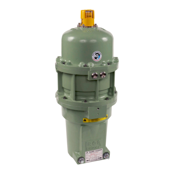
RCS Actuators Surepowr Series Sure 150 Installation Manual Table of Contents Intended of Usage ..............2 Actuator Range of Application ........... 2 1. Actuator Marking .............3 2. Special Conditions for Safe Use (ATEX)/Conditions of Certification (IECEx) ....3 3. Ratings ..............3 4. -
Page 2: Intended Of Usage
Be sure to include the model and serial number located Dresser Natural Gas Solutions (NGS) cannot be held on the nameplate of your Sure 150 actuator in all responsible if these standards are disregarded. -
Page 3: Actuator Marking
A4-80 and yield strength 600 MPa. If marking Enclosure “Tb” fasteners are replaced, they shall be replaced with the equivalent size and grade. Name and Dresser NGS Dresser NGS Some external parts of the equipment are non- Address of 16240 Port 16240 Port... -
Page 4: Safety
4. Safety WARNING Safety First! EXPLOSION HAZARD In the maintenance and operation of mechanical Death or serious injury could result. equipment, safety must be considered at all times. Do not open unless power to Through the use of the proper clothes, tools, and actuator has been disconnected. -
Page 5: Fasteners
Cable Glands Do not open actuator cover if there is risk of an explosive environment. Care must be taken with the Cable glands must be installed and maintained joint surface when handling, installing or storing to and properly torqued according to the Installation preserve the integrity of the explosion-proof joint. -
Page 6: Installation
5. Installation WARNING Notice: HIGH ENERGY HAZARD – SurePowr actuators can be supplied for clockwise or LOADED SPRING counter-clockwise spring-driven rotation (viewed from the top of the actuator). Death or serious injury The spring drive rotation is noted on the could result. -
Page 7: Dimensional Information
Dimensional Information Figure 2... -
Page 8: Cover Removal And Assembly
Cover Removal and Assembly Mounting Do not open the actuator cover if there is risk of an The actuator is shipped in the fail safe position. Ensure explosive environment. that the driven device is oriented to its desired fail position prior to installation or any maintenance work of the actuator. -
Page 9: Conduit Locations And Thread Sizes
Conduit Locations and Thread Sizes Wiring The actuator is supplied with two 2 3/4-inch NPT conduit Connect field wiring per the appropriate wiring diagram entries. Refer to Figure 1 (Sure 150 outline drawing) for supplied with the actuator. conduit entry locations. NOTICE: Use a minimum of #18 AWG stranded wire. -
Page 11: Mechanical Stop Settings
Mechanical Stop Settings NOTICE: Only the fail end of travel stop may be adjusted. The total adjustment available is +/- 5°. Switch 4 Switch 4 Cam 4 Cam 4 (auxiliary switch) (auxiliary switch) To adjust the fail end position, perform the following: Switch 3 Switch 3 (auxiliary switch) -
Page 12: Limit Switch Settings (Optional Offering)
To set the counter-clockwise NOTE: (spring fail position) switch: Ensure the driven device is properly positioned Ensure the actuator is positioned in the counter- in its full fail position. If it is not, use the adjustable end clockwise (fail) position. Ensure the end of travel of travel stop on the Sure 100 (see Figure 4) to properly adjust the fail end of travel stop. -
Page 13: Operation
6. Operation 7. Maintenance Power On: The electric motor drives the gear train, WARNING which in turn winds the spring and turns the device. HIGH ENERGY HAZARD – An internal limit switch de-energizes the motor and LOADED SPRING energizes the brake, which holds the return spring Death or serious injury and device in position. -
Page 14: Seals And Cable Glands
8. Storage correct specified torque. Failure to maintain specified screw torque may compromise the enclosure protection The Surepowr actuator must be stored in a clean, dry, rating. temperature-controlled building that is protected from the weather. Precautions should be taken to prevent The explosion-proof joint may be lubricated with an condensation inside or outside the actuator. - Page 16 Contact your Dresser Natural Gas Solutions representative for the most current information. The Dresser Logo and all Trademarks containing the term “Dresser” are the property of Dresser, LLC, a subsidiary of Baker Hughes, a GE Company. www.dresserngs.com RCS Sure 150 IOM Manual NGS.IPG.0042...


Need help?
Do you have a question about the Surepowr Sure 150 and is the answer not in the manual?
Questions and answers