
Related Manuals for Belanger SpinLite


Summary of Contents for Belanger SpinLite
- Page 1 SpinLite® Full Side Washer SpinLite® Full Side Washer 1MANUAL961 Rev01 Belanger, Inc. * P.O. Box 5470 * Northville, MI 48167-5470 Customer Service Phone (248) 349-7010 * Fax (248) 380-9681...
- Page 3 Do not make additional copies of this manual or electronically transmit it in any form whatsoever, ® in whole or in part, without the prior written permission of Belanger, Inc. The registered trademarks used in this document are the property of their respective owners. The use of such trademarks is for ®...
- Page 5 Changed Motor/Gearbox from 1GEABX-AS660 to 112271 and 1GEABX-AS661 to 112272 (per 85 & 86 Project #10037) Back Cover Updated back cover to new design Belanger, Inc. * PO BOX 5470 * Northville, MI 48167-5470 * Ph (248) 349-7010 * Fax (248) 380-9681 1MANUL961...
-
Page 9: Table Of Contents
Pneumatic Connections: Initial Air Settings for Air Panel ......................51 Electrical Connections: Main Power to Motors and LED Lights ....................52 Electrical Connections: Motor............................... 53 Belanger, Inc. * PO BOX 5470 * Northville, MI 48167-5470 * Ph (248) 349-7010 * Fax (248) 380-9681 1MANUL961... - Page 10 Filler Strips for Passenger Side Arm & Leg Assembly ......................... 96 Air Panel: 102060 Assembled View ............................. 97 Air Panel: 102060 Exploded View ..............................97 Belanger, Inc. * PO BOX 5470 * Northville, MI 48167-5470 * Ph (248) 349-7010 * Fax (248) 380-9681 1MANUL961...
-
Page 11: Belanger Incorporated Limited Warranty
PURPOSE CONTAINED IN THE UNIFORM COMMERCIAL CODE – SALES ARE EXPRESSLY DISCLAIMED. Copyright ©2020 by Belanger, Inc. All rights reserved. No part of this work may be reproduced or transmitted in any form or by any means, electronic or mechanical, including photocopying and recording, or by any information storage or retrieval system, except as may be expressly permitted by the 1976 Copyright Act. -
Page 12: Operational Warning
Chlorinated Solvents Belanger, Inc.®, does not endorse or condone the use of chemicals that are potentially dangerous to human health, the environment, or property. Belanger® recognizes that it is the right and sole decision of the end-user operators of our equipment as to the type and dilution ratio of the chemicals used in their facilities. -
Page 13: Important Safety Information
If you do not understand the procedure, call a Belanger, Inc. representative at 248-349- 7010. It is imperative to your safety and the safety of others to understand the procedures before beginning work. Belanger, Inc. * PO BOX 5470 * Northville, MI 48167-5470 * Ph (248) 349-7010 * Fax (248) 380-9681 1MANUL961... -
Page 14: Important Safety Information - Must Read
THAT MAY BE A TRIP HAZARD. It is imperative to your safety and the safety of others to always follow safe work procedures. Belanger, Inc. * PO BOX 5470 * Northville, MI 48167-5470 * Ph (248) 349-7010 * Fax (248) 380-9681 1MANUL961... -
Page 15: Introduction
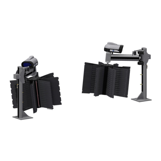
SpinLite® Full Side Washer Introduction Thank you for your purchase of the Belanger, Inc. SpinLite® Full Side Washers. This manual will familiarize you with the SpinLite® Full Side Washer installation, operation, and maintenance. Both the driver and passenger side SpinLite® Full Side Washers are easily assembled and mounted to the tunnel floor. -
Page 16: Before You Get Started
SpinLite® Full Side Washer Introduction Before You Get Started Below is a list of the SpinLite® Full Side Washer equipment you will receive in your shipment and the tools that are needed to install the equipment. Tools needed for installation:... -
Page 17: Specifications
A compressed Air System should be set correctly to support 90 PSI necessary to operate equipment, but should never be set to deliver more than 120 PSI air pressure to the Belanger specified equipment. Belanger, Inc. * PO BOX 5470 * Northville, MI 48167-5470 * Ph (248) 349-7010 * Fax (248) 380-9681 1MANUL961... -
Page 18: General Dimensions
SpinLite® Full Side Washer Specifications General Dimensions Equipment Envelope 107” Top View 187” Entrance View Floor 47-1/2” 13” Conveyor: 102-1/2” 49” 14-1/2” Conveyor: Belanger, Inc. * PO BOX 5470 * Northville, MI 48167-5470 * Ph (248) 349-7010 * Fax (248) 380-9681 1MANUL961... -
Page 19: Inspection
Receiving party is responsible for filing claim with trucking company. Notify your local distributor or Belanger, Inc. immediately if shipment is determined damaged or incomplete. The SpinLite® FSW assemblies each have a 1HP 3-Phase motor that comes wired for the voltage selected when ordered which was either 208/230, 460, or 575 VAC. - Page 20 3) The other end of the LED Cable has a quick connector and will be connected to the Slip Ring Wire inside the Motor/Gearbox Cover during the Installation of the SpinLite® FSW Assemblies. Belanger, Inc. * PO BOX 5470 * Northville, MI 48167-5470 * Ph (248) 349-7010 * Fax (248) 380-9681 1MANUL961...
-
Page 21: Installation
Installation Identify Conveyor The SpinLite® Full Side Washer assemblies can be installed in a tunnel with a Belanger® 13” or 14-1/2” wide Conveyor that has either a single or double guide rail. Identifying the conveyor is crucial for properly positioning the Full Side Washer assemblies during installation. The Belanger® conveyor options are shown in the images below. -
Page 22: Tunnel Placement: Overview
Installation Tunnel Placement: Overview When placing the SpinLite® Full Side Washer assemblies, tunnel depth will vary from site to site. Be sure to allow an adequate operating envelope. There are two traditional installation configurations for the SpinLite® Full Side Washer assemblies. -
Page 23: Staggered, With Quickfire® Plus Assemblies
Note: The above image is shown with cleaning material installed to indicate the operating envelope required for proper function. Belanger, Inc. * PO BOX 5470 * Northville, MI 48167-5470 * Ph (248) 349-7010 * Fax (248) 380-9681 1MANUL961... -
Page 24: Tunnel Placement: Preparation
2) Assuming that there is already a conveyor in place, select the desired location for the equipment. Tunnel Placement: Stand-Alone Installation 1) Take the driver side SpinLite® Full Side Washer Leg Assembly, shown in the image below, and position it into the tunnel first. - Page 25 SpinLite® FSW Leg 5/8” Lag Bolts (6) 7) Next, position the passenger side SpinLite® FSW Leg Assembly in the tunnel so that it is aligned with the driver side unit. 8) Place the passenger side Leg Assembly so that the outside edge of its Baseplate is 102-1/2” from the inside edge of the inside conveyor guide rail, as shown below.
-
Page 26: Tunnel Placement: Staggered Installation With Quickfire® Plus
1) Assuming that the QuickFire® Plus Assemblies have already been installed per the QuickFire® Plus Manual 1MANUL830. 2) Refer to the image below, place the driver side SpinLite® FSW Leg Assembly so that the front edge of its baseplate is 150” from the front edge of the driver side QuickFire® Plus baseplate. - Page 27 Installation Tunnel Placement: Staggered Installation with QuickFire® Plus 4) Once the driver side and passenger side SpinLite® FSW Leg assemblies are in place verify that they are square to the conveyor. 5) Check to make sure they are level by placing a torpedo level on the Baseplate.
-
Page 28: Attach The Arm Assemblies
Installation Attach the Arm Assemblies Locate the SpinLite FSW Arm assemblies and determine which is the driver side and passenger side Arm. The Cylinder Mounts are to face toward the inside of the tunnel. Use the image below for clarification. - Page 29 Arm Pivot Washer Fasteners (1 each per FSW Assembly) (2 each per FSW Assembly) 5/16-18 x 3/4” HHCS 5/16” Lock Washer Belanger, Inc. * PO BOX 5470 * Northville, MI 48167-5470 * Ph (248) 349-7010 * Fax (248) 380-9681 1MANUL961...
- Page 30 10) Replace the previously removed Bearing Covers. It will be necessary to swing the Arm Assembly to one side to re-install the Bearing Covers. Belanger, Inc. * PO BOX 5470 * Northville, MI 48167-5470 * Ph (248) 349-7010 * Fax (248) 380-9681 1MANUL961...
- Page 31 Assembly with the fasteners that shipped in place. Refer to the images below. Step 12: Secure the Cylinder and Shock to the appropriate clevises on the Leg Assembly. Belanger, Inc. * PO BOX 5470 * Northville, MI 48167-5470 * Ph (248) 349-7010 * Fax (248) 380-9681 1MANUL961...
-
Page 32: Install The Drive Shaft Components
Step 2: Orient the Locking Collar; it is to be installed with the groove facing up; away from the Shaft Bearing. Belanger, Inc. * PO BOX 5470 * Northville, MI 48167-5470 * Ph (248) 349-7010 * Fax (248) 380-9681 1MANUL961... - Page 33 Installation Install the Drive Shaft Components 3) Starting with the driver side SpinLite® FSW assembly, loosen the four fasteners on each of the two (2) Shaft Bearings located on the Bearing Mount on the Arm Assemblies as shown below. This will ease the process of inserting the Drive Shaft into the Bearings.
- Page 34 11) Tighten both Set Screws on the upper and lower Shaft Bearings; verify they are aligned with the screws on the Locking Collar. 12) Repeat this process for the passenger side SpinLite® FSW assembly. Belanger, Inc. * PO BOX 5470 * Northville, MI 48167-5470 * Ph (248) 349-7010 * Fax (248) 380-9681 1MANUL961...
-
Page 35: Connect The Motor/Gearbox And Slip Ring To The Drive Shaft
Locate the Drive Keys (2) in the Accessory Box. 4) Then for both the driver and passenger side SpinLite® FSW Assemblies do the following steps. Belanger, Inc. * PO BOX 5470 * Northville, MI 48167-5470 * Ph (248) 349-7010 * Fax (248) 380-9681 1MANUL961... - Page 36 Cover Assembly Slide the Motor/Gearbox & Cover Assembly onto the Drive Shaft and over the Torque Studs. Drive Shaft Torque Studs (2) Belanger, Inc. * PO BOX 5470 * Northville, MI 48167-5470 * Ph (248) 349-7010 * Fax (248) 380-9681 1MANUL961...
- Page 37 Slip Ring Shaft Shaft onto the Drive Shaft; the Jam Nut is to sit on top of the Gearbox. Jam Nut Drive Shaft Belanger, Inc. * PO BOX 5470 * Northville, MI 48167-5470 * Ph (248) 349-7010 * Fax (248) 380-9681 1MANUL961...
- Page 38 13) Leave the top of the Motor/Gearbox Cover off until after the electrical connections for the Slip Ring and Motor are completed. Belanger, Inc. * PO BOX 5470 * Northville, MI 48167-5470 * Ph (248) 349-7010 * Fax (248) 380-9681 1MANUL961...
-
Page 39: Connect Led Power Cable To Slip Ring
Connect LED Power Cable to Slip Ring Each SpinLite® FSW assembly has an electrical Slip Ring and Wire Harness to power the LEDs on the Hub. An LED Power Cable for the Slip Ring has been pre-routed through each of the Arm Assemblies. For both the driver and passenger side SpinLite®... -
Page 40: Install Hub Assemblies, Led Lights With Electrical Connections & Shinemitts
2) Remove the Hub Covers and Hub Plates from the Hub Assemblies and set them aside while you attach the Hub onto the Drive Shaft. Belanger, Inc. * PO BOX 5470 * Northville, MI 48167-5470 * Ph (248) 349-7010 * Fax (248) 380-9681 1MANUL961... - Page 41 Hub Assembly to access to the Spider Assemblies. 4) Remove one-half of the top, middle, and bottom Spider assemblies, shown above. Belanger, Inc. * PO BOX 5470 * Northville, MI 48167-5470 * Ph (248) 349-7010 * Fax (248) 380-9681 1MANUL961...
- Page 42 8) The removed Hub Skin will be reattached to the Hub Assembly after the electrical connection between the Slip Ring and Wire Harness is completed within the Hub, in the next section. Belanger, Inc. * PO BOX 5470 * Northville, MI 48167-5470 * Ph (248) 349-7010 * Fax (248) 380-9681 1MANUL961...
-
Page 43: Hub Led Installation And Electrical Connections
Install Hub Assemblies, LED Lights with Electrical Connections & ShineMitts™ Hub LED Installation and Electrical Connections Each SpinLite® FSW assembly has an electrical Slip Ring and Wire Harness to power the LEDs on the Hub. The following electrical connections: Slip Ring to Wire Harness and Wire Harness to LEDs need to be connected during installation. - Page 44 6) Install the four (4) Hub LED light assemblies into their channels, shown below. Assembly Channel Belanger, Inc. * PO BOX 5470 * Northville, MI 48167-5470 * Ph (248) 349-7010 * Fax (248) 380-9681 1MANUL961...
-
Page 45: Load Shinemitts™ On Hub Assemblies
22” ShineMitt® (111053), and 32 pieces of the 25” ShineMitt™. 25” ShineMitt™: 111369 Qty. 32 pcs 22” ShineMitt™: 111053 Qty. 64 pcs 19” ShineMitt™: 111060 Qty. 80 pcs Belanger, Inc. * PO BOX 5470 * Northville, MI 48167-5470 * Ph (248) 349-7010 * Fax (248) 380-9681 1MANUL961... - Page 46 TRAVEL 3) All of the ShineMitts™ for the driver side SpinLite® FSW must be assembled as shown in the image below on the left; there must be 40 pieces of the 19”, 32 pieces of the 22” and 16 pieces of the 25”...
- Page 47 SpinLite® FSW Hub assembly. 12) As stated before, the ShineMitts™ on the driver side and passenger side SpinLite® FSWs are to face in opposite directions of one another. Before loading the ShineMitts™ orient them so that the cleaning fingers face in the directions specified in the images below.
- Page 48 ShineMitts™. Be sure to slide the ShineMitts™ down until they rest on top of the previous row. Refer to the image above on left. Belanger, Inc. * PO BOX 5470 * Northville, MI 48167-5470 * Ph (248) 349-7010 * Fax (248) 380-9681 1MANUL961...
- Page 49 25” ShineMitt™ cleaning material; 8 pieces per row. Make sure to slide the ShineMitts™ down until they rest on top of the previous row. Belanger, Inc. * PO BOX 5470 * Northville, MI 48167-5470 * Ph (248) 349-7010 * Fax (248) 380-9681 1MANUL961...
-
Page 50: Connect Led Lights To Wire Harness
3) Thread the four (4) LED Plugs from the Wire Harness through the holes in the Hub Plates and attach the Hub Plates to the Hub Assembly, refer to the image above on right. Belanger, Inc. * PO BOX 5470 * Northville, MI 48167-5470 * Ph (248) 349-7010 * Fax (248) 380-9681 1MANUL961... - Page 51 Step 8: Insert the sleeve into the mounting holes and secure the Hub Covers to the Hub Plates. Hub Covers Hub Plates Belanger, Inc. * PO BOX 5470 * Northville, MI 48167-5470 * Ph (248) 349-7010 * Fax (248) 380-9681 1MANUL961...
-
Page 52: Filler Strip Installation For The Spinlite® Fsw Assemblies
1) Locate the Filler Strip Kit 110746, this kit contains the filler strips for both the driver and passenger side SpinLite® FSW Assemblies. 2) For the driver side SpinLite® FSW Assembly use the image and chart below to cut the Filler Strip sections to the lengths specified and secure them in place. - Page 53 Installation Filler Strip Installation for the SpinLite® FSW Assemblies 3) For the passenger side SpinLite® FSW Assembly use the image and chart below to cut the Filler Strip sections to the lengths specified and secure them in place. D **...
-
Page 54: Utilities
Water Connections: Water Line to the SpinLite® Full Side Washers At this point, the SpinLite® FSW assemblies have been installed in the tunnel and are ready to be connected to the utilities. Begin by routing and connecting the water lines to the SpinLite® FSW assemblies. - Page 55 SpinLite® Full Side Washer Installation Utilities Water Connections: Water Line to the SpinLite® Full Side Washers 5) Locate the four (4) 1/2” Hose Clamps in the Accessory Box that came with the SpinLite® FSW assemblies. Step 5: Locate the 1/2" Hose Clamps in 1/2”...
-
Page 56: Pneumatic Connections: Air Panel To Cylinders
20 PSI 90 PSI 2) Label the Air Panel for the SpinLite® FSW. All labels for the Air Panel are to be field supplied. 3) Use 1/4” field supplied black poly-flow airlines for extending the Cylinders and 1/4” field supplied gray poly-flow airlines for retracting the Cylinders on the SpinLite® FSW assemblies. - Page 57 DS & PS Arm Cylinder 9) Cut the gray Retract Airline and insert a field supplied 1/4" tee fitting into the line. Belanger, Inc. * PO BOX 5470 * Northville, MI 48167-5470 * Ph (248) 349-7010 * Fax (248) 380-9681 1MANUL961...
-
Page 58: Electrical Connections: Air Panel To Controller
It is recommended that a licensed electrician is contracted to perform all electrical installations. All utilities MUST be installed in accordance with all local and national codes. Belanger, Inc. * PO BOX 5470 * Northville, MI 48167-5470 * Ph (248) 349-7010 * Fax (248) 380-9681 1MANUL961... -
Page 59: Pneumatic Connections: Initial Air Settings For Air Panel
Ride on the Air Panel Retract Valve, see above. Or, by using the flow control valves on the Arm Cylinder Extend and Retract Ports on each of the SpinLite® FSW assemblies. Start with Flow Controls set wide open. Belanger, Inc. * PO BOX 5470 * Northville, MI 48167-5470 * Ph (248) 349-7010 * Fax (248) 380-9681 1MANUL961... -
Page 60: Electrical Connections: Main Power To Motors And Led Lights
208/230, 460, or 575 VAC which was specified when the equipment was ordered. And, each SpinLite® FSW has a Slip Ring that powers the LED Lights on the Hub assembly. Connecting Motor Cables to the Motors 1) The Motor and LED Electrical Cables have been routed from the Arm assemblies through the Conduit and up into the Motor Covers during installation. -
Page 61: Electrical Connections: Motor
3) If the Hubs are not rotating in the proper direction then reverse the two leads to the Motors on the overload located in the Control Panel. Belanger, Inc. * PO BOX 5470 * Northville, MI 48167-5470 * Ph (248) 349-7010 * Fax (248) 380-9681 1MANUL961... - Page 62 2) Remove the covers on the motors, make the changes to the wire connections and reinstall the motor covers. Motor Cover Motor Wiring Motor Wiring Diagram Belanger, Inc. * PO BOX 5470 * Northville, MI 48167-5470 * Ph (248) 349-7010 * Fax (248) 380-9681 1MANUL961...
- Page 63 Electrical Connections: Motor Re-wiring Motors for a Different Voltage (Only if Necessary) 3) Run the main power line out to the SpinLite® FSW assemblies and make the wire connections to the motor wires inside the Electrical Junction Boxes on the Leg Assemblies.
-
Page 64: Maintenance
S.O.S. pads and wash with a good degrimer such as Tide laundry detergent and hot water. Whenever using steel wool on aluminum, always follow the grain to prevent scratching the finish. Belanger, Inc. * PO BOX 5470 * Northville, MI 48167-5470 * Ph (248) 349-7010 * Fax (248) 380-9681 1MANUL961... -
Page 65: Troubleshooting
Verify all wires are secured to the driveshaft there adequate clearance between the wires and hub skins to prevent wear on the wires Belanger, Inc. * PO BOX 5470 * Northville, MI 48167-5470 * Ph (248) 349-7010 * Fax (248) 380-9681 1MANUL961... -
Page 66: Powder Coating Maintenance
If you have any questions or concerns regarding how to clean powder coat equipment please call Belanger® Technical Support / Aftermarket Group for additional assistance. Belanger, Inc. * PO BOX 5470 * Northville, MI 48167-5470 * Ph (248) 349-7010 * Fax (248) 380-9681 1MANUL961... -
Page 67: Powder Coating Repair
Continue rubbing down and applying light coats, until the edges of the damaged paint have disappeared. Applied properly, at this stage all physical signs of repair can be lost. Belanger, Inc. * PO BOX 5470 * Northville, MI 48167-5470 * Ph (248) 349-7010 * Fax (248) 380-9681 1MANUL961... - Page 68 It is always a good practice to mechanically abrade a key by using rubbing down paper or at least use a non-scratch scrub sponge. A small discrete area should be tested first. Belanger, Inc. * PO BOX 5470 * Northville, MI 48167-5470 * Ph (248) 349-7010 * Fax (248) 380-9681 1MANUL961...
-
Page 69: Replacing An Led Light On The Hub Assembly
6) Remove one or if necessary both Hub Plate(s) from the Hub Assembly in order to remove the LED Light(s) from the Hub. Belanger, Inc. * PO BOX 5470 * Northville, MI 48167-5470 * Ph (248) 349-7010 * Fax (248) 380-9681 1MANUL961... - Page 70 10) Thread the LED Plug(s) from the Wire Harness through the holes in the Hub Plates and attach the Hub Plates to the Hub Assembly, refer to the image above on right. Belanger, Inc. * PO BOX 5470 * Northville, MI 48167-5470 * Ph (248) 349-7010 * Fax (248) 380-9681 1MANUL961...
- Page 71 Step 15: Apply Anti-Seize™ to Hub Cover Fasteners then align and secure Hub Covers to Hub Plates. Hub Covers Hub Plates Belanger, Inc. * PO BOX 5470 * Northville, MI 48167-5470 * Ph (248) 349-7010 * Fax (248) 380-9681 1MANUL961...
-
Page 72: Motor Gearbox And Torque Plate Replacement
Remove the nuts to release wiring from the Terminal Block. See the image below. Step 5: Motor Wiring Confirm wiring has been tagged Terminal Block and remove nuts to release wiring from Terminal Block. Belanger, Inc. * PO BOX 5470 * Northville, MI 48167-5470 * Ph (248) 349-7010 * Fax (248) 380-9681 1MANUL961... - Page 73 Motor Cover Base Step 8: Pull the Motor Cable and LED Cable out through the bottom of Arm Assembly the Motor Cover Base. Belanger, Inc. * PO BOX 5470 * Northville, MI 48167-5470 * Ph (248) 349-7010 * Fax (248) 380-9681 1MANUL961...
- Page 74 Plate and disconnect the wires. from the Hub Assembly. Hub Plate (2) 12) Remove both of the Hub Plates from the Hub Assembly. Belanger, Inc. * PO BOX 5470 * Northville, MI 48167-5470 * Ph (248) 349-7010 * Fax (248) 380-9681 1MANUL961...
- Page 75 16) Slide the Slip Ring Plug into the slot in the Drive Shaft which will make it easier to pull the Slip Ring Plug up through the Drive Shaft. Belanger, Inc. * PO BOX 5470 * Northville, MI 48167-5470 * Ph (248) 349-7010 * Fax (248) 380-9681 1MANUL961...
- Page 76 Jam Nut Slip Ring Plug 20) Unthread the Slip Ring Shaft and Jam Nut from the Drive Shaft as shown above. Belanger, Inc. * PO BOX 5470 * Northville, MI 48167-5470 * Ph (248) 349-7010 * Fax (248) 380-9681 1MANUL961...
- Page 77 You will need a work surface such as a table or a bench available to allow for disassembly of the Motor Gearbox Torque Plate assembly. Belanger, Inc. * PO BOX 5470 * Northville, MI 48167-5470 * Ph (248) 349-7010 * Fax (248) 380-9681 1MANUL961...
- Page 78 M8 X 40 Black Oxide Only remove the Torque Plate from the Gearbox if the Torque Plate is the only part being replaced. Belanger, Inc. * PO BOX 5470 * Northville, MI 48167-5470 * Ph (248) 349-7010 * Fax (248) 380-9681 1MANUL961...
-
Page 79: Prepare New Motor Gearbox & Torque Plate Assembly For Installation
9) To ensure the fasteners will set appropriately, allow this assembly to cure at least 24 hours in a warm (70 degree) environment. Note: Loctite takes at least this length of time to cure properly. Belanger, Inc. * PO BOX 5470 * Northville, MI 48167-5470 * Ph (248) 349-7010 * Fax (248) 380-9681 1MANUL961... -
Page 80: Install New Motor Gearbox & Torque Plate Assembly
3) Once the Key and Keyway are aligned, slide the Motor, Gearbox, and Cover Assembly onto the Drive Shaft and into place over the Torque Studs as shown below. Belanger, Inc. * PO BOX 5470 * Northville, MI 48167-5470 * Ph (248) 349-7010 * Fax (248) 380-9681 1MANUL961... - Page 81 Apply Anti-Seize™ to the Nut is to sit on top of the Gearbox. threads on the Drive Shaft. Jam Nut Drive Shaft Belanger, Inc. * PO BOX 5470 * Northville, MI 48167-5470 * Ph (248) 349-7010 * Fax (248) 380-9681 1MANUL961...
- Page 82 Slip Ring Shaft and perpendicular to the Slip Ring Wires as shown in the images below. Step 9: Apply Loctite Red 271 to the Fasteners and install the Wire Clamp perpendicular to the wires. Belanger, Inc. * PO BOX 5470 * Northville, MI 48167-5470 * Ph (248) 349-7010 * Fax (248) 380-9681 1MANUL961...
- Page 83 15) If the Cleaning Material was removed from the Hub Skin during disassembly reload the ShineMitt™ Cleaning Material onto the Hub per the instructions given in the Installation section of this manual. Belanger, Inc. * PO BOX 5470 * Northville, MI 48167-5470 * Ph (248) 349-7010 * Fax (248) 380-9681 1MANUL961...
- Page 84 21) Tuck the LED connections into the holes in the Hub Plates then secure the LED Wires to the top of the Hub Plates by using the Retainer Clips, refer to the image above on the left. Belanger, Inc. * PO BOX 5470 * Northville, MI 48167-5470 * Ph (248) 349-7010 * Fax (248) 380-9681 1MANUL961...
- Page 85 Apply dielectric grease to the Slip Ring Receptor. 25) Wrap the wire connection with electrical tape and tuck inside the Motor Cover. Belanger, Inc. * PO BOX 5470 * Northville, MI 48167-5470 * Ph (248) 349-7010 * Fax (248) 380-9681 1MANUL961...
- Page 86 Be careful not to crimp or crush any of the existing wirings. 29) Once the Motor Gearbox unit is properly secured into position, power can be turned back ON. Belanger, Inc. * PO BOX 5470 * Northville, MI 48167-5470 * Ph (248) 349-7010 * Fax (248) 380-9681 1MANUL961...
- Page 87 Control Panel. 33) Secure the Top Cover onto the Motor Cover Base. Step 33: Secure the Top Cover to the Base Cover. Belanger, Inc. * PO BOX 5470 * Northville, MI 48167-5470 * Ph (248) 349-7010 * Fax (248) 380-9681 1MANUL961...
-
Page 88: Exploded Parts View
Aluminum: 110822 Aluminum: 9716 Passenger Side: Silver PC: 111998 Aluminum: 110827 1ELECT-FS750 1WASHR500 1ELECT-FS176 1BSHNG364 (2) 1FSTNR-HH589 1WASHR-LC456 (6) 1WASHR-LC456 1FSTNR-HH504 (6) Belanger, Inc. * PO BOX 5470 * Northville, MI 48167-5470 * Ph (248) 349-7010 * Fax (248) 380-9681 1MANUL961... -
Page 89: Leg Assembly Components: Water Feed & Manifold Assembly
Aluminum: 110700 Passenger Side: Silver PC: 111997 Aluminum: 110702 1ELBOW-BR381 1VALVE-WA231 Manifold Assembly: 108730 See Exploded View on following page 1FTTNG-BH269 Belanger, Inc. * PO BOX 5470 * Northville, MI 48167-5470 * Ph (248) 349-7010 * Fax (248) 380-9681 1MANUL961... -
Page 90: Manifold Assembly: 108730 (2)
The part numbers shown for the Manifold Assembly are the same for both Driver Side and Passenger Side aluminum and powder coated SpinLite ® Full Side Washer assemblies. 1PLUG-BR200 Belanger, Inc. * PO BOX 5470 * Northville, MI 48167-5470 * Ph (248) 349-7010 * Fax (248) 380-9681 1MANUL961... -
Page 91: Arm Assembly: Overview
1CYLND250 1FSTNR-SB125 (2) 1WASHR-FL415 (2) 1BSHNG364 Black PC: 8311 1WASHR-PL500 (2) Aluminum: 1034 1NUT-LC210 (2) 1WASHR-PL504 (2) 1WASHR-FL415 (2) 1VALVE-PN193 (2) Belanger, Inc. * PO BOX 5470 * Northville, MI 48167-5470 * Ph (248) 349-7010 * Fax (248) 380-9681 1MANUL961... -
Page 92: Arm Assembly: Pivot Shaft & Bumper Assemblies
1WASHR-FL498 16GA / 4 Conductor Length: 6FT 24VDC Cable: 110716 1WASHR-LC581 (4) 4 Pin Supply Cable Length: 81 IN 1FSTNR-HH714 (4) Belanger, Inc. * PO BOX 5470 * Northville, MI 48167-5470 * Ph (248) 349-7010 * Fax (248) 380-9681 1MANUL961... -
Page 93: Arm Assembly: Shaft Assembly 110946 (2)
9723 9724 1STEEL-KY150 Part of Accessory Box: 108958 10366 Shaft Length:87.812” 1COLLAR333 2 Halves & Fasteners Part of Accessory Box: 108958 Belanger, Inc. * PO BOX 5470 * Northville, MI 48167-5470 * Ph (248) 349-7010 * Fax (248) 380-9681 1MANUL961... -
Page 94: Motor Gearbox & Torque Plate Assembly
7912 Driver and Passenger Side SpinLite® Full Side Washer. 108661 1FSTNR-FH075 (8) Slip Ring Assembly: 110708 (2) 1FSTNR-SB093 110709 1GRMIT100 1NUT-RG335 Belanger, Inc. * PO BOX 5470 * Northville, MI 48167-5470 * Ph (248) 349-7010 * Fax (248) 380-9681 1MANUL961... -
Page 95: Motor/Gearbox, Drive Shaft & Cover Assembly
The part numbers shown for the Motor/Gearbox, Drive Shaft & Cover Assembly are the same for both Driver and Passenger Side SpinLite® Full Side Washer. Belanger, Inc. * PO BOX 5470 * Northville, MI 48167-5470 * Ph (248) 349-7010 * Fax (248) 380-9681 1MANUL961... -
Page 96: Hub Assembly 111673: Hub Cover Components
6144 (4) 1FSTNR-BH155 (4) 1CLAMP330 (4) 1FSTNR-BH370 (4) 10353 (2) 111681 (2) Complete Hub Assembly: 111673 1FSTNR- BH155 CLAMP330 1FSTNR-BH505 6144 1FSTNR-BH370 Belanger, Inc. * PO BOX 5470 * Northville, MI 48167-5470 * Ph (248) 349-7010 * Fax (248) 380-9681 1MANUL961... -
Page 97: Hub Assembly 111673: Skin And Spider Assembly
1WASHR-LC270 (2) 110715: 7” x 1-1/2” 1NUT-RG402 (2) Lower Spider Asy. See enlarged view Middle Spider Assembly: 111349 above on right Belanger, Inc. * PO BOX 5470 * Northville, MI 48167-5470 * Ph (248) 349-7010 * Fax (248) 380-9681 1MANUL961... -
Page 98: Hub Shinemitt™ Fill Pattern
111060 (Qty. 8 per Hub) 19” - 45 DEG Short Lead 111060 (Qty. 8 per Hub) 19” - 45 DEG Short Lead Belanger, Inc. * PO BOX 5470 * Northville, MI 48167-5470 * Ph (248) 349-7010 * Fax (248) 380-9681 1MANUL961... -
Page 99: Shinemitt™ 19" 45 Degree Short Lead: 111060 (Qty. 80)
And, 40 pieces must be assembled as shown in the image below for the passenger side FSW. 1PLSTC-CL010 (2) 10010 9985 (21) 1PIN-SS250 ShineMitt™ Assembly for Passenger Side FSW Belanger, Inc. * PO BOX 5470 * Northville, MI 48167-5470 * Ph (248) 349-7010 * Fax (248) 380-9681 1MANUL961... -
Page 100: Shinemitt™ 22" 45 Degree Short Lead: 111053 (Qty. 64)
And, 32 pieces must be assembled as shown in the image below for the passenger side FSW. 1PLSTC-CL010 (2) 9985 (21) 10008 ShineMitt™ Assembly for Passenger Side FSW 1PIN-SS250 Belanger, Inc. * PO BOX 5470 * Northville, MI 48167-5470 * Ph (248) 349-7010 * Fax (248) 380-9681 1MANUL961... -
Page 101: Shinemitt™ 25" 45 Degree Short Lead: 111369 (Qty. 32)
And, 16 pieces must be assembled as shown in the image below for the passenger side FSW. 1PLSTC-CL010 (2) 9985 (21) 10173 ShineMitt™ Assembly for Passenger Side FSW 1PIN-SS250 Belanger, Inc. * PO BOX 5470 * Northville, MI 48167-5470 * Ph (248) 349-7010 * Fax (248) 380-9681 1MANUL961... -
Page 102: Hub Assembly: Led Rgb Assembly 111674
Hub Assembly: LED RGB Assembly 111674 LED RGB Assembly: 111674 (2) 110718 LED RGB Assembly: 111674 111682 (4) (one per SpinLite® Full Side Washer Assembly) Belanger, Inc. * PO BOX 5470 * Northville, MI 48167-5470 * Ph (248) 349-7010 * Fax (248) 380-9681 1MANUL961... -
Page 103: Filler Strips: Driver Side Arm & Leg Assembly
1PLSTC-EX062: Use a 12’ Filler Strip to cut into specified lengths. 110746 This Kit is for both DS Length 8” 75-1/4” 88-5/16” 7-1/16” 1” 40-5/8” 10-1/2” 16-7/16” & PS FSW Assemblies Belanger, Inc. * PO BOX 5470 * Northville, MI 48167-5470 * Ph (248) 349-7010 * Fax (248) 380-9681 1MANUL961... -
Page 104: Filler Strips For Passenger Side Arm & Leg Assembly
110746 lengths. This Kit is for both DS Length 8” 75-1/4” 88-5/16” 7-1/16” 1” 37-15/16” 10-1/2” 23-1/4” & PS FSW Assemblies Belanger, Inc. * PO BOX 5470 * Northville, MI 48167-5470 * Ph (248) 349-7010 * Fax (248) 380-9681 1MANUL961... -
Page 105: Air Panel: 102060 Assembled View
1DECAL-MF045 RETRACT DRIVER SIDE 1DECAL-MF250 FULL SIDE 1MADAP-BR600 WASHER 1WASHR-LC115 (6) 1VALVE-EL710 1FSTNR-SH177 (6) 1FSTNR-HH081 (2) 120 VAC 1WASHR-LC125 (2) 1MADAP-BR600 Belanger, Inc. * PO BOX 5470 * Northville, MI 48167-5470 * Ph (248) 349-7010 * Fax (248) 380-9681 1MANUL961...
Need help?
Do you have a question about the SpinLite and is the answer not in the manual?
Questions and answers