
Related Manuals for Belanger SpinLite


Summary of Contents for Belanger SpinLite
- Page 1 SpinLite® Low Side Washer SpinLite® Low Side Washer 1MANUAL962 Rev 01 Belanger, Inc. * P.O. Box 5470 * Northville, MI 48167-5470 Customer Service Phone (248) 349-7010 * Fax (248) 380-9681...
- Page 3 Do not make additional copies of this manual or electronically transmit it in any form ® whatsoever, in whole or in part, without the prior written permission of Belanger, Inc. The registered trademarks used in this document are the property of their respective owners. The use of such trademarks is ®...
- Page 5 Changed Motor/Gearbox from 1GEABX-AS660 to 112271 and 1GEABX-AS661 to 112272 (per 42 & 43 Project #10038) Back Cover Updated back cover to new design Belanger, Inc. * PO BOX 5470 * Northville, MI 48167-5470 * Ph (248) 349-7010 * Fax (248) 380-9681 1MANUL962...
-
Page 7: Table Of Contents
Pneumatic Connections: Initial Air Settings for Air Panel ......................31 Electrical Connections: Motor............................... 32 Maintenance ......................36 Daily ....................................36 Monthly ..................................36 Quarterly ..................................36 Troubleshooting ................................37 Belanger, Inc. * PO BOX 5470 * Northville, MI 48167-5470 * Ph (248) 349-7010 * Fax (248) 380-9681 1MANUL962... - Page 8 LED RGB Assembly: 110764 (2) ..............................49 Filler Strips for Driver Side ................................50 Filler Strips for Passenger Side ..............................51 Air Panel: 102060 ..................................52 Belanger, Inc. * PO BOX 5470 * Northville, MI 48167-5470 * Ph (248) 349-7010 * Fax (248) 380-9681 1MANUL962...
-
Page 9: Belanger Incorporated Limited Warranty
PURPOSE CONTAINED IN THE UNIFORM COMMERCIAL CODE – SALES ARE EXPRESSLY DISCLAIMED. Copyright ©2020 by Belanger, Inc. All rights reserved. No part of this work may be reproduced or transmitted in any form or by any means, electronic or mechanical, including photocopying and recording, or by any information storage or retrieval system, except as may be expressly permitted by the 1976 Copyright Act. -
Page 10: Operational Warning
Chlorinated Solvents Belanger, Inc.®, does not endorse or condone the use of chemicals that are potentially dangerous to human health, the environment, or property. Belanger® recognizes that it is the right and sole decision of the end-user operators of our equipment as to the type and dilution ratio of the chemicals used in their facilities. -
Page 11: Important Safety Information - Must Read
If you do not understand the procedure, call a Belanger, Inc. representative at 248-349- 7010. It is imperative to your safety and the safety of others to understand the procedures before beginning work. Belanger, Inc. * PO BOX 5470 * Northville, MI 48167-5470 * Ph (248) 349-7010 * Fax (248) 380-9681 1MANUL962... -
Page 12: Safety Warnings
THAT MAY BE A TRIP HAZARD. It is imperative to your safety and the safety of others to always follow safe work procedures. Belanger, Inc. * PO BOX 5470 * Northville, MI 48167-5470 * Ph (248) 349-7010 * Fax (248) 380-9681 1MANUL962... -
Page 13: Introduction
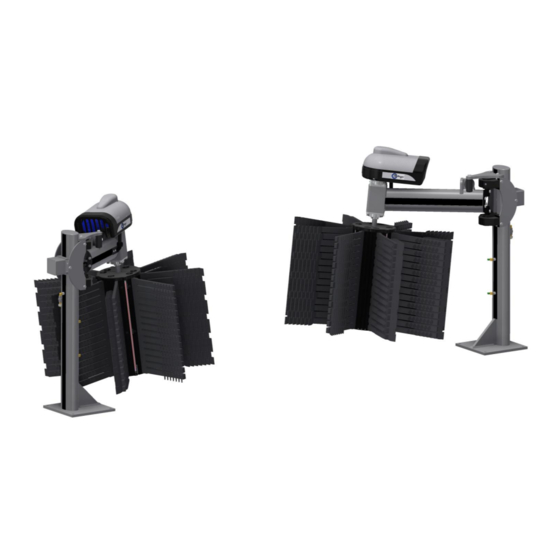
Cleaning Material Assembly SpinLite® Low Side Washer Hub Assembly Driver Side Assembly with LED Lights SpinLite® Low Side Washer Passenger Side Assembly Belanger, Inc. * PO BOX 5470 * Northville, MI 48167-5470 * Ph (248) 349-7010 * Fax (248) 380-9681 1MANUL962... -
Page 14: Before You Get Started
SPINLITE® LOW SIDE WASHER Introduction Before You Get Started Below is a list of the SpinLite® Low Side Washer equipment you will receive in your shipment and the tools that are needed to install the equipment. Tools needed for installation:... -
Page 15: Specifications
A compressed Air System should be set correctly to support 90 PSI necessary to operate equipment, but should never be set to deliver more than 120 PSI air pressure to the Belanger specified equipment. Belanger, Inc. * PO BOX 5470 * Northville, MI 48167-5470 * Ph (248) 349-7010 * Fax (248) 380-9681 1MANUL962... -
Page 16: General Dimensions
SPINLITE® LOW SIDE WASHER Specifications General Dimensions Equipment Envelope 68” Top View 157” Entrance View 51” 13” Conveyor: 106” 52-1/2” 14-1/2” Conveyor: Belanger, Inc. * PO BOX 5470 * Northville, MI 48167-5470 * Ph (248) 349-7010 * Fax (248) 380-9681 1MANUL962... -
Page 17: Inspection
Cable 3) The Motor and LED cables are ready to be connected to their Main Power source after installation. Belanger, Inc. * PO BOX 5470 * Northville, MI 48167-5470 * Ph (248) 349-7010 * Fax (248) 380-9681 1MANUL962... -
Page 18: Hub Led Electrical Connections
Equipment to Inspect Before Installation Hub LED Electrical Connections Each SpinLite® LSW assembly has an electrical Slip Ring and Wire Harness to power the LEDs on the Hub. All electrical connections: power cable to Slip Ring, Slip Ring to Wire Harness, and Wire Harness to LEDs need to be inspected. - Page 19 Wire Harness LEDs 6) Remove one of the Hub Skins on each of the SpinLite® LSW Hub Assembly to gain access to the Wire Harness and LED wires, see image above right. 7) Locate the Wire Harness to Slip Ring connection and the four (4) LED connections.
- Page 20 LED Connections are above the Hub Spider. 10) Reinstall the Hub Skins and Hub Covers onto the Hubs assemblies. Belanger, Inc. * PO BOX 5470 * Northville, MI 48167-5470 * Ph (248) 349-7010 * Fax (248) 380-9681 1MANUL962...
-
Page 21: Installation
Installation Identify Conveyor The SpinLite® Low Side Washer assemblies can be installed in a tunnel with a Belanger® 13” or 14-1/2” wide Conveyor that has either a single or double guide rail. Identifying the conveyor is crucial for properly positioning the Low Side Washer assemblies during installation. The Belanger® conveyor options are shown in the images below. -
Page 22: Tunnel Placement: Overview
Installation Tunnel Placement: Overview When placing the SpinLite® Low Side Washer assemblies, tunnel depth will vary from site to site. Be sure to allow an adequate operating envelope. There are two traditional installation configurations for the SpinLite® Low Side Washer assemblies. -
Page 23: Staggered, With Quickfire® Plus Assemblies
Note: The above image is shown with cleaning material installed to indicate the operating envelope required for proper function. Belanger, Inc. * PO BOX 5470 * Northville, MI 48167-5470 * Ph (248) 349-7010 * Fax (248) 380-9681 1MANUL962... -
Page 24: Tunnel Placement: Preparation
52-1/2” if the conveyor is 14-1/2” wide. Refer to the image below. Driver Side DIRECTION TRAVEL 51” 13” Conveyor: 52-1/2” 14-1/2” Conveyor: Belanger, Inc. * PO BOX 5470 * Northville, MI 48167-5470 * Ph (248) 349-7010 * Fax (248) 380-9681 1MANUL962... - Page 25 SpinLite® Low Side Washer 5/8” Lag Bolts (4) 7) Next, position the passenger side SpinLite® Low Side Washer assembly in the tunnel so that it is aligned with the driver side unit. 8) Place the passenger side SpinLite® Low Side Washer assembly so that the outside edge of its baseplate is 106”...
-
Page 26: Tunnel Placement: Staggered Installation With Quickfire® Plus
1) Assuming that the QuickFire® Plus assemblies have already been installed per the QuickFire® Plus Manual 1MANUL830. 2) Refer to the image below, place the driver side SpinLite® LSW so that the front edge of its baseplate is 150” from the front edge of the driver side QuickFire® Plus baseplate. Also, the outside edge of the baseplate should be 51”... - Page 27 Installation Tunnel Placement: Staggered Installation with QuickFire® Plus 4) Once the driver side and passenger side SpinLite® LSW assemblies are in place verify that they are square to the conveyor. 5) Check to make sure they are level by placing a torpedo level on the pivot arms; rotate the arm while checking the level to confirm that the arms remain level throughout their entire range of motion.
-
Page 28: Loading Shinemitt™ Material On Hubs
2) Locate the ShineMitt™ Cleaning Material. There should be a total of 80 pieces of the Short Lead ShineMitt™ (111060) for the SpinLite® Low Side Washer assemblies. Clips ShineMitt™ Short Lead: 111060 Belanger, Inc. * PO BOX 5470 * Northville, MI 48167-5470 * Ph (248) 349-7010 * Fax (248) 380-9681 1MANUL962... - Page 29 TRAVEL Driver Side Passenger Side 5) The ShineMitt™ for the driver side SpinLite® LSW must be assembled as shown in the image below on the left; there must be 40 pieces of the ShineMitt™ assembled this way. Passenger Side Driver Side ShineMitt™...
- Page 30 15) Insert the ShineMitt™ into the first and last slot of each Hub Skin section this fill pattern is shown in the images above. Belanger, Inc. * PO BOX 5470 * Northville, MI 48167-5470 * Ph (248) 349-7010 * Fax (248) 380-9681 1MANUL962...
- Page 31 19” - 45 DEG Short Lead 19) After the ShineMitt™ material is loaded reinstall the Hub Covers onto the Hub assemblies. Belanger, Inc. * PO BOX 5470 * Northville, MI 48167-5470 * Ph (248) 349-7010 * Fax (248) 380-9681 1MANUL962...
-
Page 32: Utilities
Water Connections: Water Line to the SpinLite® Low Side Washers At this point, the SpinLite® LSW assemblies have been installed in the tunnel and are ready to be connected to the utilities. Begin by routing and connecting the water lines to the LSW assemblies. - Page 33 Installation Utilities Water Connections: Water Line to the SpinLite® Low Side Washers 5) Locate the four (4) 1/2” Hose Clamps in the Accessory Box that came with the SpinLite® LSW assemblies. 1/2” Hose Clamps 6) Using the Hose Clamps secure the 1/2" water hoses to the tee fitting and route them to the driver side and passenger side SpinLite®...
-
Page 34: Pneumatic Connections: Air Panel To Cylinders
120-PSI maximum 20 PSI 40 PSI 2) Label the Air Panel for the SpinLite® LSW. All labels for the Air Panel are to be field supplied. 3) Use 1/4” field supplied black poly-flow airlines for extending the Cylinders and 1/4” field supplied gray poly-flow airlines for retracting the Cylinders on the SpinLite®... - Page 35 DS & PS Arm Cylinder 9) Cut the gray Retract Airline and insert a field supplied 1/4" tee fitting into the line. Belanger, Inc. * PO BOX 5470 * Northville, MI 48167-5470 * Ph (248) 349-7010 * Fax (248) 380-9681 1MANUL962...
-
Page 36: Electrical Connections: Air Panel To Controller
It is recommended that a licensed electrician is contracted to perform all electrical installations. All utilities MUST be installed in accordance with all local and national codes. Belanger, Inc. * PO BOX 5470 * Northville, MI 48167-5470 * Ph (248) 349-7010 * Fax (248) 380-9681 1MANUL962... -
Page 37: Pneumatic Connections: Initial Air Settings For Air Panel
Ride on the Air Panel Retract Valve, see above, or by using the flow control valve on the Cylinder Retract Port on each of the SpinLite® LSW assemblies. Start with Flow Controls set wide open. Belanger, Inc. * PO BOX 5470 * Northville, MI 48167-5470 * Ph (248) 349-7010 * Fax (248) 380-9681 1MANUL962... -
Page 38: Electrical Connections: Motor
575 VAC 460 VAC On the SpinLite® LSW assemblies, the motor wire has been routed from the motor through the Arm to the Leg and into the Junction Box, where they are ready to be connected to the main power source. - Page 39 5) If the wheels are not rotating in the proper direction then reverse the two leads to the Motors on the overload located in the Control Panel. Belanger, Inc. * PO BOX 5470 * Northville, MI 48167-5470 * Ph (248) 349-7010 * Fax (248) 380-9681 1MANUL962...
- Page 40 2) Remove the covers on the motors, make the changes to the wire connections and reinstall the motor covers. Motor Cover Image Showing Motor Wiring for Delta Motor Wiring Diagram Belanger, Inc. * PO BOX 5470 * Northville, MI 48167-5470 * Ph (248) 349-7010 * Fax (248) 380-9681 1MANUL962...
- Page 41 7) If the wheels are not rotating in the proper direction then reverse the two leads to the Motors on the overload located in the Control Panel. 8) Reattach the Top Cover to Gearbox/Motor Assemblies. Belanger, Inc. * PO BOX 5470 * Northville, MI 48167-5470 * Ph (248) 349-7010 * Fax (248) 380-9681 1MANUL962...
-
Page 42: Maintenance
S.O.S. pads and wash with a good degrimer such as Tide laundry detergent and hot water. Whenever using steel wool on aluminum, always follow the grain to prevent scratching the finish. Belanger, Inc. * PO BOX 5470 * Northville, MI 48167-5470 * Ph (248) 349-7010 * Fax (248) 380-9681 1MANUL962... -
Page 43: Troubleshooting
Verify all wires are secured to the drive shaft and there is adequate clearance between the wires and hub skins to prevent wear on the wires Belanger, Inc. * PO BOX 5470 * Northville, MI 48167-5470 * Ph (248) 349-7010 * Fax (248) 380-9681 1MANUL962... -
Page 44: Exploded Parts View
Assembly are the same for both Driver and Passenger Side SpinLite® Low Side Washer assemblies except where noted. Silver PC: 111733 Aluminum: 110829 1ELECT-FS750 1WASHR-LC456 (6) 1FSTNR-HH540 (6) Belanger, Inc. * PO BOX 5470 * Northville, MI 48167-5470 * Ph (248) 349-7010 * Fax (248) 380-9681 1MANUL962... -
Page 45: Manifold Assembly
SpinLite ® Low Side Washer assemblies. 1ELBOW-BR381 9066 108648 1MCONC-SS015 (2) Complete Manifold Assembly Driver Side: 108655 Passenger Side: 110043 1ELBOW-BR360 (2) 1NOZZL-FJ696 (2) 1PLUG-BR200 Belanger, Inc. * PO BOX 5470 * Northville, MI 48167-5470 * Ph (248) 349-7010 * Fax (248) 380-9681 1MANUL962... -
Page 46: Arm Assembly: Overview
Black PC: 10384 Aluminum: 10379 1NUT-RG603 Black PC: 111725 Aluminum: 111723 1WASHR-PL500 (2) 1BSHNG364 Black PC: 8311 Aluminum: 1034 1WASHR-FL415 (2) 1NUT-LC210 Belanger, Inc. * PO BOX 5470 * Northville, MI 48167-5470 * Ph (248) 349-7010 * Fax (248) 380-9681 1MANUL962... -
Page 47: Driver Side Arm Assembly: Pivot Shaft, Bearing Assemblies & Electrical Cables
Shaft Assembly are the same for both Driver and Passenger Side SpinLite® 9724 Low Side Washer assemblies. 9793 1STEEL-KY150 1COLLAR333 2 Halves & Fasteners Belanger, Inc. * PO BOX 5470 * Northville, MI 48167-5470 * Ph (248) 349-7010 * Fax (248) 380-9681 1MANUL962... -
Page 48: Passenger Side Arm Assembly: Cylinder Assembly & Electrical Cables
Cylinder Assembly see image above Passenger Side: Silver PC: 111730 Aluminum: 111728 1BERNG849 (2) 1RETNR129 1FSTNR-SB125 1FSTNR-SB725 1BSHNG364 1WASHR-LC581 (4) 1FSTNR-HH714 (4) Belanger, Inc. * PO BOX 5470 * Northville, MI 48167-5470 * Ph (248) 349-7010 * Fax (248) 380-9681 1MANUL962... -
Page 49: Motor Gearbox & Torque Plate Assembly
Motor Gearbox & Torque Plate Assembly: 110935 (2): 208/230V 110967 (2): 575V 7912 108661 1FSTNR-FH075 (8) Slip Ring Assembly: 110708 (2) 1FSTNR-SB093 110709 1GRMIT100 1NUT-RG335 Belanger, Inc. * PO BOX 5470 * Northville, MI 48167-5470 * Ph (248) 349-7010 * Fax (248) 380-9681 1MANUL962... -
Page 50: Motor/Gearbox, Drive Shaft & Cover Assembly
See image on right 1WASHR-LC125 (3) for part numbers 1FSTNR-HH045 (3) 7203 (2) & 1WASHR-LC581 (2) 1FSTNR-HH714 (2) & 1BERNG849 1WASHR-LC581 (2) Belanger, Inc. * PO BOX 5470 * Northville, MI 48167-5470 * Ph (248) 349-7010 * Fax (248) 380-9681 1MANUL962... -
Page 51: Hub Assembly: Overview
SPINLITE® LOW SIDE WASHER Maintenance Exploded Parts View Hub Assembly: Overview Upper Spider Assembly: 110713: Lower Spider Assembly: 111352: Complete Hub Assembly: 110703 Belanger, Inc. * PO BOX 5470 * Northville, MI 48167-5470 * Ph (248) 349-7010 * Fax (248) 380-9681 1MANUL962... -
Page 52: Hub Assembly: 110703 (2)
Bore Spider Assembly See Enlarged View Below 1FSTNR-HH350 1FSTNR-HH504 (4) 1WASHR-LC498 (4) 111351 (2) 111350 (2) 1NUT-LC214 111352: Lower Spider Assembly Belanger, Inc. * PO BOX 5470 * Northville, MI 48167-5470 * Ph (248) 349-7010 * Fax (248) 380-9681 1MANUL962... -
Page 53: Hub Shinemitt™ Fill Pattern
111060 (Qty. 8 per Hub) 19” - 45 DEG Short Lead 111060 (Qty. 8 per Hub) 19” - 45 DEG Short Lead Belanger, Inc. * PO BOX 5470 * Northville, MI 48167-5470 * Ph (248) 349-7010 * Fax (248) 380-9681 1MANUL962... -
Page 54: Shinemitt™ Short Lead: 111060 (Qty. 80)
And, 40 pieces must be assembled as shown in the image below for the passenger side LSW. 1PLSTC-CL010 (2) 10010 9985 (21) 1PIN-SS250 ShineMitt™ Assembly for Passenger Side LSW Belanger, Inc. * PO BOX 5470 * Northville, MI 48167-5470 * Ph (248) 349-7010 * Fax (248) 380-9681 1MANUL962... -
Page 55: Hub Cover Assembly: 110763 (2)
(one per Low Side Washer Assembly) LED RGB Assembly: 110764 (one per Low Side Washer Assembly) LED RGB Assembly: 110764 (2) 110962 (4) 110718 Belanger, Inc. * PO BOX 5470 * Northville, MI 48167-5470 * Ph (248) 349-7010 * Fax (248) 380-9681 1MANUL962... -
Page 56: Filler Strips For Driver Side
9808 8148 1PLSTC-EX062 110768 * Includes both DS Length 8” 29-3/16” 2” 42-1/4” 7” 2-1/2” 14-1/2” 15-1/8” & PS Filler Strips Belanger, Inc. * PO BOX 5470 * Northville, MI 48167-5470 * Ph (248) 349-7010 * Fax (248) 380-9681 1MANUL962... -
Page 57: Filler Strips For Passenger Side
9800 8148 8128 110768 * Includes both DS Length 8” 29-3/16” 2” 42-1/4” 7” 7-1/2” 14-1/2” 29-13/16” & PS Filler Strips Belanger, Inc. * PO BOX 5470 * Northville, MI 48167-5470 * Ph (248) 349-7010 * Fax (248) 380-9681 1MANUL962... -
Page 58: Air Panel: 102060
1DECAL-MF045 RETRACT DRIVER SIDE 1DECAL-MF250 LOW SIDE 1MADAP-BR600 WASHER 1WASHR-LC115 (6) 1VALVE-EL710 1FSTNR-SH177 (6) 1FSTNR-HH081 (2) 120 VAC 1WASHR-LC125 (2) 1MADAP-BR600 Belanger, Inc. * PO BOX 5470 * Northville, MI 48167-5470 * Ph (248) 349-7010 * Fax (248) 380-9681 1MANUL962...
Need help?
Do you have a question about the SpinLite and is the answer not in the manual?
Questions and answers