Table of Contents
Advertisement
Quick Links
MS125 Series Installation Guide
About this Guide
This guide provides instruction on how to install and configure your MS125 series switch. This guide also provides mounting instructions and limited
troubleshooting procedures. For more switch installation guides, refer to the
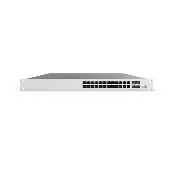
Model number
MS125-24
Layer-2 24-port gigabit Ethernet switch with 4 SFP+ interfaces
MS125-24P
Layer-2 24-port gigabit Ethernet 370W PoE switch with 4 SFP+ interfaces
MS125-48
Layer-2 48-port gigabit Ethernet switch with 4 SFP+ interfaces
MS125-48LP
Layer-2 48-port gigabit Ethernet 370W PoE switch with 4 SFP+ interfaces
MS125-48FP
Layer-2 48-port gigabit Ethernet 740W PoE switch with 4 SFP+ interfaces
Product Overview
Physical Specifications
1GbE RJ45
10GbE SFP+
Dedicated Mgmt Interface
PoE Capable
Power Supply
switch installation guides section
Description
MS125-24
MS125-24P
24
4
1
-
Yes, 370W
Built-in
on our documentation website.
MS125-48
24
4
1
Built-in
Built-in
MS125-48LP
48
48
4
1
-
Yes, 370W
Built-in
4
1
1
Advertisement
Table of Contents

Related Manuals for Cisco Meraki MS125 Series


Summary of Contents for Cisco Meraki MS125 Series
- Page 1 MS125 Series Installation Guide About this Guide This guide provides instruction on how to install and configure your MS125 series switch. This guide also provides mounting instructions and limited troubleshooting procedures. For more switch installation guides, refer to the switch installation guides section on our documentation website.
- Page 2 Fans Built-in Built-in 100 - 240 VAC, 100 - 240 VAC, 100 - 240 VAC, 100 - 240 VAC, Power Input 47-63 Hz 47-63 Hz 47-63 Hz 47-63 Hz 10.3 - 25.6 W 21.7 - 42W 25 - 426.1W 40.2 - 439.8W Power Consumption Power Load (idle/max) 10.3/ 25.6 W...
- Page 3 MS125-48 Series front panel MS125-48LP/FP Series front panel ms125-48P.png Back Panel MS125 Series back panel Factory Reset Button If the button is pressed and held for at least five seconds and then released, the switch will reboot and be restored to its original factory settings by deleting all configuration information stored on the unit.
- Page 4 Switch Ports No link is detected on this port Flashing orange (RJ45 ports only) Activity indicator Solid green 1 Gbps link detected In addition, there is a RESTORE button available on the front panel. Insert a paperclip if a restore is required. •...
-
Page 5: Package Contents
Package contents In addition to the MS switch, the following are provided: ▪ US 12-24 mounting screws and cage nuts, 5 of each ▪ INTL M5 mounting screws and cage nuts, 5 of each ▪ INTL M6 mounting screws and cage nuts, 5 of each ▪... -
Page 6: Pre-Install Preparation
Safety and Warnings These operations are to be taken with respect to all local laws. Please take the following into consideration for safe operation: • Power off the unit before you begin. Read the installation instructions before connecting the system to the power source. -
Page 7: Installation Instructions
for your particular organization can be found on the firewall configuration page in your dashboard. Assigning an IP Address All switches must be assigned routable IP addresses. These IP addresses can be dynamically assigned via DHCP or statically assigned. Dynamic Assignment When using DHCP, the DHCP server should be configured to assign a static IP address for each MAC address belonging to a Meraki switch. - Page 8 2. Attach the switch face plate to the cage nuts on the rack.
- Page 9 3. Connect power to the power supply unit.
-
Page 10: Basic Troubleshooting
ms125_page_three.png 4. (Optional) Install additional SFP+ units as needed, depending on the compatibility of your model. Mounting hardware The mounting hardware includes a rack mount kit for standard 1U racks. When installing the device, make sure that there is sufficient space between the rear of the rack and other obstacles to ensure adequate airflow. -
Page 11: Warranty
If you are still experiencing hardware issues, please contact Cisco Meraki support by logging in to dashboard and using the Help option near the top of the page, then opening and email case or calling using the contact information on that page. - Page 12 • The equipment is subject to installation and maintenance by specialists with the appropriate qualifications, sufficient specialized knowledge, and skills. • Rules and conditions for the sale of equipment are determined by the terms of contracts concluded by Cisco or authorized Cisco partners with equipment buyers.
Need help?
Do you have a question about the Meraki MS125 Series and is the answer not in the manual?
Questions and answers