Cisco Meraki MS225 Series Installation Manual
Hide thumbs
Also See for Meraki MS225 Series:
- Setup instruction (6 pages) ,
- Installation manual (4 pages)
Advertisement
Table of Contents
- 1 Front Panel
- 2 Back Panel
- 3 Factory Reset Button
- 4 Ports and Status Indicators
- 5 RPS2300 Redundant Power Supply (Optional)
- 6 Package Contents
- 7 Safety and Warnings
- 8 Pre-Install Preparation
- 9 Assigning an IP Address
- 10 Dynamic Assignment
- 11 Static Assignment
- 12 Installation Instructions
- 13 Mounting Hardware
- 14 Basic Troubleshooting
- 15 Bringing Your Stack Online
- 16 Warranty
- Download this manual
MS225 Series Installation Guide
About this Guide
This guide provides instruction on how to install and configure your MS225 series switch. This guide also provides
mounting instructions and limited troubleshooting procedures. For more switch installation guides, refer to the
switch installation guides section
Model number
MS225-24
Stackable Layer-2 24-port gigabit Ethernet switch with 4 SFP+ interfaces
Stackable Layer-2 24-port gigabit Ethernet 370W PoE switch with 4 SFP+
MS225-24P
interfaces
MS225-48
Stackable Layer-2 48-port gigabit Ethernet switch with 4 SFP+ interfaces
Stackable Layer-2 48-port gigabit Ethernet 370W PoE switch with 4 SFP+
MS225-48LP
interfaces
Stackable Layer-2 48-port gigabit Ethernet 740W PoE switch with 4 SFP+
MS225-48FP
interfaces
Product Overview
Physical Specifications
on our documentation website.
Description
MS225-24
MS225-24P
MS225-48
MS225-48LP
MS2
1
Advertisement
Table of Contents

Related Manuals for Cisco Meraki MS225 Series


Summary of Contents for Cisco Meraki MS225 Series
- Page 1 MS225 Series Installation Guide About this Guide This guide provides instruction on how to install and configure your MS225 series switch. This guide also provides mounting instructions and limited troubleshooting procedures. For more switch installation guides, refer to the switch installation guides section on our documentation website.
-
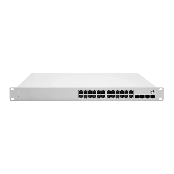
Page 2: Front Panel
1GbE RJ45 10GbE SFP+ 10G Hardware Stack Port Dedicated Mgmt Interface PoE/PoE+ Capable Yes, 370W Yes, 370W Power Supply Fixed Internal Fixed Internal Fixed Internal Fixed Internal Fixe External RPS* External RPS* External RPS* External RPS* Exte Redundant Power Supply (optional) (optional) (optional) -
Page 3: Back Panel
MS225-24 Series front panel MS225-48 Series front panel Back Panel MS225 Series back panel Factory Reset Button If the button is pressed and held for at least five seconds and then released, the switch will reboot and be restored to its original factory settings by deleting all configuration information stored on the unit. -
Page 4: Rps2300 Redundant Power Supply (Optional)
Equipment is to be used only in a restricted access location and installed/operated only by trained service personnel. RPS2300 Redundant Power Supply (Optional) The MS225 series supports connecting the Cisco RPS2300 for optional power redundancy. MS225 series models support failover and reversion to main power once it has been restored. The following Cisco part numbers are supported:... -
Page 5: Package Contents
Part number Description PWR-RPS2300 RPS Chassis C3K-PWR-750WAC 750W RPS Power supply (see recommendations) C3K-PWR-1150WAC 1150W RPS Power supply (see recommendations) CAB-RPS2300-E= RPS 22-pin cable RPS power supply matrix Switch Model Full power load [idle/max including PoE] MS225-24 15 / 24 W MS225-24P 21 / 448 W MS225-48... -
Page 6: Safety And Warnings
▪ Mounting washers Note: MS225 does not include stacking cables. Stacking cables sold separately. Safety and Warnings These operations are to be taken with respect to all local laws. Please take the following into consideration for safe operation: • Power off the unit before you begin. Read the installation instructions before connecting the system to the power source. -
Page 7: Assigning An Ip Address
2. The switch will turn on and the power LED will glow solid orange. 3. If the unit requires an upgrade, the power LED will begin blinking white until the upgrade is complete, at which point the LED will turn solid white. You should allow at least a few minutes for the firmware upgrade to complete, depending on the speed of your internet connection. -
Page 8: Installation Instructions
Installation Instructions Note: Each switch comes with a graphical instruction pamphlet within the box. This pamphlet contains detailed step by step guides and images to assist in the physical install of the switch. 1. Install the mounting cage nuts in the rack being used for the switch. 2. - Page 9 3. Attach the rack mount rail to the sides of the switch.
- Page 10 4. Insert the rack mount rail into the rack mount rail channel.
- Page 11 5. Attach the switch face plate to the cage nuts on the rack.
- Page 12 6. Secure the rack mount rail to the rack mount rail channel.
-
Page 13: Mounting Hardware
7. (Optional) Install additional SFP+, QSFP+ or QSFP28 units as needed, depending on the compatibility of your model. Mounting hardware The mounting hardware includes a rack mount kit for standard 1U racks. When installing the device, make sure that there is sufficient space between the rear of the rack and other obstacles to ensure adequate airflow. Optional Mid-Mount bracket MS225 48 port models are designed for an optional MA-MNT-MID-1 mid-mount bracket when using 2-post racks. -
Page 14: Bringing Your Stack Online
If you are still experiencing hardware issues, please contact Cisco Meraki support by logging in to dashboard and using the Help option near the top of the page, then opening and email case or calling using the contact information on that page. - Page 15 Additional warranty information can be found on: https://meraki.cisco.com/support#process:warranty Support and Additional Information If issues are encountered with device installation or additional help is required, contact Meraki Support by logging in to dashboard.meraki.com and opening a case by visiting the Get Help section.
Need help?
Do you have a question about the Meraki MS225 Series and is the answer not in the manual?
Questions and answers