Table of Contents
Advertisement
Quick Links
Advertisement
Table of Contents

Related Manuals for ChlorKing ChlorSM Series


Summary of Contents for ChlorKing ChlorSM Series
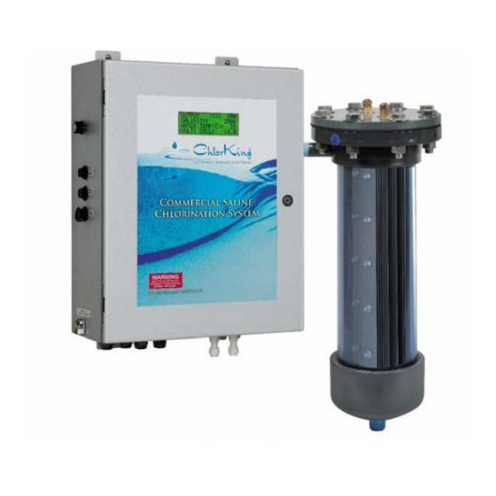
- Page 1 ChlorSM Series SALINE CHLORINATOR Installation, Operation, and Maintenance Manual...
-
Page 2: Table Of Contents
4.0 MAINTENANCE Acid Wash Operation 5.0 WARRANTY INFORMATION Note: This manual is subject to change at any time based on system improvements, design changes, authorized modifications or new information. Please consult ChlorKing for the latest revision. Manufacturer: ChlorKing Inc 6767 Peachtree Industrial Blvd. -
Page 3: Description
The system manufactures bleach continuously from a salt concentration of 3500 to 5000 ppm added to the pool. The ChlorKing® system is designed for commercial service and can be operated 24 hours a day or controlled by any pool controller. All models have digital displays that show system status, pool salt concentration, and temperature. -
Page 4: General Specifications And Sizing Guidelines
ChlorKing® Acid Wash The ChlorKing® Classic SM System (non-reverse polarity) is supplied with a clean in place Acid Wash System. The clean in place Acid Wash System makes cell maintenance quick and easy. 1.3 GENERAL SPECIFICATIONS SODIUM HYPOCHLORITE PRODUCTION: Sodium... - Page 5 SPACE REQUIREMENTS: CHLOR7.5CSM AND CHLOR10.0CSM 6" Cell Tube DC Power to Cell Cooling Water Lines CHLOR7.5SM AND CHLOR10.0SM 6" Cell Tube DC Power to Cell Cooling Water Lines SM Install Manual Page 5 of 35 05/05/2016...
- Page 6 CHLOR15.0SM, CHLOR15.0CSM, CHLOR20.0CSM, AND CHLOR25.0CSM 6" Cell Tube DC Power to Cell Cooling Water Lines CHLOR20.0SM AND CHLOR25.0SM 8" Cell Tube DC Power to Cell Cooling Water Lines SM Install Manual Page 6 of 35 05/05/2016...
- Page 7 SIZING GUIDELINES Chlorinator sizing must comply with local codes. Please contact your local health department for specific requirements or contact your local ChlorKing® representative for assistance. HEAD LOSS DATA 100.00 Head Loss Data for Chlor-25.0C. 90.00 88.6 80.00 Head loss data reported in ft 70.00...
-
Page 8: Installation
ANY SERVICING OF THIS EQUIPMENT MUST BE DONE WITH THE UNIT FULLY OFF AND DISCONNECTED FROM THE POWER SOURCE AND ALL PRESSURE BLED FROM THE LIQUID LINES. WARNING CHLORKING® SYSTEMS ARE INTENDED TO BE INSTALLED ACCORDING TO ALL LOCAL AND NATIONAL REGULATIONS. - Page 9 AUCUNE OPÉRATION DE MAINTENANCE DE CET ÉQUIPEMENT DOIT ÊTRE FAITE AVEC L'UNITÉ ENTIÈREMENT ÉTEINT ET DÉBRANCHÉE DE L'ÉLECTRICITÉ ET TOUTE LA PRESSION SAIGNÉ À PARTIR DES LIGNES DE LIQUIDES. MISE EN GARDE CHLORKING ® SYSTEMES SONT DESTINES A ETRE INSTALLES SELON TOUS LES REGLEMENTS LOCAUX ET NATIONAUX.
-
Page 10: Plan Ahead
CONNECTER LE MONTAGE DE L'ÉQUIPEMENT SUR UN CIRCUIT PROTÉGÉ PAR UN DISJONCTEUR DE FUITE À LA TERRE. SEUL UN TECHNICIEN CERTIFIE PEUT INSTALLER ET ENTRETENIR LE CHLORKING ® SYSTEM. MODIFIANT LA CHLORKING ® SYSTEM EN QUELQUE SORTE PEUT CAUSER ... -
Page 11: Installation Diagram
2.6 INSTALLATION DIAGRAM Controller Power Supply Disconnect Ball Valve Control Cord Rated VAC In See Table Bonding Lug Power Supply Cooling Line Flow Sensor Strainer Salt Sensor Ball Valve Waste Line Filter Heat Exchanger Return Line Pump Ball Valve Pump ( Optional) Suction Line From Pool SM Install Manual... -
Page 12: Power Supply Installation
2.7 POWER SUPPLY INSTALLATION WARNING THE MOUNTING LOCATION OF THE UNIT MUST BE AT LEAST 1.5 METERS FROM THE POOL. NEVER TRY TO SUPPORT THE WEIGHT OF THE POWER SUPPLY OR ELECTROLYTIC CELL USING ONLY DRYWALL ANCHORS. Locate a space on the wall, in the equipment room, that will accommodate the dimensions of the system. -
Page 13: Install Kit Installation
2.9 INSTALL KIT INSTALLATION Install the parts found in the installation kit in the order shown in the following diagram. NOTE: The flow switch must be installed with the arrow facing the bottom of the cell tube. Chlor7.5SM, Chlor10.0SM, Chlor15.0SM Assembly Diagram SM Install Manual Page 13 of 35... - Page 14 Chlor20.0SM, Chlor25.0SM Assembly Diagram SM Install Manual Page 14 of 35 05/05/2016...
- Page 15 Chor7.5CSM, Chlor10.0CSM, Chlor15.0CSM, Chlor20.0CSM, Chlor25.0CSM Assembly Diagram SM Install Manual Page 15 of 35 05/05/2016...
-
Page 16: Plumbing The System
2.10 PLUMBING THE SYSTEM Chlorking® systems require a minimum of 20 gpm of flow through the electrolytic cell to achieve the rated production of chlorine. The cell housing is plumbed using a bypass to achieve the 20 gpm of flow required. The cell housing must be installed as the last component in the return line of the pool, after all other equipment. -
Page 17: System Wiring
CONNECTED. THE ELECTRICAL SUPPLY MUST MATCH THE SYSTEM RATED VOLTAGE AND CURRENT. ENSURE THAT POWER IS LINKED TO THE MAIN PUMP POWER SOURCE FOR THE POOL TO ENSURE THAT THE CHLORKING® SYSTEM NEVER OPERATES WHEN THE POOL PUMPS ARE OFF. - Page 18 15.0 Through 25.0: 208/240V Only Ground Line 2 (Green) (Red) Line 1 (Black) Connect the blue control cord to a chemical feed controller or for manual operation, to a 120 volt AC outlet. When connecting to a chemical feed controller, be sure the controller is set to continuous feed and not set on proportional control.
-
Page 19: Instructions For Adding A Salt Feed Relay
2.15 BONDING THE SYSTEM All ChlorKing® systems include cell-bonding assemblies. These assemblies are included in the install kit. The bonding assemblies must be connected with a minimum of 8 AWG bonding wire. Connect the bonding wire from the top cell grounding assembly to the bottom cell grounding assembly and then from the bottom cell grounding assembly to the bonding lug located on the outside of the power supply. -
Page 20: Operation
Once the salt has been added, brush the surface of the pool continuously until the salt has dissolved. Never leave large amounts of salt on the surface of the pool. Only use pure NACl. Do not use salt with additives. Contact your dealer or ChlorKing® for a list of approved salt. -
Page 21: System Operation
Depending on the model, the system will begin producing chlorine in 10 to 60 seconds. If the ChlorKing® system is linked to a chemical feed controller, adjust the output to the system maximum, which will allow for full production every time the controller calls for it. If the system is being operated manually, adjust the system to find the point at which chlorine levels are maintained to the desired level. - Page 22 This sceen is displayed when the system is waiting for a signal on the blue cord from an external source such as a chemical feed controller. The system will not generate chlorine until this signal is received. The screen below is displayed when the system detects no flow through the electrolytic cell housing.
- Page 23 This screen is displayed if a low salt condition is present. Any salt concentration below 3000 ppm will stop the system output and display this screen. When the salt concentration is raised above 3000 ppm, normal system operation will resume. This screen will be displayed if water temperature drops below 59º...
- Page 24 The screen below indicates a disconnected or defective salt sensor. This screen will shut the system output off. Reconnect or replace the salt sensor to restore system operation. In order to prevent the system from being cycled on and off rapidly, the system has start delay of 60 seconds.
- Page 25 The following screens are available by accessing the micro controller inside of the power supply. WARNING THE POWER SUPPLY CONTAINS HIGH VOLTAGE CIRCIUTS THAT CAN CAUSE INJURY OR DEATH. ONLY PERSONS CERTIFIED AND TRAINED TO SERVICE THESE UNITS SHOULD ACCESS THE FOLLOWING SCREENS. WHEN MAINTAINING THIS EQUIPMENT, KEEP SAFETY CONSIDERATIONS FOREMOST.
- Page 26 This system is capable of controlling the salt concentration of the pool with the addition of an external relay. The factory set point for salt is 5000 ppm. The salt set point can be adjusted to any value between 3000 and 7000 ppm. To access the salt set point screen, press and hold the “B”...
-
Page 27: Maintenance
SECTION 4 MAINTENANCE ChlorKing® systems are designed to operate 24 hours a day and 7 days a week at maximum production rates and will give you years of trouble free use if you follow these basic maintenance and cleaning instructions. - Page 28 Evaluate the cell condition every week Visually inspect the cell tube for leaks and the cell stack for calcium build up. Check the connections at the top of cell and clean as needed. This electrode stack is in excellent condition and A cell stack with calcium bridged does not require cleaning plates.
- Page 29 Clean the cell when calcium buildup is present (reverse polarity systems) WARNING Read all cautions and directions provided with the muriatic acid used. Always add acid to water. Use only with adequate ventilation. If strong odor is noticed, STOP, ventilation is inadequate.
-
Page 30: Acid Wash Operation
Clean the cell when calcium buildup is present with the ChlorKing® Acid Wash System (non-reverse polarity system) WARNING Read all cautions and directions provided with the muriatic acid used. Always add acid to water. Use only with adequate ventilation. If strong odor is noticed, STOP, ventilation is inadequate. - Page 31 Connect the acid wash tank and pump to the acid wash valves [3] and [4] as shown in the photo on the right. Fill the acid wash tank with 4 gallons of water and 1 gallon of muriatic acid. Open the white wash valves [5] and [6]. Open the tank feed valve [7].
- Page 32 Close all acid wash valves [3], [4], [5], [6], [7], [8] and [9]. Open the 2 cell tube valves [1] and [2]. Restart the system. NOTE: All acid wash valves must be closed prior to restarting the system or damage to the acid wash tank may occur. Saline Chlorinator Install Manual Page 32 of 35 1/20/15...
- Page 33 Visually inspect the power supply once every month. Open the enclosure and visually check for any abnormal conditions such as burned wires, loose connections or corrosion. Operate the system to verify performance once every month. Turn the system on. Adjust the control knob to the full off position and note that the amps displayed on the meter go to zero.
-
Page 34: Warranty Information
ChlorKing® warranties of the titanium electrodes will not be honored if the system is operated in water temperatures lower than 59 degrees F. During the warranty period the customer shall return the defective component, freight prepaid, accompanied by the original invoice or proof of purchase, and ChlorKing®... - Page 35 Warranty Registration Card Please complete and return to activate ChlorKing® warranty Please mail or fax to ChlorKing® inc. P.O. Box 80823, Atlanta, GA, 30366 Fax: 770-685-6576 Dealer Name: _______________________________________________________ Address: _________________________________City:__________________ State: ______________________Zip:___________Tel:_____________________ Installation site of equipment:___________________________________________ Address: _________________________________City:__________________ State:...
Need help?
Do you have a question about the ChlorSM Series and is the answer not in the manual?
Questions and answers