Table of Contents

Subscribe to Our Youtube Channel
Related Manuals for ChlorKing CHLOR Series


Summary of Contents for ChlorKing CHLOR Series
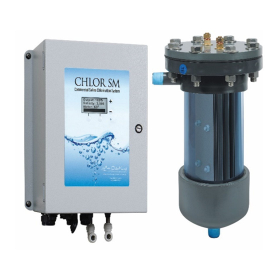
- Page 1 CHLOR SALINE CHLORINATOR Models covered in this manual: CHLOR2.0MSM, CHLOR3.0MSM, CHLOR5.0MMSM CHLOR7.5SM, CHLOR10SM. CHLOR12.5SM CHLOR15SM, CHLOR20SM, CHLOR25SM Installation, Operation Manual, and Parts Manual CHLORSM CHLORMSM...
- Page 2 2935 Northeast Parkway Atlanta, GA 30360 1-800-536-8180 This manual is subject to change at any time based on system improvements, design changes, authorized modifications, or new information. Please consult ChlorKing for the latest revision. CHLOR Install Manual Page 2 of 41 07/12/24...
-
Page 3: Table Of Contents
TABLE OF CONTENTS DESCRIPTION ............................. 4 GENERAL INFORMATION ........................4 PRINCIPALS OF OPERATION ......................5 GENERAL SPECIFICATIONS ......................6 INSTALLATION ............................11 UNPACKING ............................11 STORAGE ............................11 SAFETY CONSIDERATIONS ......................11 PLAN AHEAD ............................. 13 ADDITIONAL PARTS REQUIRED FOR INSTALLATION ..............13 INSTALLATION AND ASSEMBLY DIAGRAM .................. -
Page 4: Description
The system manufactures bleach continuously from a salt concentration of 3500 to 5000 ppm added to the pool. The ChlorKing® system is designed for commercial service and can be operated 24 hours a day or controlled by any pool controller. -
Page 5: Principals Of Operation
Salt Control Salt control can be added to the ChlorKing® SM Series Chlorinator. The ChlorKing® SM Series Chlorinator monitors the salt concentration of the pool water and will only allow the system to generate chlorine if the salt concentration is above 3000 ppm to protect the system from low salt. -
Page 6: General Specifications
GENERAL SPECIFICATIONS SODIUM HYPOCHLORITE PRODUCTION: Sodium Minimum Inlet Outlet Rated Hypochlorite Model Rated Water Diameter Diameter Power in Production Designation Pressure Flow Rate DC Amps (gpm) (lbs/day) (Inches) (Inches) CHLOR2.0MSM 2.2lbs/day 50 psi 20 gpm 1 inch ¾ inch CHLOR3.0MSM 3.0lbs/day 50 psi 20 gpm... -
Page 7: Electrical Requirements
ELECTRICAL REQUIREMENTS: Model AC Input Fuse GFCI Control Phases Frequency Amps Designation Voltage Size Breaker* Signal** 120v, 1amp CHLOR2.0MSM 50/60Hz 120v, 1amp CHLOR3.0MSM 50/60Hz 120v, 1amp CHLOR5.0MSM 50/60Hz 120v, 1amp CHLOR7.5SM 110 to 240 50/60Hz 15/7.5 120v, 1amp CHLOR10.0SM 110 to 240 50/60Hz 15/7.5 120v, 1amp... - Page 8 SPACE REQUIREMENTS: CHLOR2.0MSM, CHLOR3.0MSM, and CHLOR5.0MSM 600 W Power Supply 2.0lb Cell Tube 3.0lb Cell Tube 5.0lb Cell Tube CHLOR7.5SM, CHLOR10.0SM, and CHLOR12.5SM 7.5lb, 10.0lb, and 12.5lb Cell Tube 1200 W Power Supply 6 " C e l l T u b e D C P o w e r t o C e l l C o o l i n g W a t e r...
- Page 9 CHLOR15SM, CHLOR20.0SM, and CHLOR25.0SM 2400 W Power Supply 20lb and 25lb Cell Tube 15lb Cell Tube 6 " C e l l T u b e D C P o w e r t o C e l l C o o l i n g W a t e r L i n e s HLOR7.5CSM CHLOR10.0CSM...
-
Page 10: Sizing Guidelines
SIZING GUIDELINES Chlorinator sizing must comply with local codes. Please contact your local health department for specific requirements or contact your local ChlorKing® representative for assistance. HEAD LOSS DATA Head loss data reported in ft.H2O 1.20 1.089 1.00 Head Loss Data for 0.80... -
Page 11: Installation
AND DISCONNECTED FROM THE POWER SOURCE AND ALL PRESSURE BLED FROM THE LIQUID LINES. WARNING CHLORKING® SYSTEMS ARE INTENDED TO BE INSTALLED ACCORDING TO ALL LOCAL AND NATIONAL REGULATIONS. CONNECT THE EQUIPMENT ASSEMBLY TO A CIRCUIT PROTECTED BY A GROUND-FAULT CIRCUIT-INTERRUPTER. - Page 12 AUCUNE OPÉRATION DE MAINTENANCE DE CET ÉQUIPEMENT DOIT ÊTRE FAITE AVEC L'UNITÉ ENTIÈREMENT ÉTEINT ET DÉBRANCHÉE DE L'ÉLECTRICITÉ ET TOUTE LA PRESSION SAIGNÉ À PARTIR DES LIGNES DE LIQUIDES. MISE EN GARDE CHLORKING ® SYSTEMES SONT DESTINES A ETRE INSTALLES SELON TOUS LES REGLEMENTS LOCAUX ET NATIONAUX.
-
Page 13: Plan Ahead
CONNECTER LE MONTAGE DE L'ÉQUIPEMENT SUR UN CIRCUIT PROTÉGÉ PAR UN DISJONCTEUR DE FUITE À LA TERRE. SEUL UN TECHNICIEN CERTIFIE PEUT INSTALLER ET ENTRETENIR LE CHLORKING ® SYSTEM. MODIFIANT LA CHLORKING ® SYSTEM EN QUELQUE SORTE PEUT CAUSER ... -
Page 14: Installation And Assembly Diagram
INSTALLATION AND ASSEMBLY DIAGRAM Install the parts found in the installation kit in the order shown in the following diagram. NOTE: The flow switch must be installed with the arrow facing the bottom of the cell tube. Disconnect box or Outlet. - Page 15 Chor7.5CSM, Chlor10.0CSM, Chlor15.0CSM, Chlor20.0CSM, Chlor25.0CSM Assembly Diagram Classic SMPS, 6” Install Kit Acid Wash Installed Conductivity Controller Installed CHLOR Install Manual Page 15 of 41 07/12/24...
-
Page 16: Power Supply Installation
POWER SUPPLY INSTALLATION WARNING THE MOUNTING LOCATION OF THE UNIT MUST BE AT LEAST 1.5 METERS FROM THE POOL. NEVER TRY TO SUPPORT THE WEIGHT OF THE POWER SUPPLY OR ELECTROLYTIC CELL USING ONLY DRYWALL ANCHORS. Locate a space on the wall, in the equipment room, that will accommodate the dimensions of the system. -
Page 17: Plumbing The System
PLUMBING THE SYSTEM The ChlorKing® system is installed offline and requires a minimum of 20 gpm of flow through the electrolytic cell to achieve the rated production of chlorine. The installation requires a pressure differential to achieve 20 GPM flow. The cell housing must be installed as the last component in the return line of the pool, after all other equipment. - Page 18 7.5 Through 12.5: 110V 7.5 Through 12.5: 208/240V Line 1 Ground Line Ground (Black) (Green) Line 2 (Black) (Green) Neutral (Red) (White) 15.0 Through 25.0: 208/240V Only Ground Line 2 (Green) (Red) Line 1 (Black) CHLOR Install Manual Page 18 of 41 07/12/24...
-
Page 19: Bonding The System
BONDING THE SYSTEM All ChlorKing® systems include cell-bonding assemblies. These assemblies are included in the install kit. The bonding assemblies must be connected with a minimum of 8 AWG bonding wire. Connect the bonding wire from the top cell grounding assembly to the bottom cell grounding assembly and then from the bottom cell grounding assembly to the bonding lug located on the outside of the power supply. -
Page 20: Operation
Once the salt has been added, brush the surface of the pool continuously until the salt has dissolved. Never leave large amounts of salt on the surface of the pool. Only use pure NACl. Do not use salt with additives. Contact your dealer or ChlorKing® for a list of approved salt. -
Page 21: System Operation
Depending on the model, the system will begin producing chlorine in 10 to 60 seconds. If the ChlorKing® system is linked to a chemical feed controller, adjust the output to the system maximum, which will allow for full production every time the controller calls for it. If the system is being operated manually, adjust the system to find the point at which chlorine levels are maintained to the desired level. - Page 22 Waiting for Control Signal This sceen is displayed when the system is waiting for a signal on the blue cord from an external source such as a chemical feed controller. The system will not generate chlorine until this signal is received. MSM Models SM Models Countdown on Screen...
- Page 23 Salt Setpoint This system is capable of controlling the salt concentration of the pool with the addition of an optional external relay. The factory set point for salt is 5000 ppm. The salt set point can be adjusted to any value between 3000 and 7000 ppm. To access the salt set point screen on the MSM, select Menu then Setpoint to adjust.
-
Page 24: Troubleshooting
The data plate is located on the left side of the power box and shown below. ORDERING PARTS Parts can be ordered at www.chlorking.com/replacement-parts, by emailing service@chlorking.com or by calling 1-800-536-8180. You will need the system model number and system serial number to order parts. Please have these ready when you call. - Page 25 TROUBLESHOOTING CHLOR SCENERIO POSSIBLE CAUSE CORRECTIVE ACTION Confirm salt using a secondary method Improper testing method and add as directed by salt addition chart. Low Salt Possible leak in the vessel Consult leak detection for repair. Investigate daily & weekly procedures Extreme dilution or backwash and correct as needed.
-
Page 26: Maintenance
MAINTENANCE ChlorKing® systems are designed to operate 24 hours a day and 7 days a week at maximum production rates and will give you years of trouble free use if you follow these basic maintenance and cleaning instructions. This system produces sodium hypochlorite from the salt added to the water. It will only continue to operate correctly if salt is maintained at a minimum level of 3500 ppm. - Page 27 4. Evaluate the cell condition weekly. Visually inspect the cell tube for leaks and the cell stack for calcium build up. Check the connections at the top of cell and clean as needed. Clean when calcium build up is present. Instructions beginning on page 29.
- Page 28 Instructions for Cleaning the Cell on the following Pages WARNING Read all cautions and directions provided with the muriatic acid used. Always add acid to water. Use only with adequate ventilation. If strong odor is noticed, STOP, ventilation is inadequate. Leave area immediately.
- Page 29 Instructions for Cleaning the Cell with ChlorKing® Acid Wash System Acid Wash Operation Turn off the power to the chlorinator to be serviced. Close the lower and upper cell tube ball valves [1] and [2]. Always close the lower ball valve [1] first to avoid damaging the cell tube.
-
Page 30: Parts Guide
PARTS GUIDE CHLOR Installation Manual Page 30 of 41 July 2024... - Page 31 CHLOR2.0-3.0SM ITEM MODEL PART NUMBER DESCRIPTION QTY. CHLOR 2.0SM CH3MT CELL HOUSING 3" MICRO CHLOR 3.0SM CELL HOUSING 3” CHLOR 2.0SM ESTK2.0T ELECTRODE STACK 2.0T CHLOR 3.0SM ESTK3.0MSM ELECTRODE STACK 3.0MSM 439-131 3/4" X 1" BUSHING CELLGROUND CELL GROUND 1" 8058-010 PVC UNION SCH 80 884-020...
- Page 32 KITPBAC600 ITEM PART NUMBER DESCRIPTION QTY. KITLHC233116 ENCLOSURE WITH DECALS XA1S3825 POWER SUPPLY WATER COOLED KITFD4240MSM TRANSFORMER .250VA TRIAD XDISP600 LCD FOR 600-WATT WATER COOLED H600W10PC HARNESS 600-WATT 10 PIN H600W2P HARNESS 600-WATT 2 PIN TMI HRCSM600 HARNESS SWITCH MODE 600 PP0412W PP UNION 3/8 X 3/8 TUBE 1830060-BLU-10...
- Page 33 CHLOR5.0-15.0SM ITEM MODEL PART NUMBER DESCRIPTION QTY. CH6M CELL TUBE 7.5, 10.0, 12.5, 15.0 CELL TUBE NR201-060 GASKET 6 NEOPRENE RUBBER ESTK5.0MSM ELECTRODE STACK 5.0MSM ESTK7.5SM ELECTRODE STACK 7.5SM 10.0 ESTK10SM ELECTRODE STACK 10SM 12.5 ESTK12.5SM ELECTRODE STACK 12.5SM 15.0 ESTK15.0SM ELECTRODE STACK 15.0SM KITHCHSM600...
- Page 34 KITPBAC1200 ITEM PART NUMBER DESCRIPTION QTY. KITCSD20166LG ENCLOSURE WITH DECALS KITXA1S3772 POWER SUPPLY SM 24V 50A 1200W XXCVC CONTROLLER CURRENT/VOLTAGE SW822-40 CONTACTOR 120 AC 100 AMP REVERSE F8025H24B-FSR FAN 80 X 25 24 VOLT DC 27E895 RELAY SOCKET DIN RAIL DPDT LY2AC110120 RELAY 120V 10A DPDT DSP30-24...
- Page 35 CHLOR20.0-25.0SM ITEM NO. MODEL PART NUMBER DESCRIPTION QTY. CELL TUBE NR201-080 GASKET 8 NEOPRENE RUBBER CHLOR 20.0SM ESTK20.0SM ELECTRODE STACK 20.0SM CHLOR 25.0SM ESTK25.0SM ELECTRODE STACK 25.0SM KITCHSM2400 HARNESS TO POWER SUPPLY PCR800 AKENSTRUT CLAMP 8 BB8CELL BACK BOARD FOR CELL TUBE KITSSBOLT BOLT KIT FOR CELL TUBE CELLGROUND112...
- Page 36 KITPBAC2400 ITEM NO. PART NUMBER DESCRIPTION QTY. KITCSD20206LG ENCLOSURE WITH DECALS KITXA1S37722400RIGHT POWER SUPPLY SM 24V 50A 1200W RIGHT KITXA1S37722400LEFT POWER SUPPLY SM 24V 50A 1200W LEFT HRCSM2400 HARNESS TO CELL PP0312W POLYPROPYLENE UNION ELBOW CONNECTED WITH TUBING PP0412W PP UNION 3/8 X 3/8 TUBE BUSSBARSMN2400 BUSS BAR SWITCH MODE NEGATIVE 2400 BUSSBARSMP2400...
-
Page 37: Accessories
The ChlorKing® 5000 TDS Controller CHLORKING5000TDS-WV TDS Controller automates the process of controlling Total Dissolved Solids (TDS). The ChlorKing® 5000 HHS is a handheld, CHLORKING 5000 HHS Salt Meter digital toroidal salt tester. Booster pump HP determined by return PUMPBOOSTER Booster Pump line pressure. -
Page 38: Warranty Information
WARRANTY INFORMATION ChlorKing® system carries a limited 3-year warranty. 1. 3-year warranty on assembly of the system. 2. 1 year on all electrical items, cell tubes, and production tanks. 3. 2 years pro-rated monthly, on titanium electrodes. (Year 1 is warranted fully, thereafter pro-rated warranty applies, applicable over the full 2-year period. -
Page 39: Salinity Addition Chart
SALINITY ADDITION CHART PPM LEVEL OF SALINTY CHLOR Installation Manual Page 39 of 41 July 2024... - Page 40 Warranty Registration Card Please complete and return to activate ChlorKing® warranty Please mail or fax to ChlorKing® inc. P.O. Box 80823, Atlanta, GA, 30366 Fax: 770-685-6576 Dealer Name: _______________________________________________________ Address: _________________________________City:__________________ State: ______________________Zip:___________Tel:_____________________ Installation site of equipment:___________________________________________ Address: _________________________________City:__________________ State:...
Need help?
Do you have a question about the CHLOR Series and is the answer not in the manual?
Questions and answers