Advertisement
Quick Links
OPTIONAL Relay Circuit for Fully Automatic reset for 2011+ F-Series Gas
Engines (see page 2)
30
To Ford SEIC wires:
PTO RS2 (PTO_ENGAGE)
87
(Blue/Orange)
(some early 2011 builds
use Blue/Gray)
PTO_RPM
(Green)
PTO_RELAY
(Blue/White)
PTO RS1 (PTO MODE)
(Yellow/Green)
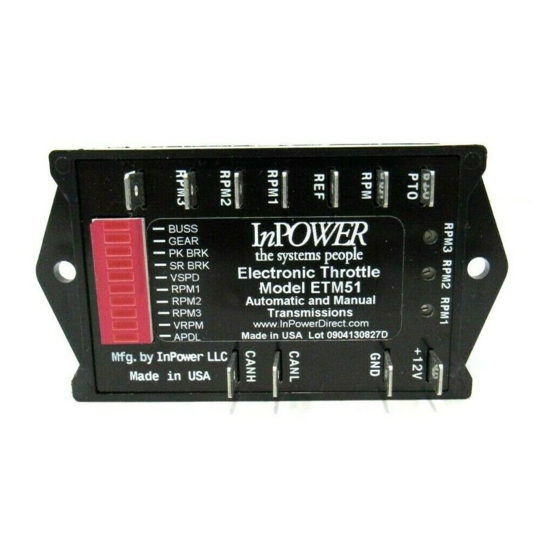
RPM1 RPM2
PTO
RPM
REF
RPM1
RPM2
RPM3
VRPM
RPM 1
Westerville, OH 43086
Tel: 740-548-0965 Fax: 740-548-2320
www.InPowerDirect.com
Document: OM-54
Date: Oct 15, 2009
© Copyright 2015 InPower LLC
8
Fused +12 Volts
On/Off
85
86
View looking into OBD-II connector
located on lower dash on driver's side
Shield
1 2 3 4 5 6 7 8
9 10 11 12 13 14 15 16
CANL (green)
RPM3
+12V
Green
(pin 14)
GND
Ground
Green
CANL
CANH
Yellow
Fused +12 Volts
Contact Us:
InPower, LLC
PO Box 2520
ETM51 Owner's Manual
Version Code: J
Date: Dec 30 2015
Introduction
Model ETM51 Electronic Throttles are designed to support 2005+ Ford trucks and
vans equipped with the Ford Stationary Elevated Idle Control (SEIC) and one of the
CANH (yellow)
following engines:
Modules come with four modes of fast idle control: Three user-adjustable preset
speeds and one variable input based on a remote variable resistor. The ETM51
installation requires customer-supplied control wiring to select the required mode of
operation and to connect to the Ford SEIC wiring. Ford provides blunt-cut wires, and
Shield
these may be connected to the ETM51 module via 0.25 inch Faston blade terminals.
(pin 5)
Yellow
The ETM51 kit includes a three foot data cable with a 16-pin connector plug for the
(pin 6)
OBDII data link connector (DLC) on one end and two faston terminals at the other.
The DLC is usually located at the lower part of the dash on the driver's side.
Operation
When the vehicle is parked and Chassis Ready Conditions are satisfi ed, the engine
idle speed may be controlled by selection of one of the four available modes: three
presets and one variable RPM. The preset RPM modes may be adjusted via three
calibration potentiometers on the top of the ETM51 unit.
Chassis Ready Conditions
1.
2.
3.
4.
5.
6.
7.
8.
© Copyright 2015 InPower LLC
1
OWNERS MANUAL
Model ETM51
Electronic Throttle Module
for
2005+ Ford Gas & Diesel Engines
ord Gas & Diesel
6.4 Liter Power Stroke Diesel
6.0 Liter Power Stroke Diesel
6.7 Liter Power Stroke Diesel
Parking brake is set
Gear shift lever is in PARK (automatic only) or NEUTRAL (F750)
Foot is off the service brake
Foot is off accelerator pedal
Vehicle is stationary
Engine is started and idling below 900 RPM
Coolant temperature >140°F (Gas), 120°F (Diesel)
Transmission temperature 20°F to 240°F
ETM51 Owner's Manual
Document: OM-54
Date: Oct 15, 2009
6.8 Liter Triton Gas
5.4 Liter Triton Gas
6.2 Liter Triton Gas
Version Code: J
Date: Dec 31, 2015
Advertisement

Related Manuals for InPOWER ETM51


Summary of Contents for InPOWER ETM51
- Page 1 (pin 14) (pin 5) Ground Yellow The ETM51 kit includes a three foot data cable with a 16-pin connector plug for the (pin 6) Green CANL OBDII data link connector (DLC) on one end and two faston terminals at the other.
- Page 2 Instead, the Ford SEIC must be manually reset by Green Shield turning the Fast Idle switch off and then back on. With ETM51 revision H and later (pin 14) (pin 5) software, the rest can be accomplished automatically on gas engine systems with...
- Page 3 RPM 2 This could be caused by a chassis ready condition issue or some other PCM system problem. This could also be caused by the failure to power the ETM51’s +12V input until after the engine is started RPM 3...
- Page 4 RPM2 and RPM3) and adjust the three respective ten turn potentiometers on Mount the ETM51 Module under the dash or on a fl at surface using the two mounting the ETM51 to the desired RPM. (900 to 2250 RPM on gas engines and 1200 to holes.
Need help?
Do you have a question about the ETM51 and is the answer not in the manual?
Questions and answers