Advertisement
Quick Links
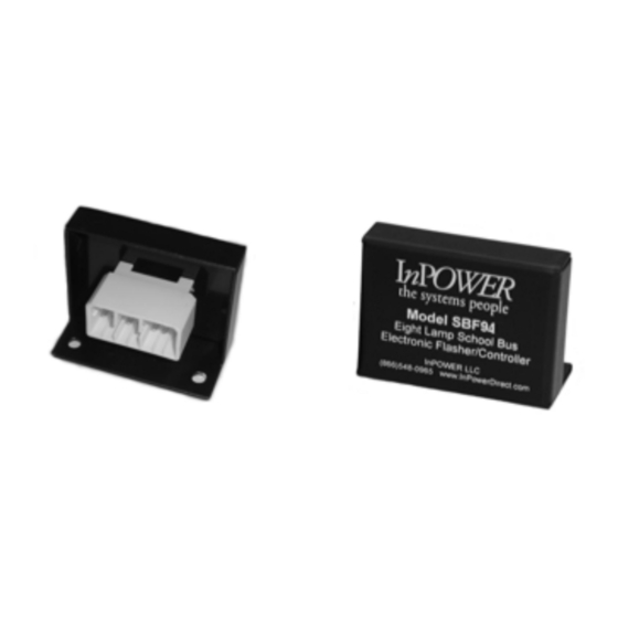
OWNERS MANUAL
Model SBF94
Eight Lamp School Bus
Electronic Flasher/Controller
Introduction
The Model SBF94 flasher/controller is a completely electronic micro-processor
based device dedicated to the school bus warning light application. Its +12 volt
outputs operate the stop arm, stop arm lights, and eight 80 watt warning
lamps. Inputs to unit include Master Switch, Override Switch, Start Switch and
Service Door Switch. Its industry standard functionality can accommodate
both sequential and non-sequential modes of operation.
The design provides safeguards for over current, over temperature, short
circuit, and loss of ground. A highly efficient current switching circuit is
employed that produces very little heat loss. Advanced electronic circuitry
employs surface mount technology (SMT). Its metal case is made of rugged
anodized aluminum.
The SBF94 utilizes the Tyco/Amp Multilock Series 070 connector system. The
12-pin header (containing male pins) is integral to the flasher case. The 12-pin
connector plug (not supplied with the flasher) uses female pins.
Installation
The SBF94 should be located in a dry area such as the electrical compart-
ment of the school bus. It should be accessible to the lamp wiring, 12 volt
power and ground. Mount the flasher on a clean, smooth metal surface to
ensure the most effective heat transfer (the mounting plate removes heat from
the flasher).
Before wiring the flasher/controller, disconnect the 12 volt power from
the chassis by removing the battery connection.
Wire the flasher/controller to the required lights, ground, power and other
devices as shown in the Wiring Diagrams and Technical Description sections.
Ensure that the power wiring to the flasher/controller is fused. The fuse and
wire size must be of sufficient size to protect the wiring and prevent from false
tripping due to the lamp loads and high inrush currents. It is very important to
provide a good ground to the unit. The wiring harness connecting to the flasher
should be properly secured to prevent damage from vibration and stress on the
connections.
Advertisement

Related Manuals for InPOWER SBF94


Summary of Contents for InPOWER SBF94
- Page 1 (not supplied with the flasher) uses female pins. Installation The SBF94 should be located in a dry area such as the electrical compart- ment of the school bus. It should be accessible to the lamp wiring, 12 volt power and ground.
- Page 2 Master Switch Master Sw Fuse +12 V Master Sw Right Amber Right Amber Right Red Right Red Stop Stop Arm SBF94 Left Red Left Red Left Amber Left Amber Start Switch Start Switch +12V +12Volts Door Switch Flash Red Only...
- Page 3 Override Sw Master Sw Master Switch Fuse Master Sw +12 V Right Front Right Amber Right Rear Right Red Stop SBF94 Stop Arm Left Front Left Red Left Rear Left Amber Start Switch Start Switch +12V +12Volts Door Switch Flash Red Only...
- Page 4 75 flashes per minute at a 50% duty cycle. Warranty InPOWER LLC warrants its products to be free from defects in material and workmanship under normal use, care and maintenance for a period of two (2) years from the date of shipment.
Need help?
Do you have a question about the SBF94 and is the answer not in the manual?
Questions and answers