Table of Contents
Advertisement
Quick Links
Instructions Manual
MIF-2000/11-I [01-2019]
Original manual
This manual contains important instructions and warnings.
You must read them before mounting, making the electrical
connections and starting up. You must also comply with the
instructions for the components related to this pump.
Please remember that this Manual must be kept close to the
motor pump group.
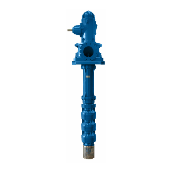
BEV/BEV-LO
Deep Well Vertical Pumps
Main Engine Lubricating Oil Pump
Advertisement
Table of Contents

Subscribe to Our Youtube Channel
Related Manuals for KSB BEV


Summary of Contents for KSB BEV
- Page 1 BEV/BEV-LO Instructions Manual MIF-2000/11-I [01-2019] Deep Well Vertical Pumps Main Engine Lubricating Oil Pump Original manual This manual contains important instructions and warnings. You must read them before mounting, making the electrical connections and starting up. You must also comply with the instructions for the components related to this pump.
-
Page 2: Table Of Contents
Right angle gear drive (for engine driven AME PLATE 4.7 F .. 8 pumps) 31 ORCES AND MOMENTS PERMITTED IN THE NOZZLES 9.1.7 BEV-LO sectional ........32 5 INSTALLATION............. 9 5.1 C ........9 HECK BEFORE ASSEMBLY 5.2 G ..........9 ROUP POSITIONING 5.2.1... -
Page 3: General Items
BEV/BEV-LO General Items Personnel qualifications and instruction All Service, Maintenance, Inspection and Assembly personnel This KSB pump has been developed in line Note must be duly qualified. The terms regarding responsibility, with current technical levels, manufactured competence and supervision of personnel must be regulated with great care and put through stringent Quality Control. -
Page 4: Safety Instructions For Maintenance
Before dismantling the pump, if the liquid is toxic or safety. The use of other parts invalidates any liability of KSB dangerous, it must be decontaminated. For this purpose for consequential damage. -
Page 5: Transport And Storage
BEV/BEV-LO KSB pumps marked with the ATEX plate are valid for Remember that the equipment must never be lifted group II category 2 and 3, zones 1, 21, 2 and 22 using the eyebolts or lifting lugs of each element temperature class as shown on the plate and Conformity (e.g. -
Page 6: Provisional Storage
Inspect the protective coating or painted surfaces. If any deficiency is to be seen, proceed to repair it. If • Hydraulic efficiency (%) with a trimmed impeller: see repainting needed consult KSB for the characteristics datasheet of the paint. • Pump performance curves, efficiency curves included: •... -
Page 7: Denomination
Flow rate in m Customer item Internal pump reference (optional) Head in metros Viscosity (N/A) Number of stages BEV- L O 1 2 5 / 2 – 1 0 . 1. 2 Series: BEV-LO Component size Number of stages Hidraulic code 10: Type... -
Page 8: Forces And Moments Permitted In The Nozzles
BEV/BEV-LO Forces and moments permitted in the nozzles MAXIMUM STRAINS PERMITTED IN CASE OF DISCHARGE HEAD IN CAST IRON OR BRONZE (1) FORCES [N] MOMENTS [N.m] DN FLANGE DISCHARGE DISCHARGE HEAD SIZE 80 - 3” 3/10 100 - 4” 4/10 1010 125 - 5”... -
Page 9: Installation
300 mm and the liquid level must other parties. KSB only offers details and comments as a help, not drop below the minimum submergence level (S) shown in but does not assume any responsibility with regards to the the following chart. -
Page 10: Equipment Installation
BEV/BEV-LO 5.2.2 Equipment installation Join the column shafts and pump using the corresponding In order to prevent misalignment between the axes, it sleeve or coupling. It is important that the ends of both shafts is necessary to correctly install, check and maintain are tight and that the joint is in the centre of the sleeve, thus the coupling. - Page 11 BEV/BEV-LO Couple the column shaft, bring down the head and join the flanges. Adjustment of impellers So far we have all these joint shafts forming a compact piece of equipment, as if it were a single shaft, which protrudes through the top of the coupling. At this moment each impeller stops against its cell in the lower part.
-
Page 12: Pipe Joint
B desirable [mm] 10E-40H/2B EXAMPLE: In a BEV-1226/6 pump, for 200 m3/h at 90 wcm., with 20 column sections of 8” x 1 ½” x 3 m (total 60 metres), In all the cases where the pump has packing, the distance the adjustment height will be: between the coupling heads must be between 2 and 4 mm. -
Page 13: Electrical Connection
BEV/BEV-LO The pipes must be anchored immediately before and after the through constant control of the seal tightness of the auxiliary pump, coupling to it without any tension. pipe joints by the plant operator. Auxiliary pipes are designed exclusively to support internal... -
Page 14: Non Electric Motors
Rotation direction. Check section 7.2.2. Check the motor rotation direction by starting Note BEV-LO bearings are lubricated by the pumping fluid. up and immediately shutting down. rotation direction must correspond with that shown by the FRICTION BEARING BUSHES: pump arrow located on the pump casing or support. If the... -
Page 15: Service Limits
BEV/BEV-LO Operation is as follows: The pump must NEVER work with zero flow or flow which is less than the operating minimum, as internal Fill the water tank for the first time. recirculation will cause the fluid to heat up quickly, leading to hazards (including explosion) as a result of the high Open the ¾”... -
Page 16: Temperature Of The Liquid To Be Pumped
5.2.2 of this manual. the order and in the ATEX conformity declaration. If Maintenance/inspection the pump is to work at a higher temperature, please ask KSB. 7.2.1 Checking instructions 6.2.3 Density of the liquid to be pumped... - Page 17 BEV/BEV-LO Lubricated with pumping fluid: If the pumped fluid is clean Release the support upper cap (without particles in suspension) and non-aggressive, the Pour oil through this orifice until the level is between the friction bearings are lubricated with the pumped fluid.
-
Page 18: Emptying/Drainage
BEV/BEV-LO Oil change Dismounting 7.4.1 Fundamental instructions/observations The oil should be changed every 1500 hours of operation, at least once a year. dusty, humid aggressive Before dismounting, ensure the pump cannot Note environments, or if the operation temperature exceeds 82ºC, be started up. -
Page 19: Assembly
The cuts, seen from above, may be straight or inclined at bearing bush. 45º. (see figure) Pumps type BEV-LO We recommend leaving a small clearance of 0.5 mm in To disassemble this type of pumps, follow the instructions the packing cut. -
Page 20: Pump
59.9 especially impellers and casings. The pump materials have been selected in accordance with the process fluid indicated in the datasheets. If this fluid is modified, check with KSB that the new fluid is suitable for the 1050 pump. 1420... -
Page 21: Recommended Spare Parts
BEV/BEV-LO Recommended spare parts BEV: Reference Recommended spare parts for (1) Part denomination Start-up 2 years 5 years Joints (set) Packing Mechanical seal Bearing (set) Wear ring Deflector protection Impeller nut Circlip (set) Keys (set) Pump shaft Intermediate drive shaft (set) -
Page 22: Preventative Maintenance
BEV/BEV-LO Preventative maintenance DESCRIPTION OF THE OPERATION Nº PROCEDURE REGULARITY CONSEQUENCE TO BE CARRIED OUT Check for packing leaks Visual inspection Weekly Check for oil leaks Visual inspection Weekly 11.16 Check for leaks between flanges Visual inspection Monthly Check for grease or oil leaks... -
Page 23: Operation Anomalies
Lack of rigidity in the foundations or anchor bolts loose Make new foundations or tighten the bolts Pump with cavitation or incoming air. Improve the suction. Consult KSB. Insufficient pipe diameters Larger diameter pipes, whenever possible Twisted well Correct it... -
Page 24: Annexes
BEV/BEV-LO Annexes Sectional plans Electric motor driven pump (1) Coupling system (for electric motor) Discharge head Column pipe Pump Strainer and foot valve This assembly is merely informative. It does not necessarily reflect the specifications of the pump you have... - Page 25 BEV/BEV-LO Engine driven pump (1) Right angle gear drive (for engine) Discharge head Column pipe Pump Strainer and foot valve (1) This assembly is merely informative. It does not necessarily reflect the specifications of the pump you have purchased.
-
Page 26: Pump
BEV/BEV-LO 9.1.1 Pump PUMPS PUMPS PUMPS SIZE SIZE SIZE 8000 6056 1063, 1066 8050, 8056 1226, 1280, 1286 1486 6685 PUMP SIZE 271.1 545.1 920.1 920.2 550.1 550.2 560.1 560.2 271.2 545.2 Ref. Denomination Ref. Denomination 106 Suction casing 546 Conical sleeve... -
Page 27: Filter And Foot Valve
BEV/BEV-LO 9.1.2 Filter and foot valve Ref. Denomination Suction filter Friction bearing bush Valve body Valve seat Valve shutter Valve pin Setscrew 9.1.3 Column pipe Ø shaft ≤ 1” 1” < Ø shaft ≤ 1.15/16” 1.15/16” < Ø shaft 901.1 940.1... -
Page 28: Discharge Head
BEV/BEV-LO 9.1.4 Discharge head 903.1 901.1 903.2 901.2 Ref. Denomination Discharge head Drive shaft O-ring Circular gasket Packing box Packing gland Packing Friction bearing bush Priming pipe Cooling pipe Adapter piece Racord Threaded coupling Hexagonal head screw Bolt Plug Setscrew... -
Page 29: Coupling System (For Electric Motor Driven Pumps)
BEV/BEV-LO 9.1.5 Coupling system (for electric motor driven pumps) Coupling 10E-10L/2 Coupling 10E - 40H/2 Coupling 16 ½ - 125H/2... - Page 30 BEV/BEV-LO Coupling AE - 400 920.1 554.1 Ref. Denomination 165 Cooling chamber cover 904.1 861.1 320 Bearing 940.1 420.1 861.2 330 Support 904.2 341 Pedestal 901.2 320.1 940.2 360 Bearing cover 901.1 382 Bearing support 320.2 400 Gasket 412.1 412 O-ring 554.2...
-
Page 31: Right Angle Gear Drive (For Engine Driven Pumps)
BEV/BEV-LO 9.1.6 Right angle gear drive (for engine driven pumps) Ref Denomination Ref Denomination 164 Inspection cover 646 Oil retaining sleeve 212 Intermediate drive shaft 662 Coil 213 Drive shaft 683 Cap 300 Support 707 Lubrication pipe 320 Bearing 861 Half coupling... -
Page 32: Bev-Lo Sectional
BEV/BEV-LO 9.1.7 BEV-LO sectional... - Page 33 BEV/BEV-LO Ref. Denominación Ref. Denominación 106 Suction casing 525 Spacer sleeve 108 Stage casing 529 Bearing bush 115 Discharge casing 550 Washer 160 Cover 554 Flat washer 171 Diffuser 561 Grooved pin 210 Shaft 712 Intermediate pipe 230 Impeller 800 Motor...
- Page 34 BEV/BEV-LO This page has been left blank on purpose.
- Page 35 BEV/BEV-LO Certificate of Decontamination … … … … … … … … … … … … … … … … … … … … … … … .. Type Order number/ Order item number *) … … … … … … … … … … … … … … … … … … … … … … … ..
- Page 36 KSB shall in no case be liable for any direct or indirect damage which the Product may suffer as a result of defective installation, incorrect storage, lack of maintenance, negligent handling, handling by unauthorised personnel, overloading or deficient functions, or for any damages resulting from external influences such as chemical, electrochemical and electrical agents.
Need help?
Do you have a question about the BEV and is the answer not in the manual?
Questions and answers