
Subscribe to Our Youtube Channel
Related Manuals for Stealth Desinger+ SC-09FM-HP230


Summary of Contents for Stealth Desinger+ SC-09FM-HP230
- Page 1 UNIVERSAL FLOOR/CEILING OWNER’S MANUAL Models: SC-09FM-HP230 SC-12FM-HP230 SC-18FM-HP230 SC-24FM-HP230...
-
Page 2: Table Of Contents
Thank you for choosing a S t e a l t h Floor/Ceiling Air Conditioning & Heating System! Please read this owner’s manual carefully before operation and retain it for future reference. Table of Contents Safety Precautions ........3 System Parts . -
Page 3: Safety Precautions
SAFETY PRECAUTIONS Please read the following before operation. Recognize safety information. This is the safety-alert symbol. When you see this symbol on the unit and in instructions or manuals, be alert to the potential for personal injury. Understand these signal words: DANGER, WARNING, and CAUTION. These words are used with the safety-alert symbol. -
Page 4: System Parts
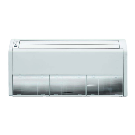
SYSTEM PARTS Air Outlet Indoor Unit Air inlet Power Supply Part Name 1. Front Cabinet 2. Air Inlet 3. Wired Controller (Optional) 4. Remote Controller 5. Drain Pipe 6. Gas Pipe 7. Liquid Pipe 8. Service Cover 9. Front Panel Air inlet Outdoor Unit Air outlet... -
Page 5: System Functions
(Low, Medium or High) to achieve maximum comfort. INTELLIGENT PRE-HEATING Stealth systems guard against the annoying cool air blown into the room in heating mode. The system constantly monitors the discharge air temperature. It will delay the indoor fan until the indoor coil has warmed up to prevent blowing uncomfortable cool air into the room. - Page 6 SYSTEM FUNCTIONS SWING LOUVER The adjustable swing louvers can be controlled from the wireless controller. Swing louvers allow nine different air discharge directions including Continuous Sweep. Maximize comfort by adjusting the direction of airflow in the room by moving the louvers up or down. POWER FAILURE MODE Power interruptions are no problem for the Multi21 system.
- Page 7 SYSTEM FUNCTIONS X-FAN MODE When operating in humid areas, the X-fan or Dry Coil function allows the indoor fan to run for a pre-determined amount of time after the unit is turned off (cooling or dry modes) to ensure that additional moisture is removed from coil. FAHRENHEIT °F / CELSIUS °C The remote controller can be set to display in either °F or °C.
- Page 8 OPERATION OF WIRELESS REMOTE CONTROLLER Remote Controller Part Name 1. ON/OFF Button 2. Down Button 3. Up Button 4. Fan Button 5. Mode Button 6. I Feel Button 7. Air Function 8. Clock Button 9. Timer On Button 10. Swing Louver Button 11.
- Page 9 OPERATION OF WIRELESS REMOTE CONTROLLER REMOTE CONTROLLER OPERATIONS The wireless remote controller is sleek, versatile and allows you to change room temperatures and functions on your Multi21 Floor/Ceiling system from the palm of your hand. The large LCD display and buttons make it easy-to-understand and easy-to-use. The remote controller is set from factory to display temperatures in °F.
- Page 10 OPERATION OF WIRELESS REMOTE CONTROLLER MODE BUTTON : AUTO Use the “MODE” button to select one of the available modes. : COOL The selected mode will be displayed on the remote controller and : DRY the appropriate light will illuminate on the front display panel. : FAN ONLY AUTO –...
- Page 11 OPERATION OF WIRELESS REMOTE CONTROLLER TIMER SETTING Timer-ON / Timer-OFF BUTTON To set when you want the unit to turn On at the end of a selected time period, use the button labeled “Timer-ON /Timer-OFF”on the remote controller. Press this button to make the clock icon disappear, replaced with the word “ON”...
- Page 12 OPERATION OF WIRELESS REMOTE CONTROLLER DISPLAYING SETPOINT, INDOOR OR OUTDOOR TEMPERATURE ON FRONT PANEL: The setpoint temperature, outdoor temperature or room temperature can be displayed on the front panel. Only setpoint temperature is displayed on the remote controller. When the “TEMP” button is pushed once, the temperature indicator is displayed.
- Page 13 OPERATION OF WIRELESS REMOTE CONTROLLER CLOCK SETTING Press this button to set clock time.“ ” icon on remote controller will blink. Within 5 seconds, press" + " and " - " button to set clock time. With each pressing of " + " and " - " buttons, clock time will increase or decrease 1 minute.
- Page 14 OPERATION OF WIRELESS REMOTE CONTROLLER PRIVACY LOCK The Privacy Lock prevents unauthorized access to the unit controls and prevents tampering with system settings. The remote controller can be locked by pushing the" + " and " - " buttons simultaneously. The Privacy Lock icon will be displayed on the remote controller.
-
Page 15: Wired Tether Controller
OPERATION OF WIRED TETHER CONTROLLER ON/OFF BUTTON Press On/Off to turn On the unit. Press again to turn it Off. “Off” State “On” State MODE SETTING When the unit is ON, press Mode button to select an operating mode. It will change sequentially as shown below: Auto–Cool–Dry–Fan–Heat Cool Heat... - Page 16 OPERATION OF WIRED TETHER CONTROLLER FAN SETTING When the unit is ON, press Fan button to select the fan speed of the indoor unit. It will change sequentially as shown below. Medium High TURBO MODE Turbo mode will force the unit up to maximum capacity to heat or cool the room in the shortest amount of time.
- Page 17 OPERATION OF WIRED TETHER CONTROLLER TIMER SETTING The Multi21 System has two timer modes. The Timer-On mode will turn the unit ON after the preset time period. The Timer-Off Mode will turn the unit OFF after the preset time period. The preset time period can be from 0.5 to 24 hours in 0.5 hour increments.
- Page 18 OPERATION OF WIRED TETHER CONTROLLER Timer-Off Setting Set the time period for the unit to remain ON before turning OFF by pressing the ▲ or ▼ Turn the unit On, press the Timer button. The ON icon will flash and the hours will be displayed. buttons.
- Page 19 OPERATION OF WIRED TETHER CONTROLLER SLEEP MODE The unit will automatically adjust room temperature during your sleep time. This slight change in temperature will not affect your comfort level due to the natural effects that sleeping has on the body, but it will save on energy consumption and will lower your electric bill. Press the SLEEP button to select Sleep Mode.
- Page 20 OPERATION OF WIRED TETHER CONTROLLER CELSIUS OR FAHRENHEIT TEMPERATURE DISPLAY The wired Tether Controller is set from the factory to display ▼ temperature in Fahrenheit ( Fº). If Celsius (Cº) is desired, turn the unit OFF, press Mode and buttons at the same time for 5 seconds to alternate between temperature displays.
- Page 21 OPERATION OF WIRED TETHER CONTROLLER I-FEEL MODE The indoor unit will sense room temperature at the wired Tether Controller instead of at Indoor Unit Room Sensor A the return air section of the indoor unit. Tether Controller Indoor Room Sensor B I-Feel Settings Press the Function button until the I-Feel icon is displayed, then press Enter/Cancel to activate the function.
-
Page 22: Care And Cleaning
CARE AND CLEANING Routine maintenance consists of checking the condensate drain for clogs, hosing off the outdoor coil of outdoor unit and cleaning the air filter and the indoor cabinet. W RNING Turn off power and disconnect from indoor and outdoor units before cleaning. Failure to do so could cause electric shock. -
Page 23: Troubleshooting
TROUBLESHOOTING PROBLEM CAUSE/SOLUTION System does not restart. Cause: The system has a built-in three-minute delay to prevent short and/or rapid cycling of the compressor. Solution: Wait three minutes for the protection delay to expire. Indoor unit emits unpleasant odor Cause: Typically unpleasant odors are the result of mold or mildew forming on when started the coil surfaces or the air filter. - Page 24 TROUBLESHOOTING PROBLEM CAUSE/SOLUTION Water leaking from the indoor Cause: While it is normal for the system to generate condensate water in unit into the room. cooling mode, it is designed to drain this water via a condensate drain system to a safe location. Solution: If water is leaking into the room, it may indicate one of the following.
-
Page 25: Diagnostic Codes
DIAGNOSTIC CODES Troubleshooting The unit has onboard diagnostics. The outdoor unit will provide status indicators. The indoor wall unit and remote controller will display error codes. The following is a summary of the codes with explanation: Indoor Unit Outdoor Unit Indicators Malfunction Name Possible Causes &... - Page 26 DIAGNOSTIC CODES Outdoor Unit Indicators Indoor Unit Malfunction Name Possible Causes Display Yellow High Temperature 1) Incorrect refrigerant charge level 6 flashes Resistant Protection and 1 sec Off 2) Refrigerant metering device malfunction 3) Compressor malfunction Cold Air Protection 1) Indoor coil has not reach minimum heating temperature 2) Indoor ambient is abnormally cold 3) Indoor control board malfunction EEPROM Memory Malfunction...
- Page 27 DIAGNOSTIC CODES Outdoor Unit Indicators Indoor Unit Malfunction Name Possible Causes Display Yellow High Compressor Discharge 2 flashes and 4 flashes 1) Cooling load is too great Temperature - Frequency 1 sec Off and 1 sec Off 2) Outdoor ambient temperature too high Decrease/Limit Mode 3) Refrigerant charge too low 4) Metering device malfunction...
- Page 28 DIAGNOSTIC CODES Outdoor Unit Indicators Indoor Unit Malfunction Name Possible Causes Display Yellow Incompatible Indoor and 16 flashes Indoor and outdoor units are not compatible Outdoor Units and 1 sec Off Compressor Phase Current 1) IPM module malfunction Protection 2) Outdoor control board malfunction 3) Compressor malfunction Module Temperature Sensor Outdoor control board malfunction...
-
Page 29: Energy Saving Tips
ENERGY SAVING TIPS 1. Relaxing room temperature at night is OK: During the nighttime hours you don't require the same level of conscious cooling or heating. Try using Sleep Mode to gradually relax room temperature and allow the unit to run less and save energy. 2. - Page 30 Phone No. / E-mail STEALTH (1HVAC Energy LLC) warrants this product against failure due to defect in materials or workmanship under normal use and maintenance as follows. All warranty periods begin on the date of original installation. If the date cannot be verified, the warranty period begins one hundred twenty (120) days from date of manufacture.
Need help?
Do you have a question about the Desinger+ SC-09FM-HP230 and is the answer not in the manual?
Questions and answers