Table of Contents
Advertisement
Quick Links
Installation & Owner's Manual
Original Instructions
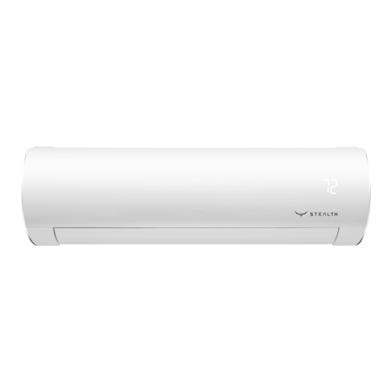
Mini Split Air Conditi oner
Thank you for choosing our product.
Please read this Installation and the
Owner's Manual carefully before
installing and operating and retain it for
future reference.
SC-30WPL-HP230 SC-30ZPL-HP230
SC-36WPL-HP230 SC-36ZPL-HP230
Advertisement
Table of Contents

Subscribe to Our Youtube Channel
Related Manuals for Stealth PINNACLE SC-30WPL-HP230


Summary of Contents for Stealth PINNACLE SC-30WPL-HP230
- Page 1 Installation & Owner's Manual Original Instructions Mini Split Air Conditi oner SC-30WPL-HP230 SC-30ZPL-HP230 SC-36WPL-HP230 SC-36ZPL-HP230 Thank you for choosing our product. Please read this Installation and the Owner’s Manual carefully before installing and operating and retain it for future reference.
-
Page 2: Table Of Contents
Content Operation Notices Precautions......................1 Parts name ......................6 Screen Operation Guide Operation of wireless remote controller..............7 Introduction for icons on display screen..............7 Operation of wireless remote controller..............8 Emergency operation ..................16 Maintenance Clean and maintenance..................16 Malfunction Malfunction analysis .................... - Page 3 Explanation of Symbols Indicates a hazardous situation that, if not avoided, will DANGER result in death or serious injury. Indicates a hazardous situation that, if not avoided, could WARNING result in death or serious injury. Indicates a hazardous situation that, if not avoided, may CAUTION result in minor or moderate injury.
-
Page 4: Precautions
Precautions WARNING Maintenance must be performed by qualified professionals. Otherwise, it may cause personal injury or damage. Do not repair air conditioner by yourself. It may cause electric shock or damage. Please contact a licensed HVAC contractor whenever repair is needed. To prevent possible personal injury or damage, keep fingers and objects clear of air inlet or outlet. - Page 5 Precautions WARNING Attachment Installation must be performed by licensed, qualified professionals. Follow all electric safety regulations and codes when installing the unit. According to the local code, use qualified power supply circuit wiring and circuit breakers. Install circuit breakers to protect you and your equipment. An all-pole disconnectswitch having a contact separation of at least 3mm in all poles should be used.
- Page 6 Precautions WARNING Do not turn on the power before finishing installation. If the supply cord is damaged, it must be replaced by the manufacturer or qualified licensed professionals in order to avoid a hazard. The temperature of refrigerant circuit will be high, please keep the interconnecting wire away from the copper tubing.
- Page 7 Precautions WARNING All wiring terminal strips and connection boxes must be easily accessible for installation and service. For the air conditioner without plug, an circuit breaker must be installed and easily accessible. To avoid personal injury or damage, if you need to relocate the air conditioner, only a qualified licensed technician should perform the work.
-
Page 8: Parts Name
Parts name Indoor Unit air inlet panel aux.button horizontal louver air outlet temp. indicator heating indicator display cooling indicator receiver power window indicator drying indicator (Display content or position may be different from above graphics, please refer to actual products) remote control Outdoor Unit air inlet... -
Page 18: Emergency Operation
Emergency operation If remote controller is lost or damaged, please use auxiliary button to turn on or turn off the air conditioner. The operation in details are as below: air conditioner. When the air conditioner is turned on, it will operate under auto mode. - Page 19 Clean and maintenance Open panel Pull out the panel to a certain ● Use dust catcher or water to the water (below 45℃ (113°F)) to clean it, and then put it in a shady and cool place to dry. panel cover tightly. WARNING operation environment, clean frequency can be increased.
- Page 20 Clean and maintenance NOTICE: Checking before use-season 1. Check whether air inlets and air outlets are blocked. 2. Check whether circuit break, plug and socket are in good condition. 4. Check whether mounting bracket for outdoor unit is damaged or corroded. If yes, please contact dealer.
-
Page 21: Malfunction Analysis
Malfunction analysis General phenomenon analysis Please check below items before asking for maintenance. If the malfunction still Phenomenon Check items Solution ● Whether it's interfered severely ● Pull out the plug. Reinsert (such as static electricity, stable the plug after about 3min, and voltage)? then turn on the unit again. - Page 22 Malfunction analysis Phenomenon Check items Solution ● Power failure? ● Wait until power recovery. ● Is plug loose? ● Reinsert the plug. ● Circuit break trips off or ● Ask professional to replace fuse is burnt out? circuit break or fuse. Air condit- ●...
- Page 23 Malfunction analysis Phenomenon Check items Solution ● Whether there’s odour source, ● Eliminate the odour source. Odours are such as furniture and cigarette, emitted etc. Air conditio- ● Whether there’s interference, ● Disconnect power, put back ner operates such as thunder, wireless power, and then turn on the abnormally devices, etc.
- Page 24 Malfunction analysis Error Code ● When air conditioner status is abnormal, temperature indicator on indoor unit will ation of error code. Above indicator diagram is only Indoor for reference. Please refer to display actual product for the actual indicator and position. Error code Error code Troubleshooting...
-
Page 25: Installation Dimension Diagram
Installation dimension diagram Space to the wall At least 6 in At least 6 in Space to the wall Space to the obstruction Air inlet side ≥ 20 in Space to the wall ≥ 20 in Air outlet side Space to the wall Drainage pipe... -
Page 26: Safety Precautions For Installing And Relocating The Unit
Safety precautions for installing and relocating the unit To ensure safety, please be mindful of the following precautions. Warning When installing or relocating the unit, be sure to keep the refrigerant circuit free from air or substances other than the specified refrigerant. Any presence of air or other foreign substance in the refrigerant circuit will cause system pressure rise or compressor rupture, resulting in injury. -
Page 27: Tools For Installation
Tools for installation 1 Level meter 2 Screw driver 3 Impact drill 4 Drill head 5 Pipe expander 6 Torque wrench 7 Open-end wrench 8 Pipe cutter 9 Leakage detector 10 Vacuum pump 11 Pressure meter 12 Universal meter 13 Inner hexagon spanner 14 Measuring tape Note: ●... -
Page 28: Requirements For Electric Connection
Requirements for electric connection Safety precaution 1. Must follow the electric safety regulations when installing the unit. circuit break. 3. Make sure the power supply matches with the requirement of air conditioner. Unstable power supply or incorrect wiring or malfunction. Please install proper power supply cables before using the air conditioner. -
Page 29: Installation Of Indoor Unit
Installation of indoor unit Step one: choosing installation location rm it with the client. Step two: install wall-mounting frame 1. Hang the wall-mounting frame on the wall; adjust it in horizontal position with the plastic expansion particles in the holes. 3. - Page 30 Installation of indoor unit Indoor outdoor Note: ● Pay attention to dust prevention and take relevant safety measures when opening the hole. ● The plastic expansion particles are Φ70 5-10 not provided and should be bought locally. Step four: outlet pipe 1.
- Page 31 Installation of indoor unit Hex nut diameter Tightening torque (N . m) open-end wrench Φ 1/4 in 15~20 Φ 3/8 in 30~40 union nut Φ 1/2 in 45~55 pipe Φ 5/8 in 60~65 torque wrench Φ 3/4 in 70~75 indoor pipe 4.
- Page 32 Installation of indoor unit 2. Make the power connection wire go cable-cross through the cable-cross hole at the back hole of indoor unit and then pull it out from the front side. power connection wire 3. Remove the wire clip; connect the power connection wire to the wiring terminal with wire clip.
- Page 33 Installation of indoor unit Step eight: bind up pipe 1. Bind up the connection pipe, power drain hose connection pipe band cord and drain hose with the band. indoor and outdoor power cord indoor unit pipe indoor power cord liquid pipe 3.
-
Page 34: Installation Of Outdoor Unit
Installation of outdoor unit (select it according to the actual installation situation) 1. Select installation location according to the house structure. 2. Fix the support of outdoor unit on the selected location with expansion screws. Note: installing the outdoor unit. ●... - Page 35 Installation of outdoor unit Step four: connect indoor and outdoor pipes 1. Remove the screw cap of valve and Tighten the union nut with torque aim the pipe joint at the bellmouth of wrench by referring to the sheet pipe. below.
- Page 36 Installation of outdoor unit 6. Fix the power connection wire and signal control wire with wire clip (only for cooling and heating unit). Note: ● Never cut the power connection wire to prolong or shorten the distance. Step six: neaten the pipes 1.
-
Page 37: Vacuum Pumping
Vacuum pumping Use vacuum pump 1. Remove the valve caps on the liquid valve and gas liquid valve manifold gauges valve and the nut of refri- gas valve gerant charging vent. refrigerant valve cap 2. Connect the charging hose charging vent of manifold to the refri- nut of refrigerant gerant charging vent of gas... -
Page 38: Check After Installation
Check after installation Items to be checked Possible malfunction The unit may drop, shake or emit noise. Have you done the refrigerant leakage test? (heating) capacity. It may cause condensation and water dripping. It may cause condensation and water Is water drained well? dripping. -
Page 39: Configuration Of Connection Pipe
Configuration of connection pipe 1. Standard length of connection pipe ● 15 ft, 25 ft, 35 ft, 50 ft. ● Min. length of connection pipe is 10 ft. 2. Max. length of connection pipe. Max length Max length Cooling Cooling of connec- of connec- capacity... - Page 40 Configuration of connection pipe Additional refrigerant charging amount for R22, R407C, R410A and R134a Diameter of connection pipe Outdoor unit throttle Liquid pipe(in) Gas pipe(in) Cooling only(oz ) Cooling and heating(0z) Φ3/8 or Φ1/2 Φ1/4 Φ1/4 or Φ3/8 Φ5/8 or Φ3/4 Φ1/2 Φ3/4 or Φ7/8 4.23...
-
Page 41: Pipe Expanding Method
Pipe expanding method Note: Improper pipe expanding is the main cause of refrigerant leakage. Please expand the pipe according to the following steps: A: Cut the pipe E: Expand the port ● Expand the port with expander. the distance of indoor unit and hard outdoor unit. - Page 42 Phone No. / E-mail STEALTH (1HVAC Energy LLC) warrants this product against failure due to defect in materials or workmanship under normal use and maintenance as follows. All warranty periods begin on the date of original installation. If the date cannot be verified, the warranty period begins one hundred twenty (120) days from date of manufacture.
Need help?
Do you have a question about the PINNACLE SC-30WPL-HP230 and is the answer not in the manual?
Questions and answers