Table of Contents
Advertisement
Quick Links
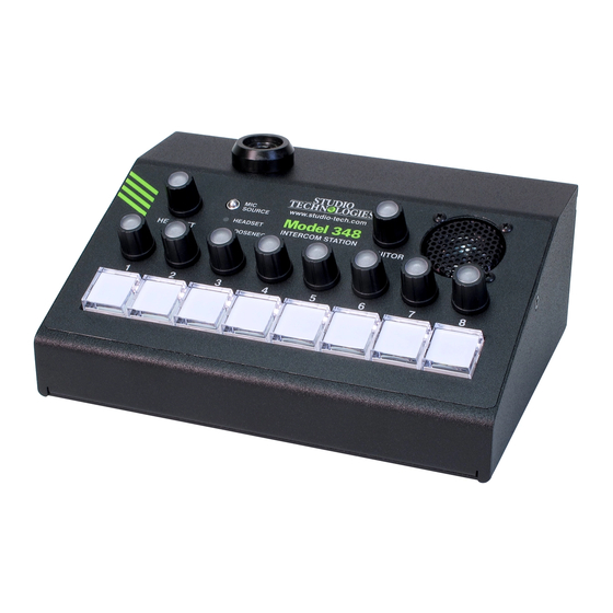
Model 348 Intercom Station
User Guide
Issue 1, January 2020
This User Guide is applicable for serial numbers
M348-00151 and later with main firmware version 1.05 and later
and STcontroller application version 2.06.00 and later.
Copyright © 2020 by Studio Technologies, Inc., all rights reserved
www.studio-tech.com
50291-0120 Issue 1
Advertisement
Table of Contents

Related Manuals for Studio Technologies 348


Summary of Contents for Studio Technologies 348
- Page 1 Issue 1, January 2020 This User Guide is applicable for serial numbers M348-00151 and later with main firmware version 1.05 and later and STcontroller application version 2.06.00 and later. Copyright © 2020 by Studio Technologies, Inc., all rights reserved www.studio-tech.com 50291-0120 Issue 1...
- Page 2 This page intentionally left blank.
-
Page 3: Table Of Contents
Table of Contents Revision History ............4 Introduction ..............5 Getting Started .............. 7 Dante Configuration ............11 Model 348 Configuration ..........12 Operation ..............19 Technical Notes ............28 Specifications ............... 33 Appendix A ..............35 Model 348 User Guide Issue 1, January 2020 Studio Technologies, Inc. -
Page 4: Revision History
MODEL 348 INTERCOM STATION Revision History Issue 1: • Initial release of complete document. Issue 1, January 2020 Model 348 User Guide Page 4 Studio Technologies, Inc. -
Page 5: Introduction
(DC powered) micro- resources makes it simple to use the Model phone. The unit provides both 5-pin female 348 locally, or as part of a REMI or “At-Home” XLR and 3.5 mm TRRS connectors which geographically diverse implementation. In allow both traditional “pro”... - Page 6 Ethernet Data and PoE input signal sources. Using RGB (red-green- blue) LEDs, each control is illuminated and The Model 348 connects to one or two local can display if signal is present on the associ- area networks (LANs) by way of two Gigabit ated audio channel or if the channel is muted.
-
Page 7: Getting Started
12 volts DC to Audio input signals arrive via 16 Dante re- power the Model 348. If this is the case then ceiver channels and pass into the Model a power supply would need to be provided 348’s 32-bit microprocessor. - Page 8 An electret gooseneck microphone that has An external source of 12 volts DC can be an integrated ¼-inch plug can be connected. connected to the Model 348 by way of the 4-pin male XLR connector which is located on One or Two Ethernet Connections the back panel.
- Page 9 4. If this condition is present it will – (low) is connected to Model 348’s mic in –/ require reversing or “flipping” the two wires in shield connection. No support is provided for a headset’s connector such that the left ear-...
- Page 10 Model 348 tions. The RTS/Telex/Bosch MCP-90-series is provides only low-voltage DC electret power. also directly compatible and will perform well.
-
Page 11: Dante Configuration
Broadway integrated circuit and, as default selection of PCM 24 would be appro- such the Model 348, is 16 so no limitation can priate. Clocking and Device Latency can be adjusted if required but the default values are exist. -
Page 12: Model 348 Configuration
INTERCOM STATION If Switched is selected (the factory default) manually set to a fixed (static) configuration. then the Model 348 will be able to establish While this is a more-involved process than one connection with an Ethernet network. simply letting DHCP or link-local “do their thing,”... - Page 13 • Button Mode local area network (LAN) and subnet as the • Button Function Model 348 units that are to be configured. Im- • IFB Program Dim mediately after starting STcontroller the appli- cation will locate all the Studio Technologies’...
- Page 14 Model 348’s active microphone input displayed by way of an LED, red in color, that source the gain of the microphone preampli- is located on the Model 348’s back panel below fier will operate from among five configurable the Headset A connector.
- Page 15 Monitor A or Monitor B. These buses on/off status of Dante monitor output channels contain audio content that is specified in the will not be impacted by the Model 348’s moni- individual configuration choices for the eight tor output rotary encoder. To clarify, neither audio input channels.
- Page 16 Choices are Low and High. When a talk or IFB function is active the Mod- The eight pushbutton switches, ten rotary en- el 348 will invoke a dim (attenuation) function. coders, and mic source selection function have This is designed to help achieve maximum LED indicators associated with them.
- Page 17 Upon The Model 348 is capable of generating an Model 348 power up the button will be in its audible alerting signal when a call signal is inactive state and its LEDs will not be lit.
- Page 18 20 kHz sine wave call tone perform a function. Pressing it will cause the to be sent out any Model 348 channels that button’s red LED to flash, indicating that it has are both configured for the Talk or the Talk been disabled.
-
Page 19: Operation
DC may have been connected to provide be sent only to the Monitor A output channel. power for the Model 348. A stereo or monau- Monitor B: In this mode the input audio will ral headset will typically be interfaced using be sent only to the Monitor B output channel. - Page 20 348 is not synchronized with a Dante network. coder, and pushbutton LEDs on front panel It will light solid green when the Model 348 is will light as the internal processors, Ethernet synchronized with a Dante network and an...
- Page 21 LED identification patterns will cease LED Intensity and normal Model 348 pushbutton LED, and Ethernet status LED operation will resume. On the Model 348’s front panel there are LED indicators associated with the eight channel Headset Microphone Power pushbutton switches, the mic source status Status LED display, and the ten rotary encoders.
- Page 22 LEDs will be lit whenever configuration parameter which is accessible by the function is active. Upon Model 348 power way of the STcontroller software application. If up the button’s associated function will be in switching between the two microphone sources its inactive state.
- Page 23 Note that there is no means provided 18 kHz and are active will have a 20 kHz sine within the Model 348 to adjust the level of the wave tone at a level of –20 dBFS added to IFB program input source. This should not be...
- Page 24 Using the Rotary Encoders IFB program audio input will continuously be connected to the associated Dante output On the front panel of the Model 348 there are channel. This is provided as a Program or ten rotary encoders. Eight of the rotary encod-...
- Page 25 MODEL 348 INTERCOM STATION a Model 348 is being used in an environment response to an encoder being within a group where the ambient light is very low or non- of four steps. So pushbutton 1 will light when existent. An encoder knob that’s lit dark blue...
-
Page 26: Headset Operation
Model 348’s back panel. The connectors are labeled Headset A and Headset B. Sidetone A sidetone function is available for assist-... -
Page 27: Monitor Output
These post-fader making their signal level respond resources allow a wide range of listening sce- to the setting of the Model 348’s monitor level narios to be implemented. encoder. If configured for pre-fader the level of... -
Page 28: Technical Notes
Call Indication Loudspeaker Output The Model 348 can be configured to respond The Model 348 contains a small loudspeaker to call signals that are present in any of the which is located on the right side of the front eight Dante input channels. - Page 29 An Xcelite® ler software application. In the unfortunate “greenie” screwdriver, ubiquitous to the audio event that a specific Model 348’s IP address is and broadcast industry, might be appropriate. “lost,” the Address Resolution Protocol (ARP) Once a cap is removed a custom label could networking command can be used to “probe”...
- Page 30 To observe the firmware version numbers, begin bottom front of the enclosure, and two on the by connecting the Model 348 unit to a network. back panel, must be removed (the machine Connect an external source of 12 volts DC if a screw directly above the Headset B connector PoE Ethernet connection has not been made.
- Page 31 BWY.bit for the FPGA firmware. the USB connector. The update process begins by preparing a USB 4. Apply power to the Model 348. Power can flash drive. The flash drive doesn’t have to be be provided by Power-over-Ethernet (PoE) empty (blank) but must be in the personal-com- associated with an Ethernet signal con- puter-standard FAT32 format.
- Page 32 Model 348’s default con- figuration selections to be reset to the factory values. From STcontroller select the Model 348 for which you want to restore its defaults. Select the Device tab and then select the Factory Defaults feature. Then click on the OK box.
-
Page 33: Specifications
22 Hz to 22 kHz bandwidth, 38 dB of gain Audible Alert: 3-burst sequence, 524 Hz, sine wave, Dynamic Range: >93 dB, A-weighted, 26 dB gain selectable level range Model 348 User Guide Issue 1, January 2020 Studio Technologies, Inc. Page 33... - Page 34 158 degrees F) Humidity: 0 to 95%, non-condensing Altitude: not characterized Spare Connector Location: 1 Allows a Studio Technologies’ cable assembly or op- tion module to be installed. Also compatible with Neutrik NC*D-L-1 connectors (*=3F, 3M, 5M, 6F, 6FS, etc.). Dimensions (Overall): 6.5 inches wide (16.5 cm)
-
Page 35: Appendix A
MODEL 348 INTERCOM STATION Appendix A STcontroller default Model 348 configuration values: General Menu Page: Microphone Input – Headset Mic Power: Off Microphone Input – Headset Mic Gain: 38 dB Microphone Input – Gooseneck Mic Gain: 24 dB Headset – Sidetone Level: Medium Headset –...
Need help?
Do you have a question about the 348 and is the answer not in the manual?
Questions and answers