
Summary of Contents for Baudcom BD-QAM-10G
- Page 1 IP QAM DTV Headend Processor User Manual Model:BD-QAM-10G 10G IP QAM DTV Headend Processor User Manual...
- Page 2 The contents of this document are subject to revision without notice due to continued progress in methodology, design and manufacturing. BAUDCOM shall have no liability for any error or damage of any kind resulting from the use of this document.
-
Page 3: Table Of Contents
IP QAM DTV Headend Processor User Manual Directory Chapter 1 Product Overview ......................1 1.1 Outline ............................1 1.2 Features ............................ 1 Principle Chart (Example: one 64qam card + one 48qam card) ..........2 1.4 Appearance and Description ....................3 Chapter 2 Installation Guide...................... -
Page 4: Chapter 1 Product Overview
IP QAM DTV Headend Processor User Manual Chapter 1 Product Overview 1.1 Outline BD-QAM-10G 10G IP QAM processor is an all-in-one device developed by BAUDCOM which integrates multiplexer, scrambler and modulator in one body with maximum 112 DVB-C QAM channels output. With 10G switch built in, it can process 10G optical signal to work as a traditional QAM modulator. -
Page 5: Principle Chart (Example: One 64Qam Card + One 48Qam Card)
Max PIDs Remapping 256 per output channel PID remapping (auto/manually optional) Functions PCR accurate adjusting PSI/SI table automatically generating Max simulcrypt CA Scramble Standard ETR289, ETSI 101 197, ETSI 103 197 Scrambling Connection Local/remote connection Website: http://www.baudcom.com.cn Tel: +86 21 37709251 Email:info@baudcom.com.cn... -
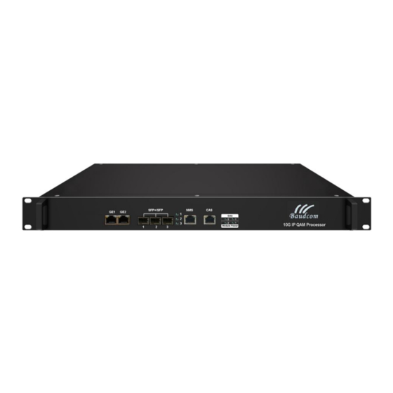
Page 6: Appearance And Description
Web-based Network management Dimension 420mm×440mm×44.5mm (WxLxH) Temperature 0~45℃(operation), -20~80℃(storage) General Power Supply AC 100V±10%, 50/60Hz; or AC 220V±10%, 50/60Hz Consumption 50W(1 daughter QAM card)/75W(2 daughter QAM cards) 1.4 Appearance and Description Panel Illustration Website: http://www.baudcom.com.cn Tel: +86 21 37709251 Email:info@baudcom.com.cn... - Page 7 NMS: network management system port CAS: Conditional Accesss System port Power Switch and supply 32/48 QAM module with RF out ports and GE ports for data input/output Fixed 64 QAM module with RF out ports Website: http://www.baudcom.com.cn Tel: +86 21 37709251 Email:info@baudcom.com.cn...
-
Page 8: Chapter 2 Installation Guide
0.8m. Electric Isolation, Dust Free Volume resistivity ground anti-static material: Machine Hall Floor 1X10 ~1X10 ,Grounding current limiting resistance: 1M (Floor bearing should be greater than 450Kg/㎡) 5~40℃(sustainable ),0~45℃(short time), Environment Website: http://www.baudcom.com.cn Tel: +86 21 37709251 Email:info@baudcom.com.cn... -
Page 9: Grounding Requirement
The area of the conduction between grounding wire and grounding strip should be no less than 25mm 2.7 Device Grounding Connecting the device’s grounding rod to frame’s grounding pole with copper wire. Website: http://www.baudcom.com.cn Tel: +86 21 37709251 Email:info@baudcom.com.cn... -
Page 10: Wire's Connection
When the device adopts united way, the grounding resistance should be smaller than 1Ω. Caution: Before connecting power cord to BD-QAM-10G DTV Headend Processor, user should set the power switch to “OFF”. 2.10 Signal and NMS Cable Connection The signal connections include the connection of input signal cable and the connection of output signal cable. -
Page 11: Chapter 3 Web Nms Management
Figure-1 3.2 Operation 3.2.1 Summary When we confirm the login, it will display the summary interface as Figure-2 where users have an over view of the system information and alarm log. Website: http://www.baudcom.com.cn Tel: +86 21 37709251 Email:info@baudcom.com.cn... - Page 12 ”, it will display the interface as Figure-3 where users can check the input Module 1 status of .There are 7 input port, including 2 GE ports and 3 SFP ports at front panel, also 2 GE ports at Module 1. Figure-3 3.2.3 Parameters Website: http://www.baudcom.com.cn Tel: +86 21 37709251 Email:info@baudcom.com.cn...
- Page 13 Operation Area Figure-4 Click “+” to add IP input, then select one channel to parse, it will display the interface where users can choose the programs to Mux out. (Figure-5) Set IP input address Website: http://www.baudcom.com.cn Tel: +86 21 37709251 Email:info@baudcom.com.cn...
- Page 14 To select all the input programs To select all the output programs To parse programs time limitation of parsing input programs General: Click “General”, it displays the interface where users can set parameters for each output channel Website: http://www.baudcom.com.cn Tel: +86 21 37709251 Email:info@baudcom.com.cn...
- Page 15 Clicking “PID pass”, it will display the interface as Figure-8 where user can add PIDs to be passed, click the “+” symbol, input current IP channel number, then input current IP source PID and output PID which is customer needed , then click “set” to apply the parameters. Website: http://www.baudcom.com.cn Tel: +86 21 37709251 Email:info@baudcom.com.cn...
- Page 16 Module 1 (32ch qam module or 48ch qam module) supports TS to output in IP format through the GE 1 & GE2 ports. Click “IP Stream”, it displays the interface as Figure-9 where to set IP out parameters. Website: http://www.baudcom.com.cn Tel: +86 21 37709251 Email:info@baudcom.com.cn...
- Page 17 RF QAM output parameters “ Channel Click config” to set each channel RF QAM output parameters Figure-10 System: Clicking “System”, it will display the interface as Figure-11 where to set network parameters. Website: http://www.baudcom.com.cn Tel: +86 21 37709251 Email:info@baudcom.com.cn...
- Page 18 3.2.4 System System → Port Control: Clicking “Port Control”, it will display the interface as Figure-12 where to set network parameters. Figure-12 System → Network: Clicking “Network”, it will display the interface as Figure-13 Website: http://www.baudcom.com.cn Tel: +86 21 37709251 Email:info@baudcom.com.cn...
- Page 19 Clicking “Account”, it will display the screen as Figure-14 where to set the login account and password for the web NMS. Figure-14 System → Configuration: Clicking “Configuration”, it will display the screen as Figure-15 where to set your configurations for the device. Website: http://www.baudcom.com.cn Tel: +86 21 37709251 Email:info@baudcom.com.cn...
- Page 20 Clicking “Firmware”, it will display the screen as Figure-16 where to update firmware for the device. Figure-16 System → Date/Time: Clicking “Date/Time”, it will display the interface as Figure-17 where users can set date/time for this device. Website: http://www.baudcom.com.cn Tel: +86 21 37709251 Email:info@baudcom.com.cn...
- Page 21 IP QAM DTV Headend Processor User Manual Figure-17 Website: http://www.baudcom.com.cn Tel: +86 21 37709251 Email:info@baudcom.com.cn...
Need help?
Do you have a question about the BD-QAM-10G and is the answer not in the manual?
Questions and answers