Table of Contents
Advertisement
Advertisement
Chapters
Table of Contents
Troubleshooting

Related Manuals for Victron energy BlueSolar SCC010005000


Summary of Contents for Victron energy BlueSolar SCC010005000
- Page 1 Manual BlueSolar Charge controller 12/24V-10A with timer...
- Page 2 EXCEED THE PURCHASE PRICE OF THE VICTRON ENERGY PRODUCTS DESCRIBED HERE IN. Victron Energy B.V. reserves the right to revise and improve its products as it sees fit. This publication describes the state of this product at the time of its publication and may...
- Page 3 Installation and Operation Manual Specification Summary Nominal system voltage: 12 / 24VDC* Maximum PV input voltage: Nominal charge / discharge current * The controller will recognize the system rated voltage when start up. If the battery voltage is lower than 18V, it will recognize the system as 12V. If the battery voltage is greater than 18V, it will recognize the system as 24V.
-
Page 4: Table Of Contents
Contents 1 Important Safety Information 2 General Information 2.1 Product Overview 2.2 Product Features 3 Installation Instructions 3.1 General Installation Notes 3.2 Mounting 3.3 Wiring 4 Operation 4.1 PWM Technology 4.2 Battery Charging Information 4.3 LED Indicators 4.4 Operation and settings 4.5 Setting the timers 5 Protections, Troubleshooting and Maintenance 5.1 Protection... -
Page 5: Important Safety Information
1. Important Safety Information This manual contains important safety, installation and operating instructions. The following symbols are used throughout this manual to indicate potentially dangerous conditions or mark important safety instructions, please take care when meeting these symbols. WARNING: Indicates a potentially dangerous condition. Use extreme caution when performing this task. -
Page 6: General Information
2. General Information 2.1 Product Overview 12/24V automatic recognition Efficient Series PWM charging, increases battery lifetime and improves solar system performance. Uses MOSFET as electronic switch, without any mechanical switch Automatic day/night recognition. Digital LED menu. ... -
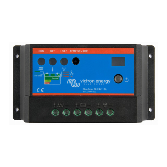
Page 7: Product Features
2.2 Product Features Figure 2-1 Features 1 –Temperature Sensor Measures ambient temperature. Used for temperature compensated charging and discharging. 2 – Charging status LED indicator A LED indicator that shows charging status and also indicates when a solar input fault condition exists 3 –... - Page 8 9 –Solar Module Terminals Connect solar modules. 10 –Battery Terminals Connect batteries. 11 –Load Terminals Connect loads.
-
Page 9: Installation Instructions
3. Installation Instructions 3.1 General Installation Notes Read through the entire installation section before beginning installation. Be very careful when working with batteries. Wear eye protection. Have fresh water available to wash and clean any contact with battery acid. ... - Page 10 WARNING: Risk of explosion! Never install the controller in a sealed enclose with batteries! Do not install in a confined area where battery gasses can accumulate. Step 1: Choose Mounting Location Locate the controller on a vertical surface protected from direct sun, high temperature, and water.
-
Page 11: Wiring
3.3 Wiring NOTE: Please follow the recommended connection order for maximum safety during installation. NOTE: The controller is a common positive ground controller. CAUTION: Don’t connect loads with surge power exceeding the ratings of the controller. CAUTION: For mobile applications, be sure to secure all wiring. Use cable clamps to prevent cables from swaying when the vehicle is in motion. - Page 12 Step 2: Load Wiring The controller loads can be connected to such electrical equipments as lights, pumps, motors and others. Fuse Load Figure 3-3 Load Wiring Connect the positive (+) and negative (-) to the controller load terminals as shown in Figure 3-3.
- Page 13 Step 3: Solar wiring WARNING: Risk of electric shock! Exercise caution when handling solar wiring. The solar module(s) high voltage output can cause severe shock or injury. Cover the solar module(s) from the sun before installing solar wiring. The controller can accept 12V or 24V nominal off-grid solar module(s). Solar Module Figure 3-4 Solar wiring Step 4: Confirm Wiring...
- Page 14 Step 5: Install Fuse Install a suitable fuse in each fuse holder in the following order: 1. Battery circuit 2. Load circuit Step 6: Confirm power on When battery power is applied and the controller starts up, the battery LED indicator will be green.
-
Page 15: Operation
4. Operation 4.1 PWM Technology (Series Pulse Width Modulation) The controller features advanced series pulse width modulation. 4.2 Battery Charging Information Figure 4-1 PWM Charging mode Bulk Charge In this stage, the battery voltage has not yet reached boost voltage and 100% of available solar power is used to charge the battery. -
Page 16: Led Indicators
Equalize Charge WARNING: Risk of explosion! Equalizing a flooded battery can produce explosive gases, good ventilation of the battery box is therefore necessary. NOTE: Equipment damage! Equalization may increase battery voltage to a level that is damaging to sensitive DC loads. - Page 17 Charging Status LED indicator Table 4-1 Color Indicator Charging Status Green On Solid Charging Green Fast Flashing Over voltage Battery status indicator GREEN ON when battery voltage in normal range GREEN SLOWLY FLASHING when battery full ORANGE ON in case of battery under voltage RED ON when the battery is over discharged Please refer to section 5 for troubleshooting.
-
Page 18: Operation And Settings
Overheating protection indicator When the heat sink of the controller exceeds 85°C, the controller will automatically cut off the input and output, and the LED display shows “H”, slowly flashing. Please refer to section 5 for troubleshooting. Overheating protection indicator Table 4-4 Color LED digital tube... -
Page 19: Setting The Timers
2. Test mode This mode is the same as Dusk to Dawn. But there is no 10 minutes delay when controller recognizes the starting voltage. The test mode makes it easy to check the system. 3. ON/OFF mode This mode is to turn ON and OFF the load manually. 4.5 Setting the timers Timer 1 Setting LED display... - Page 20 Load work mode Table 4-5 Timer 1 LED display No. Enable Dusk to Dawn, Load will be on all night Load will be on for 1 hour after ten minutes delay since sunset Load will be on for 2 hours after ten minutes delay since sunset Load will be on for 3 hours after ten minutes delay since sunset Load will be on for 4 hours after ten minutes delay since sunset Load will be on for 5 hours after ten minutes delay since sunset...
- Page 21 Load work mode Table 4-6 Timer 2 LED display No. Enable Load will be on for 1 hour before sunrise Load will be on for 2 hours before sunrise Load will be on for 3 hours before sunrise Load will be on for 4 hours before sunrise Load will be on for 5 hours before sunrise Load will be on for 6 hours before sunrise Load will be on for 7 hours before sunrise...
-
Page 22: Protections, Troubleshooting And Maintenance
5. Protection, Troubleshooting and Maintenance 5.1 Protection PV Array Short Circuit If a PV array short circuit occurs, clear it to resume normal operation. Load output overload If the load current exceeds the maximum load current rating, the controller will disconnect the load. - Page 23 5.2 Troubleshooting Trouble Shooting Table 5-1 Faults Possible reasons Troubleshooting Charging LED indicator off Check that PV and battery during daytime when PV array disconnected wire connections are sunshine falls on PV correct and tight. modules properly. Battery voltage higher Check battery voltage.
- Page 24 NOTE: If all LED’s are off. Measure battery voltage with multimeter. At least 6V is needed to start the controller. NOTE: No charging status LED indicator with normal connection. Measure the input voltage of solar module, the input voltage must be higher than battery voltage! 5.3 Maintenance The following inspections and maintenance tasks are recommended at least two times per year for best controller performance.
- Page 25 6. Technical specifications Electrical Parameters Table 7-1 Description Parameter 12 / 24VDC Nominal System Voltage With automatic system voltage recognition Battery Voltage Range 6-36V Rated Battery Current ≤0.26V Charge Circuit Voltage Drop ≤0.15V Discharge Circuit Voltage Drop ≤6mA Self-consumption Threshold Voltage Parameters Table7-2 Description Parameter...
- Page 26 Battery Voltage Parameters (temperature at 25℃) Table 7-4 Charging Parameters Battery charging setting Flooded Over Voltage Disconnect Voltage 16V; x2/24V 16V; x2/24V 16V; x2/24V Charging Limit Voltage 15.5V;x2/24V 15.5V;x2/24V 15.5V;x2/24V Equalize Charging Voltage ----- 14.6V;x2/24V 14.8V;x2/24V Boost/absorption Charging Voltage 14.2V;x2/24V 14.4V;x2/24V 14.6V;x2/24V Float Charging Voltage...
- Page 27 Environmental parameters Table 7-5 Environmental Parameter parameters Operating temperature -35℃ to +55℃ Storage temperature -35℃to +80℃ Humidity 10%-90% non condensing Enclosure IP30 Mechanical parameters Table 7-6 Mechanical Parameter Parameter 140(5.51)x65(2.56)x34(1.34) Overall dimensions mm/inches Mounting dimensions 130(5.12) x 45(1.77) mm/inches Φ4.5 Mounting hole size Terminals Net weight...
- Page 28 APPENDIX A: Dimensions mm(inches) 140(5.51) 130(5.12) Figure 1-1 Dimensions...
- Page 29 Manual IMPORTANT Always connect the batteries first. Use for 12V battery system only 12V (36 cells) solar panel array. Use for 24V battery system only 24V (72 cells) solar panel array. Use for 48V battery system only 2x24V (72 cells) solar panel array in series. BlueSolar PWM Charge Controller –...
- Page 30 IMPORTANT Always connect the batteries first. Use for 12V battery system only 12V (36 cells) solar panel array. • Use for 24V battery system only 24V (72 cells) solar panel array. • • Use for 48V battery system only 2x24V (72 cells) solar panel array in series.
- Page 31 1. Connect the battery to the charge regulator - plus and minus. 2. Connect the solar module to the regulator - plus and minus. 3. Connect the load to the charge regulator - plus and minus. The reverse order applies when deinstalling! An improper sequence order can damage the BlueSolar Charge Controller! 1.
- Page 32 4. LCD DISPLAY and SETTINGS MENU:switch between different display, or to enter/exit setting by long press. UP:press to change the settings when in setting mode. DOWN: press to change the settings when in setting mode. Load on/off button when in H mode. 4.1 Monitoring &...
- Page 33 Main display. It shows battery voltage, battery capacity, charging and discharging status. Press MENU to enter next display. Battery type setting. Change Settings Main display. press on the See table below. MENU key for several seconds until The factory setting is b01 the numbers flash, you are in: Battery type...
- Page 34 Charge current display. It shows solar to battery current and charge status. Press MENU to enter next display. Load working mode. The factory setting is 24H Press MENU to enter next display. Load working mode setting. Change Settings in the Load working mode See table below.
- Page 35 10s and measure again to make sure night falls. The factory setting is 10sec Short-circuit protection Press on the MENU setting. key again and you go Some inductive or capacitive consumer will trigger the short- circuit protection during start up. Therefore the SC- protection can be disabled manually.
- Page 36 5. Alarms High temperature Temp <85℃, controller works normally. When temp ≥ 85℃, controller will adopt first protection phase: Controller will lower the PV input current, in order to lower the controller temp; but Load works normally. There is no alarm on LCD display.
- Page 37 6. Specifications BlueSolar Charge Controller 12V/24V|30A 48V|10A 48V|20A 48V|30A Battery Voltage 12/24V Auto Select Charge & Load Current Charge mode PWM, Time and Lighting Control Automatic load disconnect Maximum solar voltage 100V Solar voltage range 15-28V 30-55V 60-100V Self-consumption <15mA Reverse polarity connection of the solar panels.
- Page 38 Manual IMPORTANT Always connect the batteries first. • Use for 12V battery system only 12V (36 cells) solar • panel array. Use for 24V battery system only 24V (72 cells) solar • panel array. BlueSolar Charge Controller 12V | 24V | 20A...
- Page 39 1. DISCRIPTION 1.1 General The BlueSolar Charger series uses Pulse Width Modulation (PWM) charge voltage control combined with a multistage charge control algorithm. This leads to superior charging and enhanced battery performance. The filtered PWM power control system uses highly efficient and reliable power MOSFET transistors.
- Page 40 2. INSTALLATION Important note: Always connect the batteries first. Connect the individual components as shown. Solar panel(s) Battery and loads in order indicated 1-6. Install the regulator near the battery. The installation environment should be indoor, dry and nonflammable. The cables should be as short as possible and have a suitable cable diameter size to minimize loss, e.g.
- Page 41 If the battery is connected with inverse polarity, the output polarity will also inverse. A 20A fuse should be inserted in the positive wire to the battery. Connect the photovoltaic module to the charge regulator. If there is sunshine, the charging indicator should turn on. Connect the load to the charge controller;...
- Page 42 Please note: The load output will cut off in case of over load or short circuit. After the first overload or short circuit the controller will resume to work automatically after 30 seconds. Please check the load and press the start push button to start when it happens again.
- Page 43 4. TO CORRECT PROBLEMS Check wires Reduce load if needed Reset controller by pressing the push button...
- Page 44 5. SPECIFICATIONS BlueSolar 12/24-20A 12V/20A 24V/20A Battery voltage 12V/24V Auto Select* Rated charge current Recommended solar panel array 36 cell 72 cell Maximum solar voltage* 1.25 times: 60 seconds Over load, short circuit protection 1.5 times: 5 seconds Self consumption SEL Sealed FLD Flooded Battery type**...
- Page 45 6. MECHANICAL DRAWING...
- Page 46 7. REMOTE METER DISPLAY [OPTION] Features LCD display: all systems parameters in digital value and symbols for system status. Battery type setting. Battery Ah setting. Temperature compensation setting. 7.1 General Two LED indicators above LCD: Green on when charging. Red on when error. The meter backlight has two backlight levels: High level for 15 seconds after pressing one of the push buttons.
- Page 47 7.2 Remote meter operation instructions Push button functions from left to right: K1: Set K2: Left K3: Right K4: ON/OFF/ESC 7.2.1 Meter display options by pressing K2 or K3 solar panel voltage, solar panel charge current battery voltage, charge current load voltage, load current battery capacity (Ah), temperature battery capacity percentage, battery temp compensation...
- Page 48 7.2.2 Data setting operation: The following parameters can be adjusted: battery capacity battery temperature compensation battery type Procedure: Use K2 or K3 to select the display option with data to be adjusted. Press K1 to enter setting mode. Press K2 or K3 to modify data. Press K1 to save the modified setting, or press K4 to return to previous setting.
- Page 49 7.3 Error Icon The red LED and the error icon will flash in case of an error. Please: Check wires Reduce load if needed Reset the controller by pressing K4 7.4 Data updating The display is updated every 10 seconds. The charged/discharged Ah and Wh counters are updated every minute.
- Page 50 8. SPECIFICATIONS Remote meter LCD specification High level backlight on: < 23mA, 15 seconds Current consumtion Low backlight on: < 20mA, 15 seconds Backlight and LED indicator off < 15mA 1.5 meters RJ45 Communication cable & port 150 gr Weight Dimensions (h x w x d) 95 x 95 x 24 mm...
- Page 51 9. MECHANICAL DRAWING...
- Page 52 Manual BlueSolar DUO Charger 12V | 24V | 20A...
- Page 53 1. DESCRIPTION 1.1 General Series pass Pulse Width Modulation (PWM) charge voltage control combined with a multistage charge control algorithm leads to superior charging and enhanced battery performance. The filtered PWM power control system uses highly efficient and reliable power MOSFET transistors.
- Page 54 2. INSTALATION Important note: Always connect the batteries first. Connect to battery #1 Connect to battery #2 Connect to 3. LED INDICATORS Remote temperature sensor A connection point for RTS (option) to remotely monitor battery temperature. Local temperature sensor Measures ambient temperature. Battery regulation is adjusted accordingly.
-
Page 55: Troubleshooting
4. TROUBLESHOOTING 1. LED blinking, short circuit, check the PV and battery, and make sure that they are in correct connection. 2. LED slowly flashing: fully charged. 3. LED ON: charging. 4. LED frequent flashing: battery connected, no charge current. 5. - Page 56 50%(pre-set) Note: In the normal charging status, the controller will divide the charging as the setting. When battery #1 is fully charged, more charge current will be go to battery #2. When the controller detects that only battery #1 is connected, all the charge current will go to the battery #1 automatically.
- Page 57 6. MECHANICAL DRAWING...
- Page 58 7. SPECIFICATIONS BlueSolar DUO 12/24-20 BlueSolar Battery Voltage 12/24V Auto Select * Rated charge current Second battery output Recommended solar panel array Maximum solar voltage Self-consumption Default settings Absorption charge (1) 14.4V 28.8V Float charge (1) 13.7V 27.4V Yes, internal sensor Battery temperature sensor Remote sensor optional Temperature compensation...
- Page 59 Manual BlueSolar PWM Charge Controller – LCD - USB 12V | 24V | 5A 12V | 24V | 10A 12V | 24V | 20A...
- Page 60 1. General Information IMPORTANT Always connect the battery first, in order to allow the Controller • to recognize system voltage Use a 12V (36 cells) solar array for a 12V system. • Use a 24V (72 cells) solar array for a 24V system. •...
- Page 61 1. Connect the battery - plus and minus. 2. Connect the solar array - plus and minus. 3. Connect the load - plus and minus. The reverse order applies when deinstalling. An improper sequence order can damage the BlueSolar PWM Charge Controller! 1.
- Page 62 4. LCD DISPLAY and SETTINGS MENU:switch between different display, or to enter/exit setting by long press. UP:press to change the settings when in setting mode. DOWN: press to change the settings when in setting mode. Load on/off button when in H mode. 4.1 Monitoring and settings Values between [ ] are for 24V battery settings Boot Display.
- Page 63 Main display: battery voltage, battery state of charge, charging and discharging status. Press MENU to enter next display. Change settings in Main display. Battery type setting. See table below. Press the MENU button for several seconds until the The factory setting is b01 display flashes, you are in: Battery...
- Page 64 PV Voltage display: PV voltage and the state of charge of the battery. Press MENU to enter next display. Charge current display: PV to battery current and the state of charge of the battery. Press MENU to enter next display. Load output settings.
- Page 65 Short-circuit protection setting. Some inductive or capacitive loads will trigger the short-circuit protection during start up. Press MENU to enter Therefore the SC-protection can be disabled the next display manually. Sc.F = OFF, Sc.n = ON. The default is ON. Discharge current display: load current and battery capacity, Press MENU to enter next display.
- Page 66 5. Alarms High temperature When temp ≥ 85℃, the controller will enter into the first protection phase: it will lower the PV input current in order to lower the temp. There is no alarm on the LCD display. When temp >90℃, the controller will enter into the second protection phase: the PV input current will be reduced to zero, the load output will be switched off and a high temp alarm icon will show on the LCD.
- Page 67 6.Specifications 12V|24V|5A 12V|24V|10A 12V|24V|20A BlueSolar PWM Charge Controller Battery Voltage 12/24V Auto Select Charge & Load Current Charge mode PWM, Time and Lighting Control Automatic load disconnect Maximum solar array voltage Solar voltage range 15-28V [30-55V] Self-consumption <10mA Reverse polarity connection of the solar panels. Reverse polarity connection of the battery.
- Page 68 Manual BlueSolar PWM-Light 48V Charge Controller (with light turn-off timer)
- Page 69 1. DESCRIPTION • Programmable load output with lighting control mode. • Three stage battery charging (bulk – absorption – float). • Protected against over current. • Protected against short circuit. • Protected against reverse polarity connection of the battery or solar array.
- Page 70 3. LED INDICATORS Green LED: Off: No sunlight or not enough sunlight. Charger off. Fast flashing: Bulk charge. On: Absorption charge. Slow flashing: Float charge. LED=Green: battery fully charged (> 48,8V) LED=Orange: battery ok (48,8V - 46V) LED=Red: battery low (44,8V) LED=Flashing Red: battery fully discharged (<...
- Page 71 4. SETTING THE LOAD OUTPUT 4.1 Settings Load output turned on during Load output permanently off 9 hours after sunset Load output turned on during Load output turned on during 1 hour after sunset 10 hours after sunset Load output turned on during Load output turned on during 2 hours after sunset 11 hours after sunset...
- Page 72 4.2 Settings description 0 Charger only The load output is switched off permanently. 1-13 Light control + delay The load output automatically turns on after sunset (array voltage < 32V) and the built-in timer starts counting. When the timer reaches the set time, or when the low voltage limit is reached, the load output will turn off.
- Page 73 5. SPECIFICATIONS BlueSolar PWM 48V Battery Voltage Rated charge current Recommended solar array 4x36 cell or 2x72 cell for 48V Automatic low voltage load disconnect Maximum solar voltage 100V Self-consumption < 10mA Shut down after 60s in case of 130% load Overload protection Shut down after 5s in case of 160% load Short circuit: immediate shut down...
- Page 74 Manual IMPORTANT • Always connect the battery first, in order to allow the Controller to recognize system voltage • Use a 12V (36 cells) solar array for a 12V system. • Use a 24V (72 cells) solar array for a 24V system. BlueSolar PWM-Pro Charge Controller 12V | 24V - 5A SCC010005010...
- Page 75 1. General Safety Information Read all instructions and cautions in the manual before starting the installation. Keep the controller away from rain exposure, severe dust, vibration, corrosive gas and intense electromagnetic interference. Do not allow water to enter the controller. There are no user serviceable parts inside the controller.
- Page 76 3. Installation and operation Important note: always connect the battery first, in order to allow the controller to recognize system voltage. The controller is a common positive controller. If system grounding is required, preferably the positive pole of the battery should be grounded.
- Page 77 Indicator Status Description: No voltage from solar Green array (night time) Low voltage from solar Green On Solid array (low irradiance) Green Slowly Flashing Charging Normal Green On Solid (Vbat > 12,1V resp. 24,2V) Green Slowly Flashing Full Green Fast Flashing Over voltage (Vbat >...
- Page 78 4. Programming the controller The default settings (see specifications) can be modified with help of software (available free of charge on our website), or with the remote panel. The panel must be connected to the controller with a standard RJ45 UTP cable.
- Page 79 5. Protection Load Overload If the load current exceeds the rated current of controller (≥1.05 times rated discharge current), the controller will disconnect the load. Overloading must be cleared, then press the switch button. Load Short Circuit Fully protected against load wiring short-circuit (≥2 times rated discharge current).
- Page 80 6. Troubleshooting Possible Faults Troubleshooting reasons Charging LED indicator off during daytime PV array Check that PV and battery wire when sunshine disconnected connections are correct and tight. falls on PV modules Battery voltage Check battery voltage. If too high, Green Battery higher than over disconnect the solar module...
-
Page 81: Technical Specifications
7. Technical specifications BlueSolar PWM-Pro charge controller 12/24V 5 A /10 A 20 A 30 A Battery voltage 12/24V Auto Select Rated charge 5 A / 10 A 20 A 30 A current Automatic load disconnect Maximum solar 28 V / 55 V (1) voltage Self-consumption 8 mA... - Page 82 8. Battery related programming options (see software manual or remote panel manual for details) Battery related programming Sealed Flooded User (default options defined setting) Battery capacity setting (needed 200Ah 1~9999 for the internal battery monitor) Over voltage load disconnect 16.0V 9~17V Charge limit 15.0V...
- Page 83 Manual Blue Solar PWM Pro setup and monitoring software...
- Page 84 Contents Region and language settings Download the software UnRAR the software Install the software Install and configure the USB driver Establishing communication Other settings Monitoring more than one controller...
-
Page 85: Region And Language Settings
“United States” resp. “English (United States) – US”. These settings can be found under “Region and Language” on the Control Panel of the computer. Download the software Download the software to your PC from the Victron Energy site. UnRAR the software Use WinZip or RarZilla Free Unrar. -
Page 86: Install The Software
Install the software After installation a Victron icon should appear on the computer screen: Install and configure the USB driver 5.1 Plug the BlueSolar PWM-Pro to USB interface cable (SCC940100200) into the controller and a USB port of the computer. Plug in one controller only. - Page 87 5.2 Install the USB driver 5.3 Configure (Control Panel > Device Manager > Ports (COM and LPT) In the Device Manager, double click on the port attributed to the interface cable (XR21B1411). Remember the Port number (in this example it is COM3): it will be needed later (in section 5.1 and 5.5). The properties must be set as shown below:...
- Page 88 5.4 Check the box RS-485 Logging in 5.5 Click the “Solar Station Monitor” icon 5.6 The Log in screen will pop up When logging in as administrator, settings of the controller can be changed and a password is needed. The default password is “111111”.
- Page 89 5.7 After logging in the following screen will appear:...
-
Page 90: Establishing Communication
Establishing communication with one controller only 6.1 Click the menu “Communication (C)” in the menu bar of the screen shown in section 5.3. The dialog box “Serial Port Setting” will appear. Enter the correct Port number (see section 3.3) and the correct Baud rate (115200). The Port number must appear under “Configuration”... - Page 91 6.2 Station information (= system data) Click the button in the toolbar, and the dialog box “Station information” as shown below will pop-up. All boxes marked with “*” must be completed. The other boxes are for user information only. Guidelines: Station Name: any name can be entered (for example: station 1) Device ID: always enter the number 1 (other numbers are intended for eventual future products) District: the geographical district or province or street + number...
- Page 92 6.3 PV Arrays (= system data) Click the tab “PV Arrays”in the “Station information” dialog box. All boxes marked with “*” must be completed. The other boxes are for user information only. Guidelines: Type: is for user information only Peak Power: this is the peak power of each string of solar panels in W (for example: 200) No of parallel strings: the number of parallel strings (for example: 1) Special Instructions: is for user information only Peak Power of the complete array (W) = ([Peak Power] x [No of parallel strings]) in Watt...
- Page 93 Voltage of each battery: is for user information only (for example: 12V) Number of each parallel battery: is for user information only Supplier name: is for user information only (for example: Victron Energy) Supplier contacts: is for user information only...
- Page 94 Specifications: is for user information only (for example: 12/24V-10A) Rated power: is for user information only (for example: 200) Supplier name: is for user information only (for example: Victron Energy) Supplier Contacts: is for user information only Allow Communication: must be on Port: Select the COM port (for example: COM5).
- Page 95 6.6 Monitoring (M): Real-time monitoring Click the button in the toolbar, or Monitoring (M) and the real-time monitoring interface is displayed in the display section of main interface. To start real time monitoring, click the button “Start monitor”.
-
Page 96: Other Settings
Other settings 7.1 System (F) [Log Off] To log off from the monitoring software. [User Switch] To switch from Administrator to Guest or from Guest to Administrator. [Change Password] Change Password for the monitoring software. [Add Station] Monitor additional stations. See section 7. [Print Setup] For printing the “Real Time Curve”... - Page 97 [Device Parameter setting] Setting of the internal and external temperature limits. [Device ID Setting] The ID must be set to “1” [Control Parameter] Battery settings...
- Page 98 The table below shows the list of battery related parameters that can be modified. Default Parameter setting Sealed Battery type Flooded User defined (AGM) Battery capacity (Ah) 200Ah 1~9999 Temperature compensation coefficient -3mV/°C per 2V cell Rated voltage (system voltage) Auto 12V/24V Over voltage load disconnect...
- Page 99 Option 1: Manual Control When the load output is set on Manual Control (default setting), the output can be switched ON or OFF with the orange button on the Charge Controller. The low voltage cut-off is also operational. Option 2: Light ON/OFF This is a simple load output ON/OFF option, based on the input voltage of the controller (= output voltage of the solar array).
- Page 100 [Device Information] Press “Read” to display the station name, model, version and serial number [Factory Operation] Press Load Test “ON”or“OFF” to test the load output Press “Restore Default” to reset to factory settings Press “Clear Data” to clear all collected data 7.5 Monitoring (M) [Real time Monitoring] See 5.6 [Global Monitoring] Displays a list and status of all connected stations.
-
Page 101: Monitoring More Than One Controller
Monitoring more than one controller In order to keep track of each controller we strongly recommend connecting one controller at a time (by plugging in the interface cable), establish communication and configure it. After completion, proceed with the next controller. Each time, follow the procedure as outlined in section 3.1, 3.3, 5 and 6. - Page 102 Manual Meter for BlueSolar DUO 12/24V-20A For RVs, Caravans and boats...
- Page 103 CONTAINS: Wall mounting board, can be mounted in or on the wall. With 10 meter cable. MOUNTING DIMENSION:...
- Page 104 Battery REMOTE METER DISPLAY: Solar icon icon Remote temp. icon Unit indicator Local temp. sensor icon Setting icon Error indicator Self-test indicator Backlight icon Circle indicator LEDs on the top of the LCD Charging LED: green on, charging Error LED: red on, error REMOTE METER OPERATION INSTRUCTION: the key(from left to right) is: K1-K4, or Next , Left...
- Page 105 Data setting instructions: on reading display, press K4 for setting and next data, then save it. K1 for next data, without save. K2 and K3 to modify the data, shows as following picture. Temperature option: dEg.℃ Celsius scale (℃) ...
- Page 106 Clock adjust: hour, minute flash, press K2, K3 modify the data, press K4 to save it. System checking: at any time, press K3+K4, it will check and display the related data automatically. Details as in PICTURE 4. If there is NO, means there is no connection.
- Page 107 Manual BlueSolar Pro Remote Panel For BlueSolar PWM-Pro charge controllers 12/24V 5, 10, 20, 30A Article number SCC900300000...
- Page 108 Contents 1.Important safety instructions 2. Installation 3.Product features 3.1 General 3.2 Display 3.3 Buttons 4. Monitoring 5. Full setup details 5.1 Main menu 5.2 Device Information 5.3 Test Operation 5.4 Control Parameters 5.5 Load Settings 5.6 Device Parameters 5.7 Device Password 5.8 Charge mode 5.9 Factory reset 5.10 Failure Information...
-
Page 109: Important Safety Instructions
1. Important safety instructions Read all instructions before starting the installation. Keep the controller away from rain, exposure, severe dust, vibration, corrosive gas and intense electromagnetic interference. 2. Installation Please see section 8 for mounting dimensions Connection to the BlueSolar PWM-Pro charge controller: The panel must be connected to the controller with a standard RJ45 UTP cable. -
Page 110: Product Features
3. Product features 3.1. General Warning LED Communication LED Audible Alarm Display LCD screen Buttons... - Page 111 RS485 communication and power interface Warning LED The warning indicator LED flashes in case of failure of the connected charge controller. Audible alarm The audible failure alarm can be activated or deactivated. Communication LED Indicates communication status when the display is connected with the charge controller.
- Page 112 3.2. Display After connecting the remote panel, the default monitoring display will be shown: Charge current icon Battery status icons Load status icon Day/night. Battery icon Load current icon PV- V & A. Battery-V&A Load-V&A Day and night icons - Night ,...
-
Page 113: Monitoring
Battery status icons - Normal voltage. - Under voltage - Over discharge , Load status icon - Load output “on” - load output “off” 3.3. Buttons Operation is visualized in the schematic diagram below: 4. Monitoring The default monitoring display and monitoring subpages can be accessed with the UP/DOWN and LEFT/RIGHT buttons. -
Page 115: Full Setup Details
5. Full setup details 5.1. Main menu When in monitoring mode, the main menu is accessed by pressing the ESC button. The UP and DOWN buttons are used to browse through the main menu: 1 Monitoring 2 Device information 3 Test operation 4 Control parameters 5 Load set 6 Device parameters... - Page 116 The manual control function is disabled when other load output settings are chosen (see section 5.5). However, when other load output settings have been chosen, the load output can be tested (i.e. switched ON and OFF) after switching back to Manual Control. 5.4 Control Parameters The table below shows the list of battery related parameters that can be modified.
- Page 117 5.5 Load output setting The load output setting options are shown below: Manual Control M anual Control ◎ Default : L ight On/Off ◎ L ight On+Timer ◎ ◎ T ime Control M anual Control ◎ Light On/Off On: 0.5V DeT: 10M L ight On/Off ◎...
- Page 118 Option 2: Light On/Off This is a simple load output On/Off option, based on the solar input voltage of the Controller (= output voltage of the solar panel). When, at dusk, the input voltage of the Controller becomes • lower than the light On voltage (default 0.50V), the load output is switched on.
- Page 119 Option 4: Time control This option uses the internal clock (see section 5.6) to set one (Time1 only) or two on-time periods. 5.6 Device Parameters The first screen displays the software version Device Parameter Ver: VX.XX and communication ID number of the Charge ID : XXX Controller.
-
Page 120: Technical Specifications
5.10 Failure Information Displays failures such as Over Voltage, Over Load or Short Circuit. (automatic reset when the fault is corrected). 5.11 Parameters The first screen displays the type, software version and serial number of the remote meter. The second screen allows modification of Switch-Pages (refresh time interval of the monitoring pages, •... -
Page 121: Dimensions
8 Dimensions:... - Page 122 BlueSolar PWM Light Charge Controller 12/24V (with light turn-off timer) 4.2 Settings description 1. DESCRIPTION • Programmable load output with lighting control mode. 0 Charger only • Three stage battery charging (bulk – absorption – float). The load output is switched off permanently. •...
Need help?
Do you have a question about the BlueSolar SCC010005000 and is the answer not in the manual?
Questions and answers