Advertisement
Quick Links
Instruction Manual
REMOTE ALARM
POWER
Data, drawings, and other material contained herein are proprietary to Cross Technologies, Inc.,
but may be reproduced or duplicated without the prior permission of
Cross Technologies, Inc. for purposes of operating the equipment.
When ordering parts from Cross Technologies, Inc., be sure to include the equipment
model number, equipment serial number, and a description of the part.
FC = 8200.000
MENU
G=+10.0 REF AUTO-I
EXECUTE
C
T
ROSS
ECHNOLOGIES, INC.
6170 Shiloh Road
Alpharetta, Georgia 30005
(770) 886-8005
FAX (770) 886-7964
Toll Free 888-900-5588
WEB www.crosstechnologies.com
E-MAIL info@crosstechnologies.com
Model 3116-7786-2150
Block Downconverter
MODEL 3116
DOWNCONVERTER
November 2020, Rev. 0
C
T
ROSS
ECHNOLOGIES INC.
Advertisement

Related Manuals for Cross Technologies 3116-7786-2150


Summary of Contents for Cross Technologies 3116-7786-2150
- Page 1 EXECUTE REMOTE ALARM POWER Data, drawings, and other material contained herein are proprietary to Cross Technologies, Inc., but may be reproduced or duplicated without the prior permission of Cross Technologies, Inc. for purposes of operating the equipment. When ordering parts from Cross Technologies, Inc., be sure to include the equipment model number, equipment serial number, and a description of the part.
-
Page 2: Table Of Contents
All Cross Technologies, Inc. products are warranted against defective materials and workmanship for a period of one year after shipment to customer. Cross Technologies, Inc.’s obligation under this warranty is limited to repairing or, at Cross Technologies, Inc.’s option, replacing parts, subassemblies, or entire assemblies. Cross Technologies, Inc. shall not be liable for any special, indirect, or consequential damages. -
Page 3: General
1.0 General 1.1 Equipment Description - The 3116-7786-2150 Downconverter converts 7.75 - 8.65 GHz (Fc = 7.9 - 8.5 GHz) to 2150 ± 150 MHz (non-inverted) in 1 MHz steps (100 kHz, 125 kHz steps optional) with a 5.75 - 6.35 GHz local oscillator. - Page 4 DB9 - NO or NC contact closure on Alarm Size 19 inch, 1RU standard chassis, 1.75” high x 14.0” deep Power 100-240 ±10% VAC, 47- 63 Hz, 30 watts maximum 3116-7786-2150 Block Downconverter Specifications continued on page 5... 3116-7786-2150 Manual, Rev. 0 Page 4 11/24/20...
- Page 5 S7 - 50Ω SMA (RF), 75Ω BNC (L-Band) SS - 50Ω SMA (RF), 50Ω SMA (L-Band) Contact Cross Technologies for other options. **+10˚C to +40˚C; Specifications subject to change without notice. © Cross Technologies, Inc. 3116-7786-2150 Manual, Rev. 0 Page 5...
- Page 6 A) Remote Serial Interface Protocol: RS-232C, 9600 baud rate, no parity, 8 data bits, 1 start bit, and 1 stop bit. (RS-232C, RS-422, or RS-485) M&C Cable Diagram - Cross Technologies Frequency Converters and Frequency Sources Female DB-9 Male DB-9 PC Com Port Figure 1.3...
- Page 7 B) M&C Commands - Table 1.1 lists the status requests for the 3116-7786-2150 and briefly describes them. After a command is sent the 3116-7786-2150 sends a return “>” indicating the command has been received and executed. General Command Format - The general command format is {aaCND...}, where:...
- Page 8 B) Status Requests TABLE 1.2 3116-7786-2150 C C ommands TABLE 1.2 3116-7786-2150 Commands 3116-7786-2150 Commands Command Syntax * Description Set Frequency {aaCFxxxx} where: • aa = unit address, range = 00 to 31, only used if interface is RS485, otherwise omit.
-
Page 9: Installation
2.0 Installation 2.1 Mechanical - The 3116-7786-2150 consists of one RF PCB housed in a 1 RU (1 3/4 inch high) by 14 inch deep chassis. A switching, ± 12, +24, +5 VDC power supply provides power for the assemblies. The 3116- 7786-2150 can be secured to a rack using the 4 holes on the front panel. -
Page 10: Operation
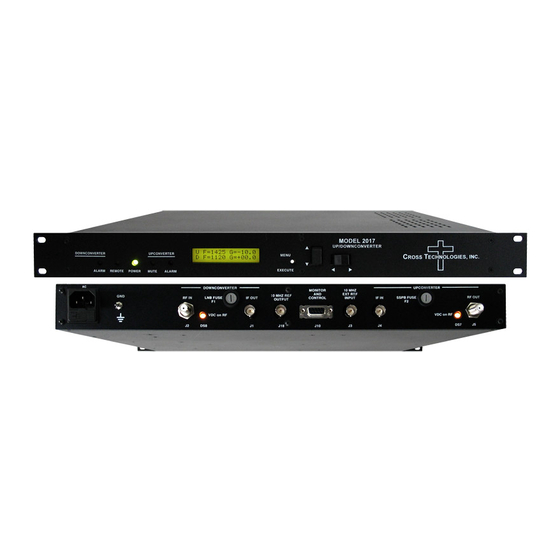
Green LED indicates values in the Menu items when in presence of DC indicates remote program mode. Does not function in power. operation. the normal display mode FIGURE 2.2 3116-7786-2150 Front Panel Controls and Indicators 3116-7786-2150 Manual, Rev. 0 Page 10 11/24/20... - Page 11 2.4 Installation / Operation 2.4.1 Installing and Operating the 3116-7786-2150 Downconverter 1.) Connect a -55 dBm to -35 dBm signal to RF INPUT, J101 (Figure 2.1). 2.) Connect the L-BAND OUTPUT, J1, to the external equipment. 3.) Connect 100-240 ±10% VAC, 47 - 63 Hz to AC connector on the back panel.
-
Page 12: Menu Settings
If programming is initiated and no operator action takes place for approximately 30 seconds (before the final press of the Menu/Execute switch) the display will revert to its previous status and you will need to start over. 3116-7786-2150 Manual, Rev. 0 Page 12 11/24/20... - Page 13 During gain changes, the vertical movement will raise or lower the number in the direction of the arrows. b. For other functions such Remote on/off, the vertical switch will alternately turn the function on or off regardless of the direction operated. 3116-7786-2150 Manual, Rev. 0 Page 13 11/24/20...
- Page 14 OR you can scroll to “R”, push the Menu/Execute switch to get to: SAVE SETTINGS? Selecting Y will save the new settings. Selecting N will revert to the previous settings. Figure 2.4 (page 17) gives the menu items and how to make changes. 3116-7786-2150 Manual, Rev. 0 Page 14 11/24/20...
- Page 15 Selecting Y will save the new settings. Selecting N will revert to the previous settings. Pushing the Menu/Execute switch then takes you to this: FC = 8200.000 G =+ 10.0 REF AUT Figure 2.4 gives the menu items and how to make changes. 3116-7786-2150 Manual, Rev. 0 Page 15 11/24/20...
- Page 16 Internal 10 MHz Reference. REF = AUTO -I appears on the front panel display where -I indicates that the unit is using the Internal 10 MHz Reference. The Internal 10 MHz Reference is present on the reference output connector, J8. 3116-7786-2150 Manual, Rev. 0 Page 16 11/24/20...
- Page 17 Menu 7 Set Remote Interface SCROLL PUSH BUTTON SCROLL <> RS485 ADDRESS = 0 Menu 8 Set RS485 Address SCROLL PUSH BUTTON SAVE SETTINGS? Save? When go to end FIGURE 2.4 Menu Display and Sequences 3116-7786-2150 Manual, Rev. 0 Page 17 11/24/20...
- Page 18 G. Top Cover - There are no serviceable parts inside the product so, the Top Cover should not be removed. If the Top Cover is removed the ground strap and associated screw MUST BE REINSTALLED prior to Top Cover screw replacement. FAILURE TO DO this may cause INGRESS and/or EGRESS emission problems. 3116-7786-2150 Manual, Rev. 0 Page 18 11/24/20...
-
Page 19: Cross Technologies, Inc
ROSS ECHNOLOGIES, INC. 6170 Shiloh Road Alpharetta, Georgia 30005 (770) 886-8005 FAX (770) 886-7964 Toll Free 888-900-5588 WEB www.crosstechnologies.com E-MAIL info@crosstechnologies.com Printed in USA 3116-7786-2150 Manual, Rev. 0 Page 19 11/24/20...
Need help?
Do you have a question about the 3116-7786-2150 and is the answer not in the manual?
Questions and answers