
Related Manuals for Airwell HDD Series


Summary of Contents for Airwell HDD Series
- Page 1 HDD/HED Training Presentation Presented By : Yossi Emquies Jan 12 2011 › ‹ # COMPANY...
-
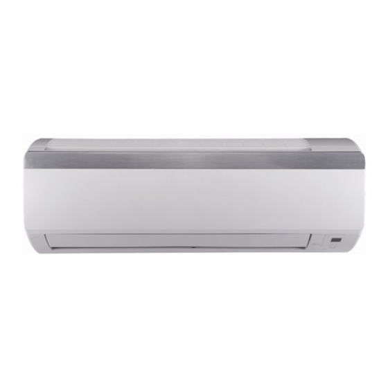
Page 2: Product Description
Product Description The HDD/HED series is a DCI monosplit wall-mounted air conditioner designed mainly for residential applications. The ODU (YDD) is equipped with a DC compressor, using sine wave and torque control technology providing comfort and economical operation. The HDD/HED series includes the following main 4 models capacities : 9 kBtu/h 12kBtu/h 18kBtu/h... - Page 3 Product Range Appearance Airwell- HDD 009/012 Airwell- HDD 018 Airwell- HDD 024 Johnson- DDH 009/012 Johnson- DDH 018 Johnson-DDH 024 Airwell- HED 009/012 Airwell- HED 018 Airwell- HED 024 Electra-JED 009/012 Electra- JED 018 Electra- JED 018 Airwell- YDD 018/024...
- Page 4 Main Key Features DC inverter technology. R410A models. Microprocessor control equipped with indoor 2 segment display . High COP, Energy efficiency class A in cooling/heating mode. Torque control for compressor. Cooling operation at outdoor temperature up to 48ºC. ...
-
Page 5: Specifications
Specifications › ‹ # COMPANY... -
Page 6: Outline Dimensions
Out Line Dimensions (Model 09/12) Indoor Unit Outdoor Unit › ‹ # COMPANY... - Page 7 Out Line Dimensions (Model 18/24) Outdoor Unit Indoor Unit › ‹ # COMPANY...
-
Page 8: Technical Aspects
TECHNICAL ASPECTS › ‹ # COMPANY... -
Page 9: Installation
Installation MAXIMUM PIPES LENGTH & HEIGHT NOM. CAPACITY TUBES O.D. LENGTH HEIGHT PRECHARGE ADDITIONAL CHARGE (kBtu/h) LENGTH 1/4” – 3/8” 15g/m 1/4” – 3/8” 15g/m 1/4” – 1/2” 20g/m 1/4” – 1/2” 20g/m Constrains of installation: Outdoor Unit indoor Unit ›... - Page 10 Intermediate Wiring Connection INDOOR 09/12 INDOOR 18/24 INDOOR OUTDOOR OUTDOOR 09/12/18/24 › ‹ # COMPANY...
- Page 11 IDU Main Display INTRODUCTION OF FUNCTION RUN INDICATOR 1.Lights up when the Air Conditioner is connected to power and the mode is STBY. 2.When the unit is turned on remotely, the RUN LED goes out while the current setting running mode is displayed COOL INDICATOR 1.Lights up during specified operation mode...
- Page 12 RCO8-A Controller Main Functions RC08-A Main Functions - Choose the operating mode (Heating-Dry-Fan or Automatic mode). - Increase or decrease the setting temperature. - Adjust the fan speeds (Auto/Turbo/High/Medium/Low) - Setting ON-OFF timer or present time. - Sleep mode. - Self Clean function. -"I FEEL"...
-
Page 13: Refrigerant Diagram
Refrigerant Diagram (Model 09) › ‹ # COMPANY... - Page 14 Refrigerant Diagram (Model 12) › ‹ # COMPANY...
- Page 15 Refrigerant Diagram (Model 18) › ‹ # COMPANY...
- Page 16 Refrigerant Diagram (Model 24) › ‹ # COMPANY...
- Page 17 Wiring Diagram IDU INDOOR- 09/12 INDOOR- 18/24 › ‹ # COMPANY...
- Page 18 Wiring Diagram ODU OUTDOOR- 09/12 OUTDOOR- 18/24 * EEV is only for Model 24 › ‹ # COMPANY...
- Page 19 IDU PCB Main Inputs and Outputs Layout (Indoor Model 09/12) Indoor controller of model 09/12 * Model 09/12 use similar controller but with different SW. IDU Main Board IDU Display › ‹ # COMPANY...
- Page 20 IDU PCB Main Inputs and Outputs Layout (Indoor Model 09/12) PG motor PG motor Indoor Main Board of model 09/12 power feedback To Display To step motor › ‹ # COMPANY...
- Page 21 IDU PCB Main Inputs and Outputs Layout (Indoor Model 18/24) Indoor controller of model 18/24 IDU Display * Model 18/24 use similar controller but IDU Main Board with different SW and Capacitor › ‹ # COMPANY...
- Page 22 IDU PCB Main Inputs and Outputs Layout (Indoor Model 18/24) Indoor Main Board of model 18/24 To Display ICT,RAT Model Plug PG motor PG Motor Louver motor Feedback Power › ‹ # COMPANY...
- Page 23 ODU PCB Main Inputs and Outputs Layout (Outdoor 09/12) Outdoor controller of model 09/12 PFC Reactor EMI Filter * Model 09/12 use similar controller but with different SW › ‹ # COMPANY...
- Page 24 ODU PCB Main Inputs and Outputs Layout (Outdoor 09/12) ODU Main Board of model 09/12 Fan motor To EMI Filter RV(4-Way valve) AC-IN Sensor set (CTT+OCT+OAT) To DC compressor (U/V/W) › ‹ # COMPANY...
- Page 25 ODU PCB Main Inputs and Outputs Layout (Outdoor 18/24) Outdoor controller of model 18/24 – Flat PCB combines Main Board and EMI Filter together › ‹ # COMPANY...
- Page 26 ODU PCB Main Inputs and Outputs Layout (Outdoor 18/24) Outdoor controller of model 18/24 Sensor set OFAN CTT+OCT+OAT EMI Filter To DC Compressor › ‹ # (U/V/W) COMPANY...
- Page 27 Other issues we need to know Compressor: • Model 09/12 use the same one compressor of Single Rotary type. • Model 18/22 use the same one compressor of Twin Rotary type. Sensors: • CTT: 50K@ 25C • OAT/RAT:15K@25C • OCT/ICT:20K@25C Motors: •...
-
Page 28: Main Control Functions
Main Control Functions › ‹ # COMPANY... - Page 29 Compressor Target Speed Settings PI. Example:Pcoeff=20, Icoeff= 5 PI control Time ∆T Ppart Ipart LOAD Room Set Point Temperature 0+25=25 RoomTemp SetPo 25+15=40 Load Const Const 40+5=45 Proportional Integrative 45+0=45 Part Part 45+0=45 Immediate response for user Takes the effect of the...
- Page 30 Compressor Min and Max Frequencies Frequency Range Maximum Frequency (MaxFreq) Minimum Frequency (MinFreq) Mode See following table Cooling Heating Maximum Frequency Maximum Frequency (MaxFreq) Mode Sleep Mode Cooling Heating Frequency change rate is 1Hz/Sec › ‹ # COMPANY...
-
Page 31: Indoor Fan Control
Indoor Fan Control Auto Fan Mode Under Turbo mode, IFAN will operate at Super High speed. And outdoor will operate at higher compressor frequency. Turbo Function Either pressing TURBO button again or selecting other fan speed can cancel the Turbo Mode. ›... - Page 32 Cooling Mode/ Dry Mode Model 09/12 If RAT≥SPT, the unit starts cooling operation. In this case, the compressor and outdoor fan will operate and the indoor fan will run at the setting speed. If RAT≤SPT-2, the compressor will stop operation and the outdoor fan will delay 30 seconds to stop. While the indoor fan will run at the setting speed.
-
Page 33: Heating Mode
Heating Mode Model 09/12 If RAT<SPT+1.5 AND for certain period, the unit will operate in heating mode. The compressor, outdoor fan and 4-way valve will operate and the indoor fan will delay 3min to start at the latest If RAT≥SPT+1.5, the compressor will stop, the outdoor fan will delay 30s to stop and the indoor fan will blow for 60s at setting speed. - Page 34 Heating Mode Models 9/12 Residual heat blowing function: During heating, when the stopping condition for the compressor is reached, the compressor and the outdoor fan motor stop running while the louver moves to position L. The indoor fan will stop after running for 60s at setting speed.
- Page 35 Auto Mode/ Fan Mode Model 09/12/18/24 In AUTO mode, the system selects the running mode (COOL/HEAT/FAN) automatically according to the room temperature. The display shows the actual running mode and setting temperature. There will be 30s delay for mode conversion. 1.
-
Page 36: Sleep Mode
Sleep Mode › ‹ # COMPANY... - Page 37 Clean Function and I Feel Mode Clean Function I Feel -Function › ‹ # COMPANY...
- Page 38 Protections There are 4 main protection levels: Normal (Norm) – unit operate normally. Stop Rise (SR) – compressor frequency can not be raised but does not have to be decreased. Hz Down – Compressor frequency is reduced by 2Hz/s. Stop Compressor (SC) – Compressor is stopped. Stop Rise and Hz Down are related mainly to the following scenarios : •...
- Page 39 Protections IDU Coil Overheating protection (heating mode): During heating operation, the signals being sent from the indoor unit allows the operation of frequency limitation in order to prevent abnormal high pressure. For Model 09/12: Compressor will stop when ICT reaches 65C For Model 18/22, Compressor will stop when ICT reaches 62C If the unit stops as such protection for 6 times, it can not resume running automatically and displayed an error malfunction, it can...
- Page 40 Protections Compressor Over Current Protection: Model 09/12: Compressor will stop when AC current reaches 14.0A for continuously 2.5s. Model 18/22: Compressor will stop when AC current reaches 17.0A for continuously 2.5s. If the unit stops as such protection for 6 times, it can not resume running automatically and display malfunction, it can resume by pressing ON/OFF.
- Page 41 Protections Deicing Procedure: This protection is for Heat Pump Only This protection is carried out by the cooling cycle (reverse cycle). The defrosting time or outdoor heat exchanger temperature must be more than its setting values when finishing the deicing protection. In the deicing protection, IFAN is forced OFF.
- Page 42 Protections 9/12 Deicing Procedure: 18/24 models: › ‹ # COMPANY...
- Page 43 Protections AC Voltage Drop: During compressor operation, the system will stop in case of an AC voltage malfunction the unit will resume its operation automatically after 3min. Communication malfunction: If the unit does not receive correct signal from indoor unit for 3min continuously, the unit will stop and will show communication malfunction protection;...
- Page 44 Refrigerant Control Concept For Models 09/12/18 capillary method is used. EEV is used only on Model 24: EEV operation after power-on: When power on, EEV will open 240 steps and then move back with 540steps. This position will be recognized as 0. Then EEV will open to 480 steps and be ready for system operating.
- Page 45 Test Mode Procedure Models 9/12: › ‹ # COMPANY...
- Page 46 Test Mode Procedure Models 18/24: › ‹ # COMPANY...
- Page 47 Forced Cooling Mode 18/24 Models Only: › ‹ # COMPANY...
- Page 48 Error Failure Code list and Probable Cause Diagnostic from IDU Display: If the malfunction still exists 4min later after the unit had stopped due to compressor protection, an error code will be directly displayed through the indoor display. In other situations, error code can be displayed by pressing LIGHT button 6 times within 4s.
- Page 49 Error Failure Code list and Probable Cause Sample of 18/24 Sample of 18/24 □ - LED OFF / ■ - LED ON / ☆ - LED BLINK Indoor indicators Outdoor indicators Failure Possible Reasons/Corrective actions 2* 7 LEDs segment (RUN,COOL,HEAT) •Refrigerant was superabundant •Poor heat exchange (including blockage and bad □...
- Page 50 Error Failure Code list and Probable Cause Sample of 18/24 □ - LED OFF / ■ - LED ON / ☆ - LED BLINK Indoor indicators Outdoor indicators Failure Possible Reasons/Corrective actions 2* 7 LEDs segments (RUN,COOL,HEAT) COOL OFF 3S and blink once RAT failure COOL OFF 3S and blink twice ICT failure...
- Page 51 Error Failure Code list and Probable Cause □ - LED OFF / ■ - LED ON / ☆ - LED BLINK Indoor indicators Outdoor indicators Failure Possible Reasons/Corrective actions 2* 7 LEDs segments (RUN,COOL,HEAT) •Abnormal power input voltage. •Compressor wiring mistake. COOL OFF 3S and blink 15 Compressor phase DC over •Liquid and gas valve are not open.
- Page 52 Error Failure Code list and Probable Cause □ - LED OFF / ■ - LED ON / ☆ - LED BLINK Indoor indicators Outdoor indicators Failure Possible Reasons/Corrective actions 2* 7 LEDs segment (RUN,COOL,HEAT) 1.PFC module assembly problem. 2.Poor heat exchange of Heatsink □...
- Page 53 Error Failure Code list and Probable Cause □ - LED OFF / ■ - LED ON / ☆ - LED BLINK Indoor indicators Outdoor indicators Failure Possible Reasons/Corrective actions 2* 7 LEDs segments (RUN,COOL,HEAT) HEAT OFF 3s and blink 18 □...
- Page 54 › ‹ # COMPANY...
Need help?
Do you have a question about the HDD Series and is the answer not in the manual?
Questions and answers