Table of Contents
Advertisement
Quick Links
Advertisement
Table of Contents

Related Manuals for Vestil EPT-S-2748-33


Summary of Contents for Vestil EPT-S-2748-33
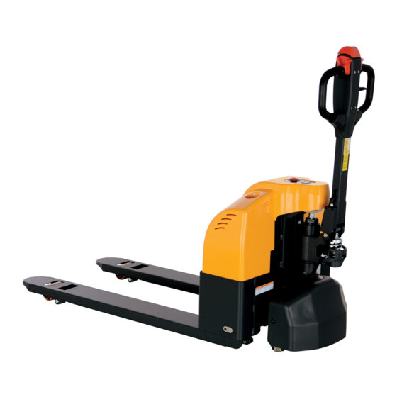
- Page 1 EPT-S-2748-33 SPT15-SMS-001_EN Instruction Manual SPT15 Semi-electric pallet truck EPT-S-2748-33 Operators should read and understand this manual and all warning labels on the Semi-electric pallet truck before using it. Keep the manual for future reference. Release: July. 2010...
- Page 2 EG-Konformitätserklärung EC Declaration of Conformity Hiermit erklären wir, NOBLELIFT EQUIPMENT Jingyi Road, Changxing, Zhejiang, China We herewith declare Daß die nachfolgend bezeichnete Maschine aufgrund ihrer Konzipierung und Bauart sowie in der von uns in Verkehr gebrachten Ausführung den einschlägigen grundlegenden Sicherheits- Gesundheitsanforderungen EG-Richtlinien...
- Page 3 Preface Welcome to use this series of Semi-electric pallet trucks SPT15. In order to ensure your safety and to correctly operate the shop crane, please thoroughly read and understand all instructions in the Instruction Manual as well as all label instructions before operating it for the first time. Please keep the Instruction Manual handy for reference whenever necessary.
-
Page 4: Guidelines For Safe Operation
Guidelines for Safe Operation Requirements for the operator The pallet truck should only be operated by trained personnel. The right, duty and responsibility of the operator Clear with his own right and duty, the operator should be trained in operating the pallet truck and also knows the contents in this operation manual very well. - Page 5 High-risk environment Trucks that will be operated in high-risk environment must be equipped with special safety devices. If operated in fuel depots, the truck must be equipped with antistatic devices. The truck is not designed for use in high-risk environment Driving in public places: The truck is prohibited to drive in public places except for special areas.
- Page 6 1.12 Passing a ramp Only known ramps are permitted to pass. The ramps must also be clean, anti-skid and meet specification requirements of the truck. Loads on the fork must face the downward slope. Never turn around, drive obliquely or stop on a slope. Slow down when passing a ramp. 1.13 Safe Parking Pay attention to safety when parking the truck.
- Page 7 Outline drawing and technical parameters 2.1.2 SPT15 Model SPT15 EPT-S-2748-33 Rated loading capacity 1500 3,000 Load centre distance inch 23-5/8 Front overhang distance 1008 inch 39-11/16 Track 1275 1345 inch Weight (with accumulator) Wheels (rubber, high-performance Polyurethane elastomer, pneumatic tyre, polyurethane) Dimension of driving wheel Φ220×70...
- Page 8 Electromagnetic Compatibility (EMC) The manufacturer confirms that the truck complies with EN12895 and other relevant standards on limits of electromagnet radiation and interference, and has been tested on static discharge. Never modify any part of electrical system without written permission from the manufacturer. 2.3 Operation Conditions Ambient temperature: 5℃~40℃...
- Page 9 3 Transport and Trial Run 3.1 Loading and Unloading This truck acquires wooden block packaging; so it can be loaded or unloaded with a forklift and a crane. 3.2. Installation of Handle You may need some tools for installation, such as a hammer and a pair of pliers, etc.; you also need some accessories: a perforated shaft, two spring pins (note: one has been installed on the shaft).
- Page 10 Squat behind the truck when installing the handle and follow the steps below: 3.2.1 Place the handle on the small piston, and then use a hammer to knock the perforated pin into the hydraulic pump and handle from right to left. 3.2.2 Shift the finger lever to the "Lowering"...
- Page 11 finger lever is being pressed. 3.3.2 If the fork lowers when depressing the finger lever at the middle, turn the adjusting screw or the adjusting nut counter clockwise until the fork does not lower when the finger lever is being pressed.
-
Page 12: Operational Manual
4 Operational Manual 4.1 Lever Operation 4.1.1 Finger Lever: Three Positions “Lifting, Neutral and Lowering” (see section 3.3) can be used to raise and lower the fork. 4.1.2 Drive switch: controls the speed and direction (forward and backward) of vehicle traveling. 4.1.3 Horn button: 4.1.4 Approach switch: Press the approach switch, the truck will stop immediately and drive a little towards the opposite direction. - Page 13 Check the horn; Check the brake function of the lever. Now, prepare work before start-up is completed. 4.3 Operation 4.3.1 Start-up, Drive, Stop Before starting-up and driving the truck, you should warn other people, especially when they are in contact with the truck. The operator must note that it is prohibited to transport or lift personnel with the truck.
- Page 14 methods are available: Electromagnetic brake (finger lever) Reverse current brake (from the controller) Inertia brake (Release the brake) Electromagnetic brake In case of emergency, the truck can be only stopped with electromagnetic brake (press button switch, or leave the finger lever as vertical or press it as horizontal). ...
- Page 15 Lifting of the fork The finger lever (217) is at the “Lifting” position. With an up/down motion of the handle, the fork can be raised. The finger lever (217) is at the “Lowering” position, the fork can be lowered.
- Page 16 Maintenance, Recharging and Replacement of the Accumulator 5.1 Safety procedures for accumulator operation The truck must be parked in a safe location before any operation on the accumulator. 5.1.1 Maintenance Technician Only a qualified technician can perform operations on the accumulator such as recharging, maintenance and replacing.
- Page 17 5.2 Specification of the accumulator Weight and dimensions can be found on the label of the accumulator. Uninsulated terminal poles on the accumulator should be protected with an insulated cover. 5.3 Capacity indicator of the accumulator Capacity indicator of the accumulator: The status of accumulator discharging is indicated on the indicator with 10 bar graphs, each bar represents 10 percent of increment.
- Page 18 6 Maintenance and Service Manual The Semi-electric pallet truck needs frequent daily inspection and maintenance. 6.1 Daily Inspection & Maintenance ① Hydraulic oil: Check the hydraulic oil every 6 months. The capacity is 0.3 Liter. Please select the suitable hydraulic oil according to the table below. Temperature Hydraulic Oil L-HV46 hydraulic oil...
- Page 19 Lubrication Cycle Table ◆= Refill opening Refill point Lubrication Cycle 500 h 1000 h 2000h Bearings loading wheels Shaft sleeve Bearings supporting wheels Gear box Steering bearing Joints L=Lubricating C=Checking Description tables of oil and lubricant Lubricant type Lubricant Name Lubricated area >-15℃...
-
Page 20: Troubleshooting
6.2. Troubleshooting This chapter provides a guide to users on finding out and solving simple faults of the pallet truck. The following table introduces faults determination and solving methods. Faults Cause Countermeasures The fork frame - Low hydraulic oil level - Add hydraulic oil can’t reach the maximum... - Page 21 - The proximity switch is damaged - Replace the proximity switch Emergency - The wires are aged or damaged - replace the wires changeover - The connector gets loose or falls - Check the connectors and secure fails them - The Emergency stop switch is - Replace the emergency stop Emergency damaged...
-
Page 22: Wiring/ Circuit Diagram
9. WIRING/ CIRCUIT DIAGRAM Electrical circuit diagram Fuses EPT-S-2748-33 10A FU01 : Fig. 22: Electric diagram EPT-S-2748-33... -
Page 23: Schematic Diagram
7 Schematic Diagram 7.1 Circuit diagram The following are names of electric components: Proximity switch Code Name Accumulator S1、S2 Micro-switch FU0、FU Fuse Key switch Main contactor Accelerator Temperature protective Charger module Button switch Electromagnetic brake Controller Coulombmeter Traction motor Diode Horn Spring...
Need help?
Do you have a question about the EPT-S-2748-33 and is the answer not in the manual?
Questions and answers