
Related Manuals for Vestil S SERIES


Summary of Contents for Vestil S SERIES
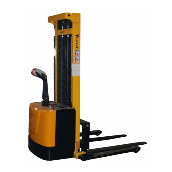
- Page 1 OPERATION & SERVICE MANUAL S SERIES STACKER WITH POWER DRIVE & POWER LIFT Vestil Manufacturing Corp. 2999 North Wayne St., Angola, IN 46703 Ph: 260-665-7586 Fax: 260-665-1339 E-mail: Sales@vestil.com Website: www.vestil.com...
-
Page 2: Table Of Contents
General ………………………………………………………………………………………………... Specification ………………………………………………………………………………………… Receiving instructions …………………………………………………………………………... ……….………………………………………………………………………………… 6 Safety Notes Product description ………………………………………………………………………………. Designated use …. … …... … ………………………………………………………………….. Signs on the Stacker …………………………………………………………………………… Removing From the Pallet ……………………………………………………………………. 9 Operation ……………………………………………………………………………………………... 10 Operation ……………………………………………………………………………………………... Operating elements ……………………………………………………………………………… Safety elements ………………………………………………………………………………….. -
Page 3: General
Introduction Read and follow the instructions contained in this operating manual. Only trained, well-informed personnel, who have been instructed in accordance with this operation manual, may use or work on the stacker. Liability or guarantee is waived if: The instructions in this operating manual are not observed. The high-lift stacking truck is operated, cleaned or maintained incorrectly. -
Page 4: Specification
Stacker, Motorized, Electric, Cap 2000 Lbs Powered drive / powered lift pallet stacker truck. Raise, lower and maneuver loads quickly and easily. An easy-to-operate thumb-wheel allows infinite forward and reverse travel speeds of 3.8 mph unloaded / 3.1 mph loaded. Fingertip raise and lower buttons, horn and a safety-reverse control-button are conveniently located. An electromagnetic disc brake with automatic dead-man feature activates when the user releases the handle. -
Page 5: Receiving Instructions
Receiving Instructions Every unit is thoroughly tested and inspected prior to shipment. However, it is possible that the unit may incur damage during transit. If you see damage when unloading, make a note of it on the SHIPPER RECEIVER. Remove all packing & strapping material, inspect for damage. IF DAMGE IS EVIDENT, FILE A CLAIM WITH THE CARRIER IMMEDIATELY! Also, check fork size, type of power unit, etc., to see that the unit is correct for the intended application. -
Page 6: Safety Notes
Safety notes Symbols and pictures In addition to the text and illustrations, this operating manual contains various symbols which should draw attention to the safety requirements. They generally have the following appearance: Signal wording Explanation DANGER Warning of an imminent danger! Non-observance cause death or serious injury Warning of a possibly incoming dangerous situation. -
Page 7: Product Description
Product description Designated use The stacker is designated for lifting, lowering and transportation of loads according to the specifications of the identification plate. The stacker is to be used on hard level surfaces. To move the stacker between buildings, warehouses etc The gradient of the slope must not be more than 10% Make sure load is not loose or unstable. -
Page 8: Signs On The Stacker
Product description... -
Page 9: Removing From The Pallet
Removing from the pallet CAREFUL To pick up the unit only use overhead hoist, or forklift with sufficient carrying capacity & take into consideration the center of gravity of the unit. Use top crossmember to lift the equipment. Be careful of the stacker swinging once fully lifted off the pallet or skid. Remove the pallet or skid from below the lift &... -
Page 10: Operation
OPERATION Visually inspect stacker for damaged and worn parts, before stacker is taken into operation. Authorized person should read and understand all instructions The lifting truck is ready for immediate use once the packaging has been removed. The battery is full and charged. The hydraulic tank is full. -
Page 11: Operation
Operation... -
Page 12: Safety Elements
Operation... -
Page 13: Driving, Braking And Horn
Operation Driving Pull up the red push button of the E-switch Tilt the Control handle to driving position, the locking brake is released If you release Control handle, this returns to the vertical start position, the truck brakes and the locking brake activates The truck is steered via the Control handle Brake: This stacker is equipped with a magnetic brake that is applied between... -
Page 14: Lifting And Lowering
To raise and lower The following are generally valid for the lifting and lowering procedure: The red operating button of the EMERGENCY STOP pushbutton must be pulled upwards Lifting and lowering movements are initiated by pressing the pushbuttons on the handle head. There are four buttons located on the two sides of the handle. -
Page 15: Traveling
Travel The butterfly switch controls the direction and speed of the lift truck. Rotating the butterfly control towards the forks moves the truck in the forward direction. Rotating the butterfly control away from the forks, moves the truck in the reverse direction. The control is progressive – the further you rotate the control, the faster the truck will travel. -
Page 16: Lifting The Load
Operation Lifting load CAUTION! Before lifting a load to be transported, ensure that the load does not exceed the carrying capacity of the truck. The nominal carrying capacity and lifting heights can be viewed in the load diagram. Ensure that the load can be lifted up in a compact and stable manner. Slipping or falling of the load must be avoided. -
Page 17: Maintenance And Repair
Maintenance and repair -- ______ ROUBLESHOOTING UIDE Warning: Before performing any task, always block drive wheel off of the ground. Consult the factory for problems at time of installation, or for any problems not addressed below. Problem: Possible cause(s): Action: Unit doesn’t move when controls are Battery voltage low (<17) Charge batteries. - Page 18 Problem: Possible cause(s): Action: Unit will not go forward, or reverse, Broken wire, or loose connection, Locate Pin 6 on Molex connector at but belly switch still functions bad motor controller, the motor controller. Try to drive properly. the unit in forward, there should be 0 to 5 volts (5 v is full throttle) at this pin.
- Page 19 Problem: Possible cause(s): Action: Unit will not reverse; belly switch Broken wire, or loose connection, Locate Pin 12 on Molex connector at does not function; forward ok bad motor controller the motor controller. Try to drive the unit in reverse; there should be 24 volts at this pin.
- Page 20 Problem: Possible cause(s): Action: Unit will not raise; motor does not Loose wire Verify 24 volts at coil when raise is pushed, if no voltage; trace wiring back to till her head looking for voltage on each side of the connectors until the bad Bad solenoid connection is found.
- Page 21 Problem: Possible cause(s): Action: Unit will not reverse; belly switch Broken wire, or loose connection, Locate Pin 12 on Molex connector at does not function; forward ok bad throttle assembly, bad motor the motor controller. Try to drive controller. the unit in reverse; there should be 24 volts at this pin.
-
Page 22: Changing Batteries
Filename: Changing Batteries in S-62 Stacker VESTIL MFG. CO. Model: S-62/AA/FF/FA Instructions for Changing the Batteries, estimated time, 15 min. READ ALL INSTRUCTIONS BEFORE PROCEEDING! Only qualified personnel should work on this equipment! Lock out all potential energy sources before attempting this installation; turn off the unit and remove the key. -
Page 23: Troubleshooting
Troubleshooting: If the unit does not operate, check all of the wiring connections to make sure they’re both mechanically and electrically sound – specifically at the battery, and the motor. A fully-charged lead acid battery in good condition at room temperature should read 12.65 volts. At 11.9 volts it is considered to be fully discharged and in need of charging. -
Page 24: Changing Motor Controller
Filename: Changing Motor Controller in S-62 Stacker VESTIL MFG. CO. ModelS-62-AA/FF/FA Instructions; Changing the Motor Controller in; estimated time, 30 min. READ ALL INSTRUCTIONS BEFORE PROCEEDING! Only qualified personnel should work on this equipment! Lock out all potential energy sources before attempting this installation; turn off the unit and remove the key. - Page 25 Filename: Changing Motor Controller in S-62 Stacker VESTIL MFG. CO. ModelS-62-AA/FF/FA Verify power if off to the unit; key switch off! Remove yellow cover; two screws on top. The Campro motor controller is shown here.
- Page 26 Filename: Changing Motor Controller in S-62 Stacker VESTIL MFG. CO. ModelS-62-AA/FF/FA The wiring must be marked The wiring should be marked in a unique way to remember where it all goes when re-connecting. One possible method is shown below. Remove the two 14mm bolts holding the motor controller mounting plate to the frame.
- Page 27 Filename: Changing Motor Controller in S-62 Stacker VESTIL MFG. CO. ModelS-62-AA/FF/FA Two bolts, one front and one back. Remove the Molex connector from the motor controller.
- Page 28 Filename: Changing Motor Controller in S-62 Stacker VESTIL MFG. CO. ModelS-62-AA/FF/FA Remove the motor controller wiring with two 14mm wrenches.
- Page 29 Filename: Changing Motor Controller in S-62 Stacker VESTIL MFG. CO. ModelS-62-AA/FF/FA Wiring shown here removed. Remove 3x 8mm screws holding the motor controller to the back plate with a Philips screwdriver, and 8mm wrench. 1 screw in back and two in the front.
-
Page 30: Changing Motor Controller
Filename: Changing Motor Controller in S-62 Stacker VESTIL MFG. CO. ModelS-62-AA/FF/FA Remove the motor controller, and replace with a new controller by reversing the above steps. Verify the 4 spade terminal connections are still good on the forward / reverse motor contactor. The contactor is just... -
Page 31: Belly Switch Trouble Shoot
Filename: Belly Switch trouble shoot VESTIL MFG. CO. Model: S-62-AA/FF/FA Instructions for Changing the Tiller Assembly; S-62-AA/FF/FA estimated time, 30 min. READ ALL INSTRUCTIONS BEFORE PROCEEDING! Only qualified personnel should work on this equipment! Lock out all potential energy sources before attempting this installation; turn off the unit and remove the key. - Page 32 Filename: Belly Switch trouble shoot VESTIL MFG. CO. Model: S-62-AA/FF/FA Troubleshooting: If the unit does not operate, check all of the wiring connections to make sure they’re both mechanically and electrically sound – specifically at the battery, and the motor.
- Page 33 Filename: Belly Switch trouble shoot VESTIL MFG. CO. Model: S-62-AA/FF/FA S-62-XX; verify this is the unit you are working on. Make sure E-switch is off (pushed down). Fig.2...
- Page 34 Filename: Belly Switch trouble shoot VESTIL MFG. CO. Model: S-62-AA/FF/FA This is the top side of the tiller. Fig3 Fig.3 This is the driver side of the tiller, looking at the belly switch. Fig 4 Fig.4...
- Page 35 Filename: Belly Switch trouble shoot VESTIL MFG. CO. Model: S-62-AA/FF/FA This is the bottom side of the tiller handle. 3 allen head screws need to be removed. Fig5 Fig.5 Lift the front top edge of the tiller cover up. Fig6...
- Page 36 Filename: Belly Switch trouble shoot VESTIL MFG. CO. Model: S-62-AA/FF/FA Carefully pull the belly switch back off of the tiller while tipping the front up. Fig 8 Fig.8...
- Page 37 Filename: Belly Switch trouble shoot VESTIL MFG. CO. Model: S-62-AA/FF/FA The tiller assembly cover should come off, just be careful not to drop it and rip out the wiring from the connectors. At this point, the tiller throttle assembly can be replaced with a new one by just unplugging the two connectors.
- Page 38 Filename: Belly Switch trouble shoot VESTIL MFG. CO. Model: S-62-AA/FF/FA Remove Philips screw on throttle. Fig11 Fig.11 Throttle wheel will then pull off. Take note of the orientation of the wheel on the shaft. Correct orientation is shown here. Fig 12...
- Page 39 Model: S-62-AA/FF/FA Do the same on the other side, taking note of the orientation of the two plastic bushings. If the throttle wheel had a tendency to stick, contact Vestil Manufacturing for replacement bushings. Fig 13 Fig.13 The front of the red cover should be connected via the gray nub. Fig 14...
- Page 40 Filename: Belly Switch trouble shoot VESTIL MFG. CO. Model: S-62-AA/FF/FA To remove the red cover, use a small screwdriver and carefully lift the plastic up over the gray nub. Fig 15 Fig.15 Do the same on the other side, and remove. Fig 16...
- Page 41 Filename: Belly Switch trouble shoot VESTIL MFG. CO. Model: S-62-AA/FF/FA This should expose a spring. This spring has a specific orientation. When assembled the spring sets in the red cup on the inside of the red belly cover. Fig 17 Fig.17...
- Page 42 Also verify the belly switch is not stuck in. You should be able to push on the switch and the actuator will move freely in and out, you should here a click as you do this. If the switch is stuck in contact Vestil Manufacturing for replacement options. Fig19...
- Page 43 Filename: Belly Switch trouble shoot VESTIL MFG. CO. Model: S-62-AA/FF/FA The spring can be pushed into position. Fig. 21 Fig.21 This is the spring shown not seated completely. Push the spring into the pocket, and over the gray plastic nub. Fig22...
- Page 44 Filename: Belly Switch trouble shoot VESTIL MFG. CO. Model: S-62-AA/FF/FA Install bushings. Fig23 Fig.23 Put throttle thumb wheels back on. Fig24 Fig.24...
- Page 45 Filename: Belly Switch trouble shoot VESTIL MFG. CO. Model: S-62-AA/FF/FA Install Philips screw. Fig25 Fig.25 Re-installing the tiller cover is basically reversing steps Fig 5 thru 9; with the following precautions/steps. Make sure red tabs on each side goes on top of black nubs when installing tiller cover on the handle. Fig 26...
- Page 46 Filename: Belly Switch trouble shoot VESTIL MFG. CO. Model: S-62-AA/FF/FA Black nub for right side shown here; and the next photo Fig 27 Fig.27 The red tab slides over the top of this black nub on each side when installing the tiller throttle assembly back on the handle.
- Page 47 Filename: Belly Switch trouble shoot VESTIL MFG. CO. Model: S-62-AA/FF/FA This shows sliding the red tabs over the black nub. This is basically the reverse of Fig8. Fig28 Red tab Black nub This is the top front where the two connectors are. Make sure they are on each side of the stand off so the wires do not get pinched.
- Page 48 Filename: Belly Switch trouble shoot VESTIL MFG. CO. Model: S-62-AA/FF/FA Gently push the tiller throttle assembly in place. Again, it’s just reversing steps 5 through 9 to get the tiller throttle assembly back on the handle. Re-install the 3 allen screws, verify no switches are sticking, and that the thumb wheel moves freely.
-
Page 49: Maintenance Daily/Before Use, Monthly, Annually
Maintenance and repair (A) BEFORE EACH USE INSPECT FOR THE FOLLOWING: 1) Frayed wires 2) Oil leaks 3) Pinched or chafed hoses 4) Damage or structural deformation to the structural members, the cylinder brackets, etc. 5) Unusual noise or binding, or evidence thereof. 6) Proper functioning of all limit switches, including those on the perimeter pinch point guard (if applicable) 7) Horn works 8) Load chain, check for mechanical damage, check for play (slack chain) -
Page 50: Maintenance And Care Of The Load Chains
Maintenance and repair Maintenance and care of the load chains In normal use the load chains should be re-lubricated every 250 operating hours; in the event of heavy soiling, moisture and very high prolonged loading, re-lubrication should be effected after 100 operating hours. If subject to corrosive media the chain should be cleaned and lubricated immediately. -
Page 51: Chain Inspections
Maintenance and repair Chain inspections Chains used in stackers should be inspected at least once a year or every three months if exposed to severe contamination or high continuous loading stress. We recommend that attention be paid to the following points: 1. -
Page 52: Temporary Lay-Up
Maintenance and repair Temporary lay-up If, for operating reasons, the stacker is laid up for more than two months, the following instructions are to be carried out: Place the stacker on blocks so that all the wheels are raised from the floor. In this way, they will be prevented from becoming permanently misshapen. -
Page 53: Warranty
Angola, Indiana. Who may request service? Only the warrantee may request service. You are a warrantee if you purchased the product from Vestil or from an authorized distributor AND Vestil has been fully paid. What is covered under the warranty? The warranty covers the following original drive and lift components: drive motors and lift motors, hydraulic pumps, electronic controllers, switches and cylinders. -
Page 54: Parts List
Part list Electric wiring... - Page 55 Part list Electric circuit...
- Page 56 Part list S-62 Electric component list Name Code Specification Battery 12V/70Ah 2PCS Controller 1207A-4102 Drive motor DC24V/0.7KW Lift motor DC24V/2.0KW Lift motor contactor MZJ200S 24V Drive motor contactor MZJ200S 24V Direction contactor J3.1 DC88-1 24V Direction contactor J3.2 DC88-1 24V Control circuit fuse Ø6X30 10A Hydraulic circuit fuse...
- Page 57 HYDRAULIC CIRCUIT DIAGRAM...
- Page 58 Part list...
- Page 59 Part list...
-
Page 60: Parts List
Part list...
Need help?
Do you have a question about the S SERIES and is the answer not in the manual?
Questions and answers