Advertisement
Quick Links
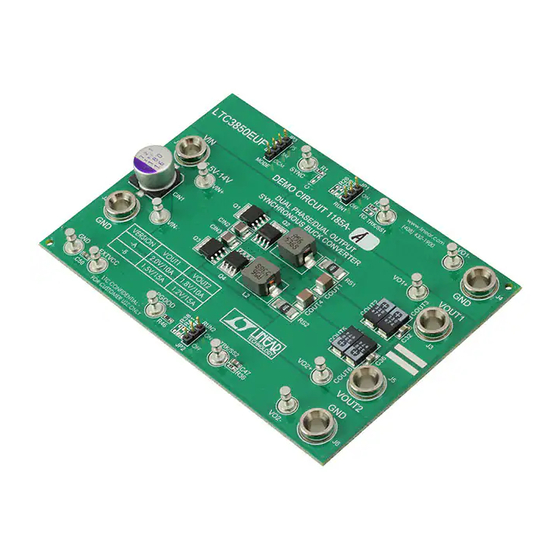
DESCRIPTION
Demonstration circuit 1185 is a dual phase/dual output
synchronous buck converter featuring the LTC3850EUF.
The demo board comes in two versions. The output volt-
ages for version DC1185B-A are 2.0V/10A and 1.8V/10A.
The output voltages for version DC1185B-B are 1.5V/15A
and 1.2V/15A. The input voltage range is 6.5V to 14V for
both versions. For applications that have a 5V ±0.5V input,
the board has an optional resistor to tie the INTVCC pin
to the VIN pin.
The demo board uses a high density, 2-sided drop-in layout.
The power components excluding the bulk output and input
capacitors, fit within a 1.35" × 0.75" area on the top layer.
The control circuit resides in a 0.60" × 0.75" area on the
bottom layer. The package style for the LTC3850EUF is a
4mm × 4mm 28-lead QFN with an exposed ground pad.
PERFORMANCE SUMMARY
PARAMETER
Minimum Input Voltage
Maximum Input Voltage
Version DC1185B-A
Output Voltage V
OUT1
Output Voltage V
OUT2
Nominal Switching Frequency
Full-Load Efficiency
(See Figure 3 for Efficiency Curves)
Version DC1185B-B
Output Voltage V
OUT1
Output Voltage V
OUT2
Nominal Switching Frequency
Full-Load Efficiency
(See Figure 4 for Efficiency Curves)
Synchronous Buck Converter
The main features of the board include an internal 5V linear
regulator for bias, RUN pins for each output, an EXTVCC
pin and a PGOOD signal. The board can be configured
for either CCM (original setting), Burst Mode
skipping operation with the MODE jumper. The board
also has optional resistors for single output/dual phase
operation, rail tracking, DCR sensing and synchronization
to an external clock.
Design files for this circuit board are available at
http://www.linear.com/demo
L, LT, LTC, LTM, Linear Technology, the Linear logo and Burst Mode are registered trademarks
of Linear Technology Corporation. All other trademarks are the property of their respective
owners.
Note: Q1-Q4 MOSFETs changed on September 10, 2013.
See Schematic Diagram.
Specifications are at T
CONDITION
I
= 0A to 10A
OUT1
I
= 0A to 10A
OUT2
V
= 2.0V, I
= 10A, V
= 12V
OUT1
OUT1
IN
V
= 1.8V, I
= 10A, V
= 12V
OUT2
OUT2
IN
I
= 0A to 15A
OUT1
I
= 0A to 15A
OUT2
V
= 1.5V, I
= 15A, V
= 12V
OUT1
OUT1
IN
V
= 1.2V, I
= 15A, V
= 12V
OUT2
OUT2
IN
DEMO MANUAL
DC1185B-A/-B
Dual Phase/Dual Output
= 25°C
A
VALUE
6.5V
14V
2.0V ±2%
1.8V ±2%
500kHz
90.2%
89.5%
1.5V ±2%
1.2V ±2%
400kHz
88.1%
86.5%
LTC3850EUF
, or pulse-
®
dc1185b-a/-bf
1
Advertisement

Related Manuals for Linear Technology DC1185B-A


Summary of Contents for Linear Technology DC1185B-A
- Page 1 The power components excluding the bulk output and input L, LT, LTC, LTM, Linear Technology, the Linear logo and Burst Mode are registered trademarks capacitors, fit within a 1.35" × 0.75" area on the top layer. of Linear Technology Corporation. All other trademarks are the property of their respective owners.
-
Page 2: Quick Start Procedure
DEMO MANUAL DC1185B-A/-B QUICK START PROCEDURE Demonstration circuit 1185 is easy to set up to evaluate Note: Make sure that the input voltage does not exceed 15V. the performance of the LTC3850EUF. Refer to Figure 1 Check for the proper output voltages. - Page 3 SENSE SENSE LOAD CURRENT (A) LOAD CURRENT (A) Figure 3. Efficiency Curves for the DC1185B-A Figure 4. Efficiency Curves for the DC1185B-B SINGLE OUTPUT/DUAL PHASE OPERATION A single output/dual phase converter may be preferred 2. Tie ITH1 to ITH2 by stuffing 0Ω at R49.
- Page 4 DEMO MANUAL DC1185B-A/-B RAIL TRACKING Demonstration circuit 1185 is set up for independent This board can be modified on the bench to allow VOUT1 turn-on of VOUT1 and VOUT2. The ramp-rate for VOUT1 is to track an external signal. It can also be modified to...
- Page 5 DEMO MANUAL DC1185B-A/-B INDUCTOR DCR SENSING Demonstration circuit 1185 provides an optional circuit = 2.0V/10A OUT1 for DCR sensing. DCR sensing uses the DCR of the in- = 1.8V/10A OUT2 ductor to sense the inductor current instead of discrete = 6.5V to 14V sense resistors.
- Page 6 DEMO MANUAL DC1185B-A/-B SYNCHRONIZATION TO AN EXTERNAL CLOCK The LTC3850 uses a phase-lock-loop which forces its 1. Remove R7. internal clock to be synchronized to an external clock. 2. Stuff 10kΩ at R8. Once synchronized, the rising edge of the top FET gate is 3.
-
Page 7: Parts List
DEMO MANUAL DC1185B-A/-B PARTS LIST (DC1185B-A) ITEM REFERENCE PART DESCRIPTION MANUFACTURER/PART NUMBER Required Circuit Components C11, C32, C36 CAP, 0805 4.7µF 10% 6.3V X5R AVX 08056D475KAT C12, C14, C15, C41, C44 CAP, 0603 1nF 10% 50V X7R AVX 06035C102KAT C2, C17, C20, C21, C47 CAP, 0603 0.1µF 10% 25V X7R... - Page 8 DEMO MANUAL DC1185B-A/-B PARTS LIST (DC1185B-B) ITEM REFERENCE PART DESCRIPTION MANUFACTURER/PART NUMBER Required Circuit Components C11, C32, C36 CAP, 0805 4.7µF 10% 6.3V X5R AVX 08056D475KAT C12, C14, C15, C41, C44 CAP, 0603 1nF 10% 50V X7R AVX 06035C102KAT C2, C17, C20, C21, C47 CAP, 0603 0.1µF 10% 25V X7R...
-
Page 9: Schematic Diagram
Information furnished by Linear Technology Corporation is believed to be accurate and reliable. However, no responsibility is assumed for its use. Linear Technology Corporation makes no representa- tion that the interconnection of its circuits as described herein will not infringe on existing patent rights. - Page 10 Linear Technology Corporation (LTC) provides the enclosed product(s) under the following AS IS conditions: This demonstration board (DEMO BOARD) kit being sold or provided by Linear Technology is intended for use for ENGINEERING DEVELOPMENT OR EVALUATION PURPOSES ONLY and is not provided by LTC for commercial use. As such, the DEMO BOARD herein may not be complete in terms of required design-, marketing-, and/or manufacturing-related protective considerations, including but not limited to product safety measures typically found in finished commercial goods.
- Page 11 Mouser Electronics Authorized Distributor Click to View Pricing, Inventory, Delivery & Lifecycle Information: Analog Devices Inc. DC1185B-A DC1185B-B...
Need help?
Do you have a question about the DC1185B-A and is the answer not in the manual?
Questions and answers