
Related Manuals for ALLNIC AUDIO A-2500


Summary of Contents for ALLNIC AUDIO A-2500
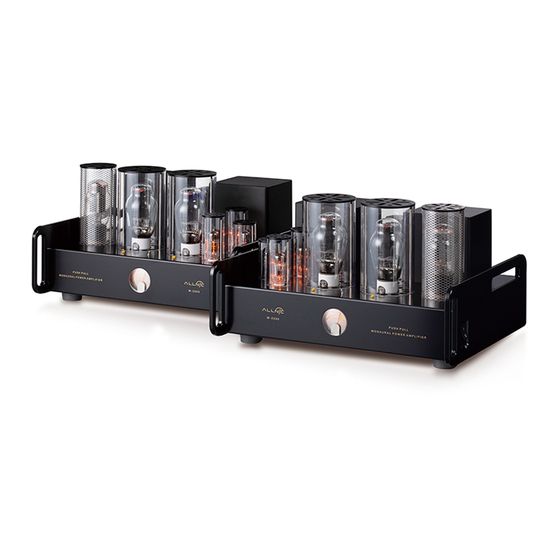
- Page 1 ALLNIC AUDIO A-2500 211/845 SINGLE-ENDED TRIODE MONOBLOCK POWER AMPLIFIERS OWNER’S MANUAL...
- Page 2 211/845 SINGLE-ENDED TRIODE (SET) MONOBLOCK POWER AMPLIFIERS Thank you for purchasing the Allnic Audio A-2500 SET Monoblock Power Amplifiers. We are certain your trust in Allnic Audio and its dealers worldwide, as well as your appreciation for the sound of this high-quality device, will be rewarded by its excellent operation for years to come.
-
Page 3: Table Of Contents
TABLE OF CONTENTS: INTRODUCING THE A-2500 211/845 SINGLE-ENDED TRIODE MONOBLOCK POWER AMPLIFIERS WHAT’S IN THE BOX? SAFETY CLEANING Chassis Connectors INITIAL SET-UP Location, Location, Location Inputs Speaker Terminals Power Connection INITIAL POWER ON OPERATION TUBES AND TUBE BIAS SPECIFICATIONS WARRANTY... -
Page 4: Introducing The A-2500 211/845 Single-Ended Triode Monoblock Power Amplifiers
The A-2500 is Allnic Audio’s most powerful, power tube flexible, single-ended monoblock power amplifier model. Like all Allnic Audio products, the A-2500s have Permalloy (iron and nickel alloy) for their transformer cores. Allnic is grateful to Mr. G.W. Elmen of Western Electric for inventing Permalloy for transformer core use, and in so doing, providing an enormous service to recorded music listeners everywhere. -
Page 5: What's In The Box
The meter offers a simple, unambiguous indication of the tube's status compared to conventional LED bias monitors. • As are all Allnic Audio products, the A-2500s are fully RoHS (EU Reduction of Hazardous Substances regulation) compliant in construction and materials. -
Page 6: Cleaning
INITIAL SET-UP LOCATION, LOCATION, LOCATION Like all audio products using tubes, the Allnic Audio A-2500s need to be placed on a solid stand in a location that provides good air circulation around, above and below the monoblocks. • DO NOT cover the tops of the A-2500s. -
Page 7: Inputs
(facing the back) rear of the chassis, with the balanced input closest to the side edge. The inputs are on the left rear of the chassis on the other A-2500. Between the inputs, there is a switch to select one of two pin configurations for a balanced cable (i.e., it changes the phase). -
Page 8: Operation
In the case of any failure, please contact Your Allnic dealer for assistance. THE CURRENT METER The illuminated meter indicates the current supply to the 211/845 power tube in the A-2500. There is a screw-type potentiometer control on the chassis top in front of each 211/845. - Page 9 If the meter’s needle drops to the left limit of the meter’s face during operation, this indicates a failure of the related 211/845 tube. You must turn off the A-2500 and replace the 211/845 and, probably, the protection fuse (0.5A, 250V, 20mm slow-blow) for the tube. To replace the fuse, using a screwdriver, simply turn the top of the fuse cap (located just behind the 211/845 tube –...
-
Page 10: Specifications
WARRANTY FOR WARRANTY SERVICE, PLEASE CONTACT YOUR AUTHORIZED ALLNIC DEALER. All Allnic Audio amplifier products are warranted against materials and manufacturing defects for parts, excluding tubes, and labour for two (2) years from date of purchase. Tubes are warranted against... -
Page 11: Figures
Date of purchase is the date indicated on the invoice for the product issued by Allnic Audio or its authorized representative. For the warranty to be valid, a defective product must be returned to Allnic Audio’s authorized representative for service prior to any unauthorized attempt to repair. - Page 12 Figure 2: A-2500 – Rear View...
- Page 13 Figure 3: A-2500 – Front View...
- Page 14 Figure 4: A-2500 – Top View...
Need help?
Do you have a question about the A-2500 and is the answer not in the manual?
Questions and answers